Precision RL1848TB User manual

Owner’s Manual | RL1848TB
Lawn Roller
Caution: Carefully read all rules and instruction for safe operation.
Manual Contents Your New Lawn Roller
Congratulations on your purchase of a new
Precision Products Inc. Lawn Roller. Your Roller has
been engineered and built to give you the most
dependable and best performing product possible.
If you experience any problem you can not easily
resolve, please feel free to contact our
knowledgeable and helpful customer service
department toll-free at 1 (800) 225-5891.
Form No. 2017 (04/15)
Safety Instructions
Assembly
Operation
Maintenance
Parts
Warranty
2
4-5
6
6
6-7
8
2
Rules for Safe Operation
The following safety precautions are suggested. This Lawn Roller is designed, engineered and tested to offer
reasonably safe and effective service, provided that it is operated in strict accordance with these instructions.
Failure to do so may result in personal injury. Always observe the rules of safe operation. Please read and
retain this manual.
Do not allow anyone to operate the unit without proper instruction.
Do not permit children to operate or ride the unit.
Keep all nuts, bolts, and screws tight to be sure equipment is in safe working condition.
Follow maintenance and lubrication instructions as outlined in this manual.
Always wear substantial footwear. Do not wear loose fitting clothing that can get caught in moving parts.
Stay alert for holes in the terrain and other hidden hazards.
Do not tow or push the roller up or down steep ditches or hillsides. Be extremely cautious around steep
grades.
Do not operate lawn roller on slopes greater than 10-12 degrees.
With increased towing weight, your stopping distance increases also.
Do not fill roller to maximum weight without checking capability of vehicle to safely pull and stop.
Use caution when turning, slowing or stopping.
Leave a gap around hose while filling, so air can escape. Pressure may build up and cause damage.
Maximum tow speed 3 miles per hour.
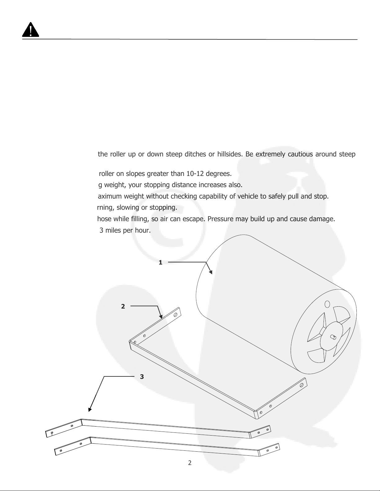
Carton Contents
1. Roller Body
2. Center Brace
3. Hitch Side Bar (2)
1
2
3

3
Ref. Qty. Description
5
6
7
8
9
10
11
12
13
14
1
2
2
4
2
6
1
8
2
1
1/2” x 2-1/4” Clevis Pin
3/8” x 2-1/4” Hex Head Bolt
3/8” x 1-1/2” Hex Head Bolt
3/8” x 1” Hex Head Bolt
3/16” Cotter Pin
5/8” Flat Washer
#14 Hitch Pin Clip
3/8” Nylock Nut
Clevis Plate
Expansion Plug
5
Parts Used During Assembly
Not Shown Full Size
6
7
8
9
10
12
11
13
14*
14
4
Assembly Instructions
Tools Required For Assembly
(1) Pair of Pliers
(2) 9/16” Wrenches
(2) 3/4” Wrenches
Optional Tools
(1) Utility Knife
(1) Hammer
Remove from Carton
Remove all parts and hardware packages from the
carton. Lay out all parts and hardware and identify
them using the illustrations on pages 2 and 3.
1. Inspect axle ends. If there is excessive plastic,
trim with knife using extreme caution.
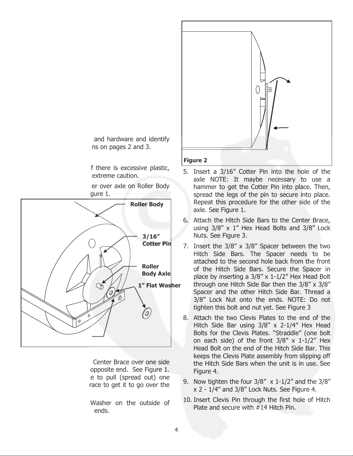
2. Place a 1” Flat Washer over axle on Roller Body
on both ends. See Figure 1.
3. Place one end of the Center Brace over one side
of the axle then the opposite end. See Figure 1.
NOTE: You my have to pull (spread out) one
end of the Center Brace to get it to go over the
axle. See Figure 2.
4. Place one 1” Flat Washer on the outside of
Center Brace on both ends.
5. Insert a 3/16” Cotter Pin into the hole of the
axle NOTE: It maybe necessary to use a
hammer to get the Cotter Pin into place. Then,
spread the legs of the pin to secure into place.
Repeat this procedure for the other side of the
axle. See Figure 1.
6. Attach the Hitch Side Bars to the Center Brace,
using 3/8” x 1” Hex Head Bolts and 3/8” Lock
Nuts. See Figure 3.
7. Insert the 3/8” x 3/8” Spacer between the two
Hitch Side Bars. The Spacer needs to be
attached to the second hole back from the front
of the Hitch Side Bars. Secure the Spacer in
place by inserting a 3/8” x 1-1/2” Hex Head Bolt
through one Hitch Side Bar then the 3/8” x 3/8”
Spacer and the other Hitch Side Bar. Thread a
3/8” Lock Nut onto the ends. NOTE: Do not
tighten this bolt and nut yet. See Figure 3
8. Attach the two Clevis Plates to the end of the
Hitch Side Bar using 3/8” x 2-1/4” Hex Head
Bolts for the Clevis Plates. “Straddle” (one bolt
on each side) of the front 3/8” x 1-1/2” Hex
Head Bolt on the end of the Hitch Side Bar. This
keeps the Clevis Plate assembly from slipping off
the Hitch Side Bars when the unit is in use. See
Figure 4.
9. Now tighten the four 3/8” x 1-1/2” and the 3/8”
x 2 - 1/4” and 3/8” Lock Nuts. See Figure 4.
10. Insert Clevis Pin through the first hole of Hitch
Plate and secure with #14 Hitch Pin.
Figure 1
Roller Body
1” Flat Washer
3/16”
Cotter Pin
Roller
Body Axle
Center Brace
Figure 2
(spread out)
Center Brace
5
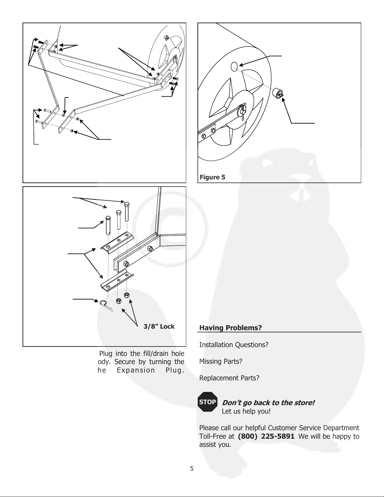
11. Insert a Expansion Plug into the fill/drain hole
on end of the Roller Body. Secure by turning the
w i n g n u t o n t h e E x p a n s i on P lu g .
Figure 4
Figure 3
3/8” Lock
Nuts
3/8” Spacer
3/8” Lock
Nuts
3/8” x 1”-1/2”
Hex Head Bolt
3/8” x 1”
Hex Head
Figure 5
3/8” x 2-1/4
Hex Head
Bolt
Clevis Pin
Hitch Plates
3/8” Lock
#14 Clevis
Pin Clip
Fill/Drain Hole
Expansion
Plug
See Figure 5
Having Problems?
Installation Questions?
Missing Parts?
Replacement Parts?
Don’t go back to the store!
Let us help you!
Please call our helpful Customer Service Department
Toll-Free at (800) 225-5891 We will be happy to
assist you.
STOP
6
Operation
Fill the Roller with amount of water or sand for
the weight recommended for your towing
equipment.
Be sure to check owner’s manual of towing
equipment to make sure that its towing capacity
is not exceeded.
For longest life, drain the Roller and leave the
Plug out when not in use.
Sand may be used in place of water to avoid risk
of freezing.
Maintenance Instructions
Always check all the hardware before use. Make
sure all hardware and components are tight and
secure.
Always keep moving parts lubricated. Lubricate
where the Axle extends through the Hitch Side
Bar when needed with light oil.
Keeping the roller clean and dry will prolong the
unit’s life.
Should rust develop, sand lightly and then paint
area with enamel paint.
9
11
4
12
13
6
Model Tank
Weight
Water Gallon
Capacity
Filled Weight
RL1848TB
82
53
522
RL1848TB
Ref No. Part Number QTY Description
1 2080TB 1 Roller Body
2 1956 1 Expansion Plug
3 2351 6 Washer 1 " Flat
4 2354 2 Cotter Pin 3/16" x 1.5"
5 2348 8 Nylock Nut 3/8"
6 1974 4 HH Bolt 3/8" x 1"
7 2081TB 1 Center Brace
8 2084TB 2 Hitch Side
9 3255 2 HH Bolt 3/8" x 2.25"
10 3254 1 Spacer 3/8" x 3/8"
11 3256 1 Clevis Pin 1/2" x 2.25"
12 1806 2 HH Bolt 3/8" x 1.5"
13 3257TB 2 Clevis Plate
14 1042 1 Hitch Pin Clip # 14

7
Parts and Support
Please do not return this product to the
store prior to contacting Precision.
At Precision Products Inc. our goal is to deliver
quality, value and outstanding service. If for any
reason our product does not meet your
expectations, please contact us and we will take
care of any problem you may have with this unit.
When ordering replacement parts please have the
model number, part description, part number,
inspector Number and Date on Box, available so
that we can best serve you.
1 (800) 225-5891
www.precisionprodinc.com
STOP
3 1
5
5
3
7
14
10
8
9
11
4
12
4
6
13
5
6
2
8
Manufacture’s Limited Warranty for Pull Behind Accessories
The limited warranty set forth below is given by Precision
Products Incorporated with respect to new merchandise
purchased and used in the United States, its possessions
and territories.
Precision Products Incorporated warranties the product(s)
listed against defects in material and workmanship, and
will at our option, repair or replace, free of charge, any
part found to be defective in materials or
workmanship. This limited warranty shall only apply if
this product has been assembled, operated, and
maintained in accordance with the owner’s manual
furnished with the product, and has not been subject to
misuse, abuse, neglect, accident, improper maintenance,
alteration, vandalism, theft, fire, water, or damage
because of other peril or natural disaster.
Normal wear parts or components thereof are subject to
separate terms as follows: All normal wear parts or
component failures will be covered on the product for a
period of one year. Parts found to be defective within the
warranty period will be replaced at our expense. Our
obligation under this warranty is expressly limited to the
replacement or repair, at our option, of parts found to be
defective in material and workmanship.
Contacting Service
Warranty parts replacements are available, only with
Proof of Purchase, through our Customer Service
Department. Call 1 (800) 225-5891
This limited warranty does not provide coverage in the
following cases:
1. Routine maintenance items such as lubricants and
filters.
2. Normal deterioration of the exterior finish due to use
or exposure.
3. Transportation and/or labor charges.
No implied warranty, including any implied warranty of
merchantability of fitness for a particular purpose, applies
after the applicable period of express written warranty
above as to the part as identified below. No other
express warranty whether written or oral, except as
mentioned above, given by any person or entity,
including a dealer or retailer, with respect to any product,
shall bind Precision Products Inc. During the period of the
warranty, the exclusive remedy is repair or replacement
of the product as set forth above.
The provisions as set forth in this warranty provide the
sole and exclusive remedy arising from the sale.
Precision Products Inc. will not be liable for incidental or
consequential loss or damage including, without
limitation, expenses incurred for substitute or
replacement lawn care services or for rental expenses to
temporarily replace a warranted product.
Some states do not allow the exclusion or limitation of
incidental or consequential damages, or limitations on
how long an implied warranty lasts, so the above
exclusions or limitations may not apply to you.
During the warranty period, the exclusive remedy is
replacement of the part. In no event shall recovery of
any kind be greater that the amount of the purchase
price of the product sold. Alteration of safety features of
the product shall void this warranty. You assume the risk
and liability for loss, damage, or injury to you and your
property and/or to others and their property arising out
of the misuse or inability to use this product.
This limited warranty shall not extend to anyone other
than the original purchaser or to the person for whom it
was purchased as a gift.
Local Law to this Warranty
This limited warranty gives you specific legal rights, and
you may also have other rights which vary from state to
state.
Warranty Period
The Warranty period stated below begins with the Proof
of Purchase. Without the proof of purchase, the
Warranty period begins from the date of manufacture
determined by the serial number manufacturing date.
Poly Lawn Roller Warranty Period
The warranty period for this unit is as follows: All part are
cover one year from date of sale.
Other Precision Lawn And Garden Equipment manuals


