Precision TA500 User manual
Owner’s Manual | TA500 | 40”Spike Aerator
Manual Contents
Safety Instructions .......................................................... 2
Assembly ............................................................................ 4-5
Operation........................................................................... 5
Maintenance ..................................................................... 5
Parts...................................................................................... 6-7
Warranty ............................................................................. 8
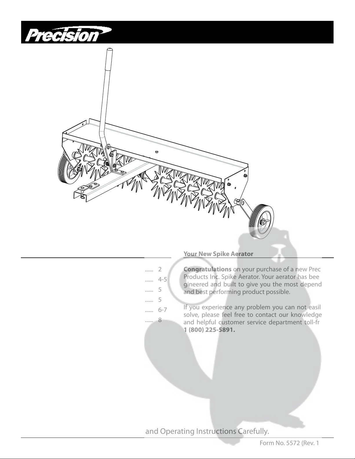
Your New Spike Aerator
Congratulations on your purchase of a new Precision
Products Inc. Spike Aerator. Your aerator has been en-
gineered and built to give you the most dependable
and best performing product possible.
If you experience any problem you can not easily re-
solve, please feel free to contact our knowledgeable
and helpful customer service department toll-free at
1 (800) 225-5891.
Caution: Read all Safety Instructions and Operating Instructions Carefully.
Form No. 5572 (Rev. 10/11)

Safety Instructions
All power equipment can cause injury or property damage if operated improperly. Please read and observe the
following safety rules and exercise caution at all times when operating equipment.
• Read and understand your tractor owner’s manual and towing safely rules. Know how to operate your tractor before using any attachment.
• Never allow children to operate the towing vehicle. Do not allow adults to operate the vehicle without having read the owner’s manual or
receiving proper instruction.
• Do not allow anyone to ride or sit on tow behind equipment during operation.
• Keep people, children and animals at a safe distance.
• Always wear substantial footwear. Do not wear loose tting clothing that may get caught in moving parts.
• This unit may have sharp points. Handle with care.
• Keep your eyes and mind on your vehicle/attachment and area being covered. Do not let yourself be distracted.
• Stay alert for holes in the terrain and other hidden hazards.
• Tractor braking and stability may be aected with the attachment of this unit. Be aware of changing conditions on slopes. Refer to safety rules
in your tractor owner’s manual concerning safe operation on slopes. Stay O Steep Slopes.
• Always operate up and down a slope, never across the face of a slope.
• This equipment should be operated at reduced speed(s) on rough terrain, along creeks and ditches and on hillsides, to prevent tipping or loss
of control.
• Do not operate close to creeks, ditches or public highways.
• Always begin with the transmission in rst (low) gear and engine at low speed, and gradually increase speed as conditions permit.
• Keep the vehicle and attachment in good operating condition and keep safety devices in place.
• Keep all nuts, bolts and screws tight to be sure the equipment is in safe working condition.
• The vehicle and attachment should be stopped and inspected for damage after striking a foreign object. Any damage should be repaired
before restarting and operating the equipment.
• Follow the maintenance instructions as outlined in this owner’s manual.
• Should not be towed at more than 4 miles per hours.
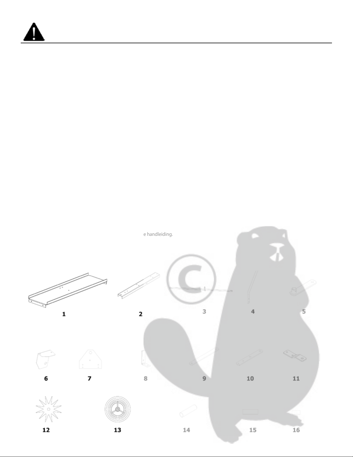
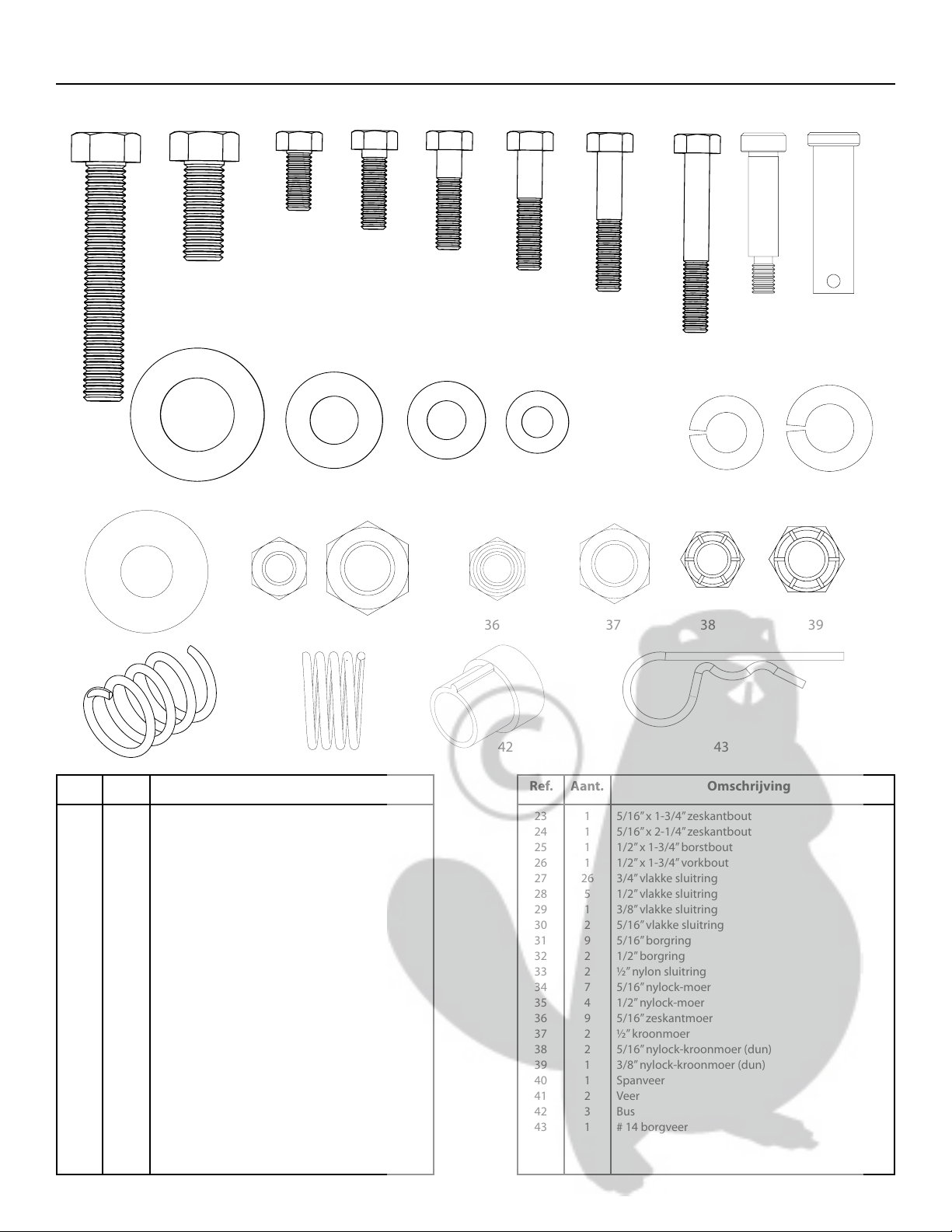
Carton Contents
2

Shown Full Size
25
201918
17
2423
2221
27
26
3534
33
3231302928
424140
39383736
43
1
2
3
4
5
6
7
8
9
10
11
12
13
14
15
16
17
18
19
20
21
22
23
24
25
26
27
28
29
30
31
32
33
34
35
36
37
38
39
40
41
42
43
Ref. Ref.Qty. Qty.Description Description
1
1
1
1
2
1
2
1
1
1
1
11
2
1
9
2
2
1
9
2
1
2
1
1
1
1
26
5
1
2
9
2
2
7
4
9
2
2
1
1
2
3
1
Base Plate
Tow Bar
Axle
Handle
Wheel Brackets
Center Plate
End Plate
Handle Stop
Lever Link
Linkage Bar
Clevis Plate
Aerator Blade
Wheel
Handle Grip
1”x 3” Spacer
1”x 2” Spacer
1/2”x 3” Hex Head Bolt
1/2”x 1-1/2” Hex Head Bolt
5/16”x 3/4” Hex Head Bolt
5/16”x 1” Hex Head Bolt
5/16”x 1-1/4” Hex Head Bolt
5/16”x 1-1/2” Hex Head Bolt
5/16”x 1-3/4” Hex Head Bolt
5/16”x 2-1/4” Hex Head Bolt
1/2”x 1-3/4” Shoulder Bolt
1/2”x 1-3/4” Clevis Pin
3/4”Flat Washer
1/2”Flat Washer
3/8”Flat Washer
5/16”Flat Washer
5/16”Lock Washer
1/2”Lock Washer
1/2”Nylon Washer
5/16”Nylock Nut
1/2”Nylock Nut
5/16”Hex Head Nut
1/2”Jam Nut
5/16”Nylock Nut (thin) Jam
3/8”Nylock Nut (thin) Jam
Compression Spring
Spring
Bushing
#14 Hitch pin Clip
3

Assembly Instructions
Tools Required for Assembly
Minimum
(2) Adjustable Wrenches
(1) Allen Wrench
Remove from Carton
Remove and layout all parts and hardware packages from the carton. Identify them using the illustrations on
pages 2 and 3.
1. Place the Base Plate on a at surface, insert a 5/16” x 3/4” Hex Head Bolt into the top right hole, then insert the
bolt into the corresponding hole of the Tow Bar. Place a 5/16” Lock Washer onto the bolt and secure with a 5/16”
Hex Head Nut. Next align the Center Plate with the two remaining holes. Insert 5/16”x 3/4”Hex Head bolts through
the holes in the Base Plate and the corresponding holes of the Tow Bar and Center Plate. Place a 5/16”Lock Washer
onto each bolt and secure with 5/16”Hex Head Nuts. Insert a 3/4” Axle Bushing into the Center Plate. See Figure 1.
Figure 1
5/16” Hex Head Bolt
Base Plate
Center Plate
Tow Bar
3/4” Axle Bushing
5/16” Lock Washer
5/16” Hex Head Nut
5/16” x 2-1/4”
Hex Head Bolt
5/16” Nylock
Nut
Center Plate
Base Plate
3/4”Axle Bushing
Tow Bar
5/16”Hex Head Bolt
5/16”Lock Washer
5/16”Hex Head Nut
Figure 1
4

Figure 2
3/4” Flat Washer
1” x 2” Spacer
Center Plate
3/4” Axle
Bushing
3/4”Axle
Bushing
Center Plate
1”x 2” Spacer
3/4”Flat Washer
Figure 2
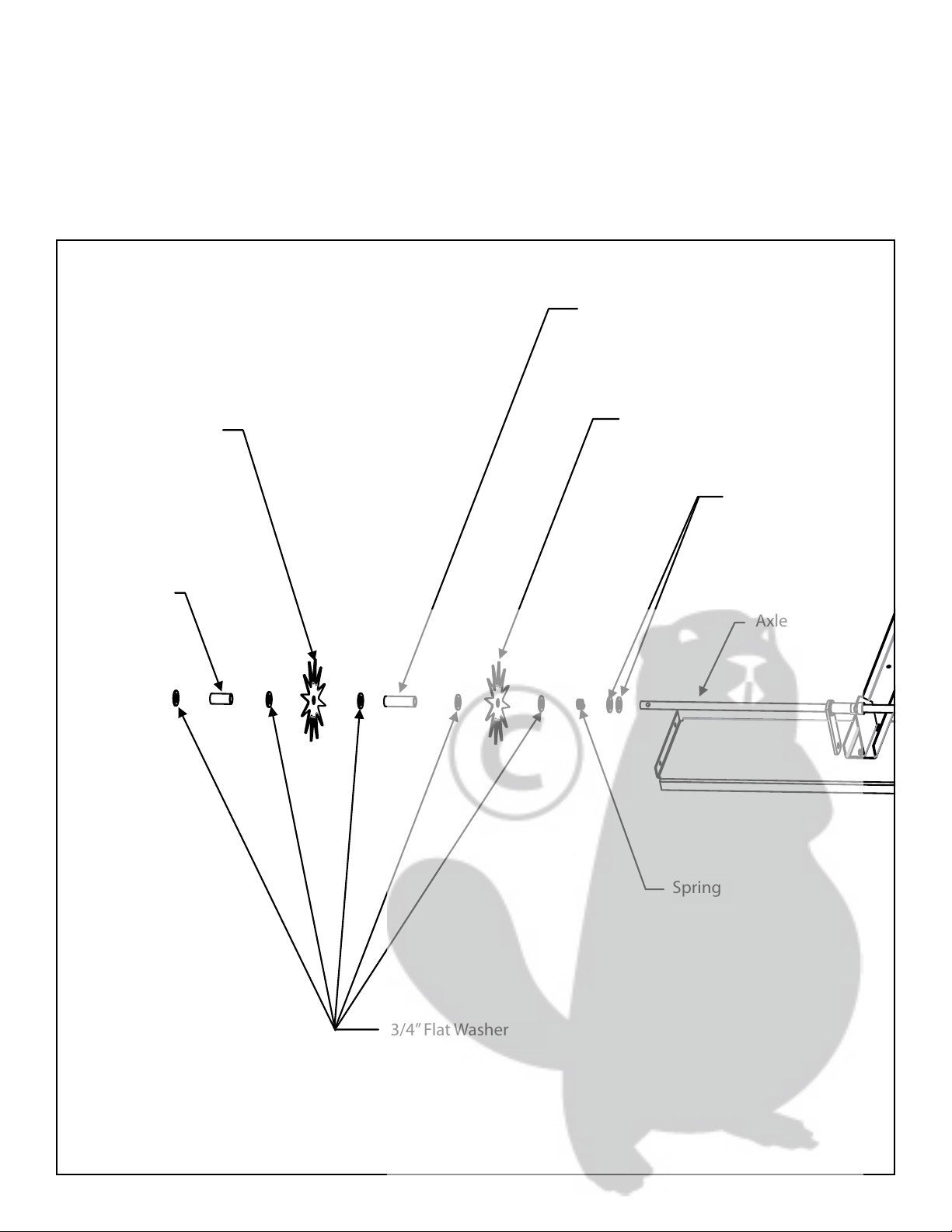
3.. On the short side of the Axle, place two 3/4”Flat Washer onto the Axle, followed by an Axle Spring and then an-
other 3/4” Flat Washer, followed by an Aerator Star and then another 3/4”Flat Washer onto the Axle. Place a 1” x 3”
Spacer onto the Axle, a 3/4”Flat Washer another Aerator Star and another 3/4”Flat Washer repeat this process three
more times. Now place a 1”x 2” Spacer onto the Axle followed by another 3/4”Flat Washer. See Figure 3.
5
3.. On the short side of the Axle, place two 3/4”Flat Washer onto the Axle, followed by an Axle Spring and then an-
other 3/4” Flat Washer, followed by an Aerator Star and then another 3/4”Flat Washer onto the Axle. Place a 1” x 3”
Spacer onto the Axle, a 3/4”Flat Washer another Aerator Star and another 3/4”Flat Washer repeat this process three
more times. Now place a 1”x 2” Spacer onto the Axle followed by another 3/4”Flat Washer. See Figure 3.
Figure 3
1” x 2” Spacer
3/4” Flat Washer
1” x 3” Spacer
Aerator Star
Spring
3/4” Flat Washer
Axle
Aerator Star
1”x 2” Spacer
Aerator Star
3/4”Flat Washer
Spring
Axle
3/4”Flat Washer
Aerator Star
1”x 3” Spacer
Figure 3
6

4. Insert a 3/4” Axle Bushing into the End Plate and place the Bushing and End Plate onto the Axle. Insert a 5/16” x
3/4” Hex Head Bolt into one of the end holes in the Base Plate. Then insert the bolt into the holes in the End Plate,
place a 5/16”Lock Washer onto the bolt, loosely attach a 5/16”Hex Head Nut onto the bolt at this time. Repeat this
process on the other side. Now alternating back and forth between the two bolts tighten the nuts. This will slowly
increase the tension on the Axle Spring, until this side is tight and properly aligned. See Figure 4.
Figure 4
5/16” x 3/4” Hex Head
Bolt
5/16” Hex Head Nut
5/16” Lock Washer
End Plate
3/4” Axle Bushing
Axle
5/16”Lock Washer
End Plate
3/4”Axle Bushing
5/16”x 3/4” Hex Head
Bolt
5/16”Hex Head Nut
Figure 4
Axle
7
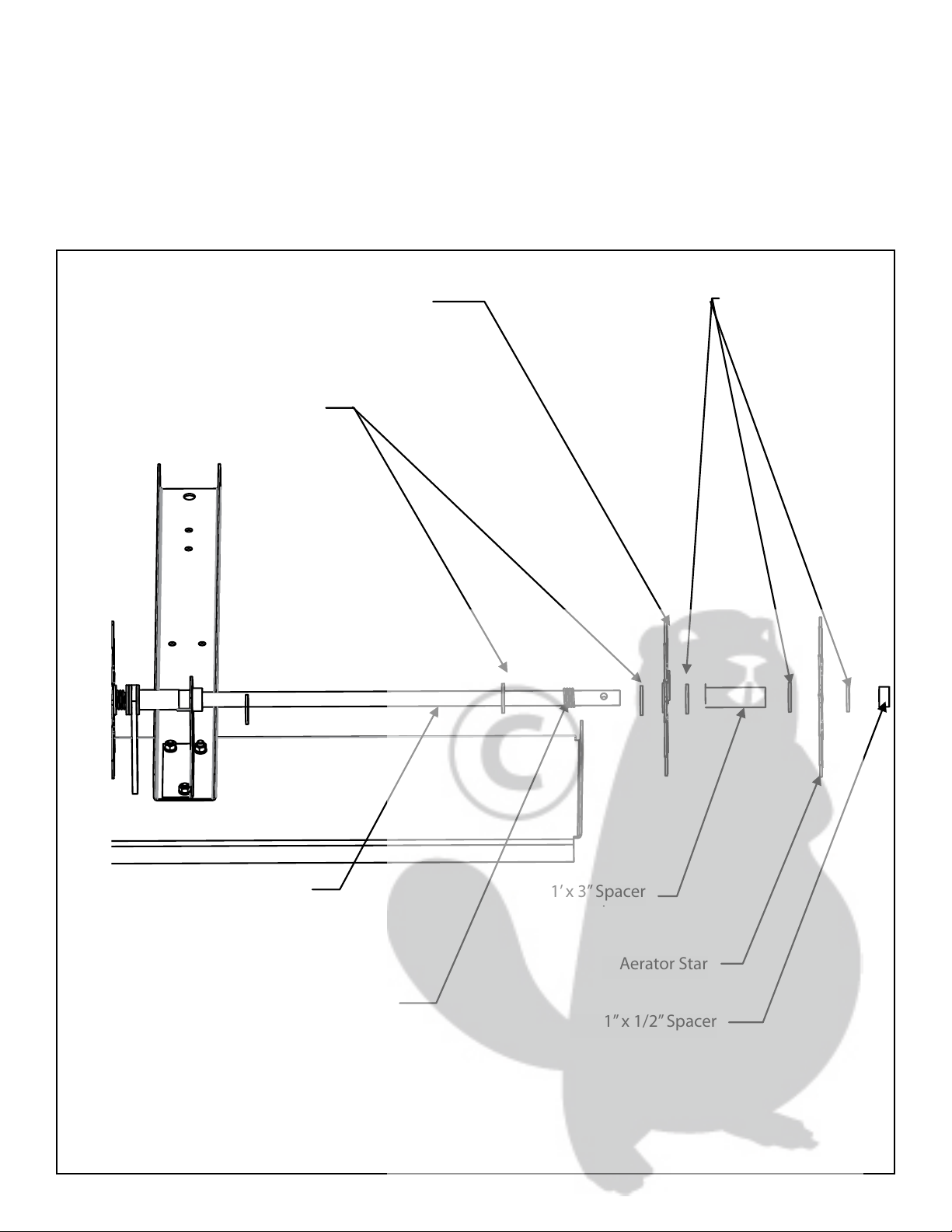
5. . On the long side of the Axle place a 3/4” Flat Washer followed by an Axle Spring and then another 3/4” Flat
Washer. Followed by a 3/4” Flat Washer an Aerator Star, another 3/4” Flat Washer and a 1” x 3” Spacer. Repeat the
process ve more times. Then place a 1”x 1/2” Spacer onto the Axle. See Figure 5.
Figure 5
Axle
Aerator Star
1” x 1/2” Spacer
Spring
3/4” Flat Washer
1’ x 3” Spacer
3/4” Flat Washer
Aerator Star 3/4”Flat Washer
3/4”Flat Washer
Aerator Star
Spring 1”x 1/2” Spacer
Figure 5
1’x 3” Spacer
Aerator Star
Axle
8

6. Insert a 3/4” Axle Bushing into the End Plate and place the Bushing and End Plate onto the Axle. Insert a 5/16” x
3/4” Hex Head Bolt into one of the end holes in the Base Plate. Then insert the bolt into the holes in the End Plate,
place a 5/16”Lock Washer onto the bolt, loosely attach a 5/16”Hex Head Nut onto the bolt at this time. Repeat this
process on the other side. Now alternating back and forth between the two bolts tighten the nuts. This will slowly
increase the tension on the Axle Spring, until this side is tight and properly aligned.
Figure 6
5/16” x 3/4” Hex
Head Bolt
Axle
5/16” Hex Head Nut
5/16” Lock Washer
End Plate
3/4” Axle Bushing
5/16”Hex Head Nut
5/16”x 3/4” Hex
Head Bolt
5/16”Lock Washer
Figure 6
3/4”Axle Bushing
End Plate
Axle
9
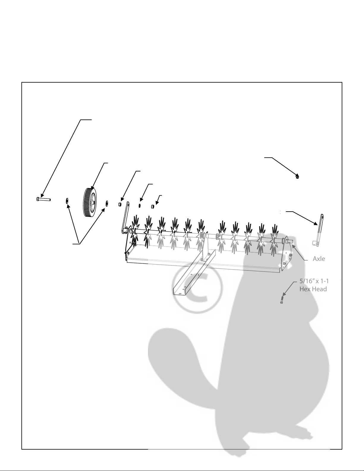
7. Align the hole of the Wheel Bracket with the hole in the Axle. Insert a 5/16”x 1-1/2” Hex Head Bolt into the hole
in the Wheel Bracket and Axle. Secure with a 5/16” Nylock Nut. Repeat process on the other side. Place a 1/2” Flat
Washer onto a 1/2” x 3” Hex Head Bolt, followed by a Wheel and then another 1/2” Flat Washer and secure with a
1/2” Nylock Nut (Do not over tighten or the Wheel will not turn). Insert this assembly into the hole in the Wheel
Bracket, them place a 1/2” Lock Washer onto the bolt and secure with a 1/2” Jam Nut. Repeat the process on the
other side. See Figure 7.
Figure 7
5/16” Nylock Nut
5/16” x 1-1/2”
Hex Head Bolt
Wheel Bracket
1/2” x 3” Hex
Head Bolt
1/2” Flat Washer
Wheel
Axle
1/2” Jam Nut
1/2” Lock Washer
1/2” Nylock Nut
1/2”x 3” Hex
Head Bolt
5/16”Nylock Nut
5/16”x 1-1/2”
Hex Head Bolt
1/2”Nylock Nut
1/2”Lock Washer
1/2”Jam Nut
Wheel
Wheel Bracket
1/2”Flat Washer
Axle
Figure 7
10

8. Align the two holes of the Tow Bar and Handle Brace as shown. Insert a 5/16” x 1” Hex Head Bolt into one of the
holes in the Handle BRACE and then through the corresponding hole in the Tow Bar, place a 5/16”Flat Washer onto
the bolt, and secure with a 5/16” Nylock Nut. Repeat process on the next hole. Insert a 5/16” x 3/4” Hex Head Bolt
into one of the two smaller holes on the Clevis Plate and then into the corresponding hole in the Tow Bar, place a
5/16”Lock Washer onto the bolt and secure with a 5/16”Hex Head Nut. Repeat process on the next hole. Insert the
Clevis Pin through the larger front hole of the Clevis Plate and through the hole in the Tow Bar and secure with the
Hitch Pin Clip. Screw the 5/16”Nylock Jam Nut onto the 5/16”x 1-1/4 Hex Head Bolt, leaving enough room for the
Lever Link to t between the head and the nut. Insert the bolt into the hole in the side of the Tow Bar and secure
with a 5/16”Nylock Nut. See Figure 8.
Figure 6
Handle Brace
5/16” Nylock Nut
5/16” Flat Washer
Clevis
Pin
Clevis Plate
5/16” x 1” Hex Head Bolt
5/16” x 3/4” Hex Head
Bolt
Hitch Pin Clip
5/16” Hex Head Nut
5/16” Lock
Washer
Tow Bar
5/16”Flat Washer
5/16”Nylock Nut
5/16”Hex Head Nut
Hitch Pin Clip
5/16”Lock
Washer
Tow Bar
5/16”x 3/4” Hex Head
Bolt
5/16”x 1” Hex Head Bolt
Clevis Plate
Handle Brace
Clevis
Pin
Figure 6
11
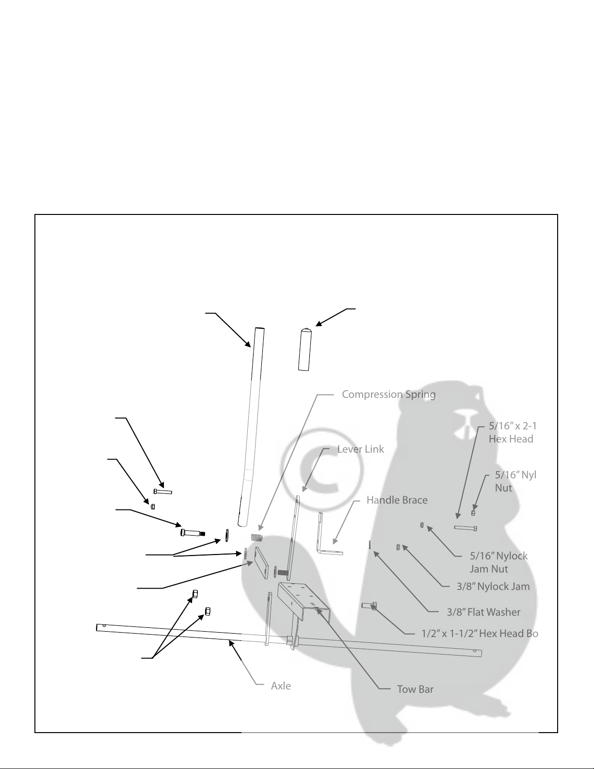
5/16” Nylock
Nut
5/16” x 2-1/4”
Hex Head Bolt
5/16” Nylock
Nut
Linkage Bar
Compression Spring
5/16” x 1-3/4”
Hex Head Bolt
Handle Handle Grip
3/8” Nylock Jam Nut
5/16” Nylock
Jam Nut
Handle Brace
1/2” Nylon Washer
1/2” x 1-3/4”
Shoulder Bolt
1/2” x 1-1/2” Hex Head Bolt
1/2” Nylock Nut
Tow Bar
Lever Link
Figure 7
Axle
3/8” Flat Washer
5/16”x 2-1/4”
Hex Head Bolt
5/16”Nylock
Nut
5/16”Nylock
Jam Nut
3/8”Nylock Jam Nut
3/8”Flat Washer
1/2”x 1-1/2” Hex Head Bolt
1/2”Nylock Nut
Linkage Bar
1/2”Nylon Washer
5/16”Nylock
Nut
1/2”x 1-3/4”
Shoulder Bolt
5/16”x 1-3/4”
Hex Head Bolt
Tow Bar
Axle
Handle Grip
Compression Spring
Lever Link
Handle Brace
Handle
Figure 7
7. Place a 1/2” Flat Washer onto the 1/2” x 1-3/4” Shoulder Bolt, followed by the Compression Spring, insert it into
the 1/2” hole in the Center of the Lever Link and into the Handle Brace, a 3/8” Flat Washer and secure with a 3/8”
Nylock Jam Nut. Place a 1/2”Nylon Washer onto the threaded stud on the bottom of the Leverage Bar, followed by
the Linkage Bar, secure with a 1/2”Nylock Nut (When nut is snug, back-o one half turn) . Insert the 1/2”x1-1/2”Hex
Head Bolt into the other end of the Linkage Bar, followed by a 1/2”Nylon Washer, then into the hole in the Axle Link
and secure with a 1/2” Nylock Nut. Place the Handle Grip onto the Handle. Put the 5/16” Nylock Jam Nut onto the
5/16” x 2-1/4” Hex Head Bolt leaving about 1/2”Space between the Head of the bolt and the top of the nut. Insert
the bolt into the second hole from the top on the Linkage Bar, then into the corresponding hole of the Handle and
secure with a 5/16” Nylock Nut. Insert a 5/16” x 1-3/4” Hex Head Bolt into the top hole of the Linkage Bar, through
the corresponding hole in the Handle and secure with a 5/16” Nylock Nut. See Figure 7.
12
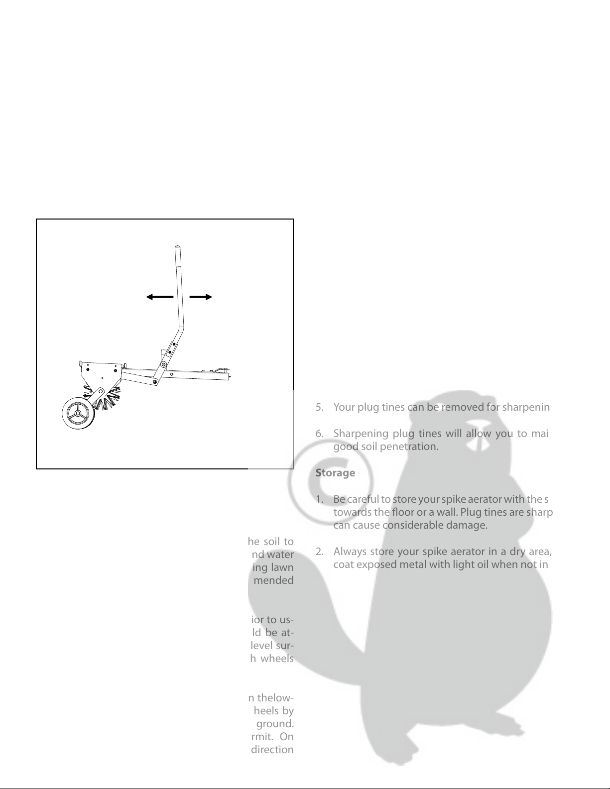
Raising/Lowering your Spike Aerator
1. Attach the unit to your tractor on a level surface us-
ing the provided clevis pin and clevis pin clip.
2. Once you enter the grassy surface, lower the aera-
tor for operation, move the handle to the side and
push back to engage the spikes.
3. When complete, pull handle forward and lock to
raise the unit and engage the wheels.
See Figure 8.
Using the Spike Aerator
Aerating involves cutting small holes into the soil to
create small reservoirs allowing air, fertilizer, and water
to reach the grass or plant’s roots. The following lawn
preparation and aerator operation is recommended
for optimal performance.
Mow the lawn and remove grass clippings prior to us-
ing the plug aerator. Your plug aerator should be at-
tached to your riding mower or tractor on a level sur-
face such as a driveway or garage oor with wheels
engaged.
Once you are on the grass, have the tractor in thelow-
est forward speed and then disengage the wheels by
moving the handle out of the locked posithe ground.
Speed can be increased as conditions permit. On
slopes, always operate in an up and down direction
only. Overlapping passes can be done to increase the
density of the spike point pattern.
DO NOT make sharp turns while the plug tines are
engaged in the ground as this will damage the lawn.
Weight can be placed on the top plate to increase the
depth of plug tines penetration. Weight may be need-
ed for many applications, but DO NOT exceed the max-
imum weight of 100 lbs. The plate has been designed
to hold concrete blocks. Secure the blocks with suit-
able binding material such as rubber tie down straps
or wire. Not for use with Zero Turn Radius Mowers.
Maintenance
1. Before each use, check all nuts and bolts for tight-
ness.
2. Clean after each use to prevent rust. The key to
years of trouble-free service is to keep your unit
clean and dry.
3. If rust should develop, sand lightly and then paint
area with enamel.
4. Periodically check all moving parts for free move-
ment and if necessary, lubricate with oil.
5. Your plug tines can be removed for sharpening.
6. Sharpening plug tines will allow you to maintain
good soil penetration.
Storage
1. Be careful to store your spike aerator with the spikes
towards the oor or a wall. Plug tines are sharp and
can cause considerable damage.
2. Always store your spike aerator in a dry area, and
coat exposed metal with light oil when not in use.
Raising and lowering
Lower Raise
Figure 8
Raising and lowering
Lower Raise
Figure 8
13
20 27 1
7
31
36
15
12
12
16
41
13
23
18
28
35 34
37
5
32
11
42
6
20
20
21
23
29 8
26
14
40
4
33 3
39
24
29
35
38
25
36
38
22
43
31
30
36
31
1
34
36
2
9
17
19
14

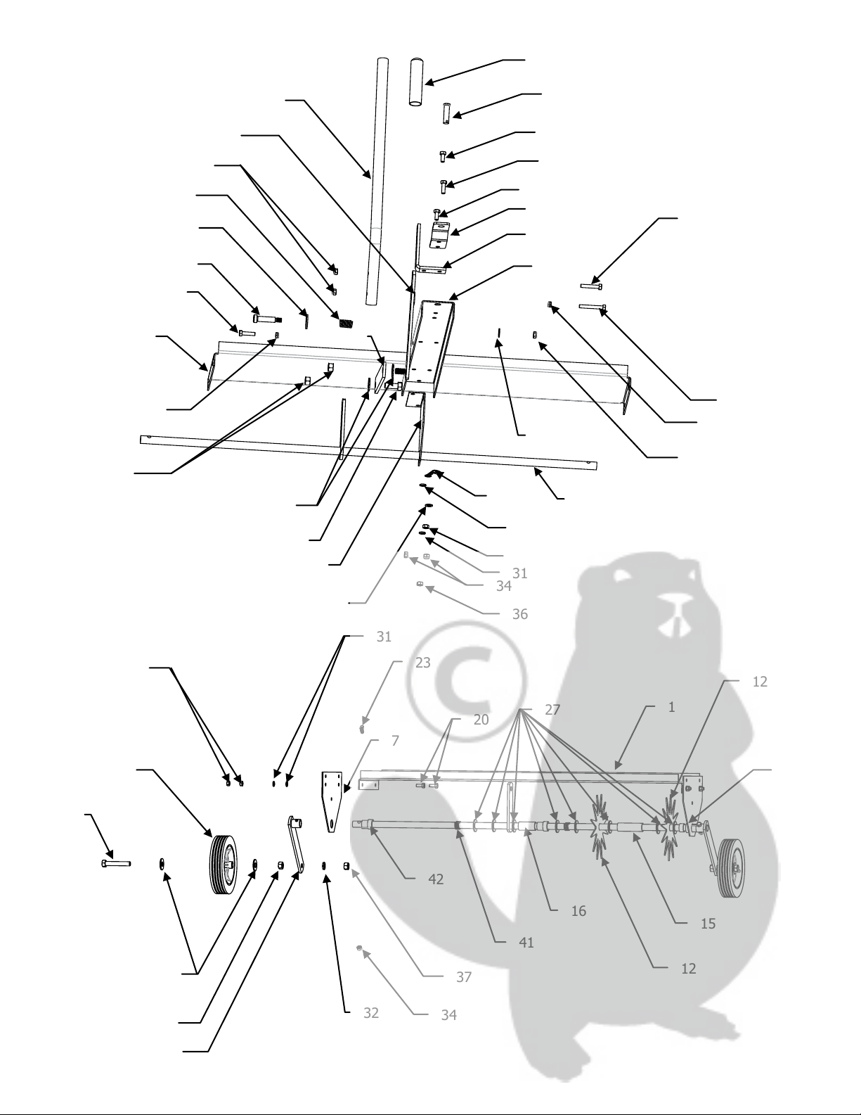
Parts and Support
Please do not return this product to
the store prior to contacting Precision.
At Precision Products Inc. our goal is to deliver qual-
ity, value and outstanding service. If for any reason our
product does not meet your expectations, please con-
tact us and we will take care of any problem you may
have with this unit.
When ordering replacement parts please have the
model number, part description, part number, inspec-
tor number and date on the box, available so that we
can best serve you.
1 (800) 225-5891
www.precisionprodinc.com
Precision Products Inc.
316 Limit St.
Lincoln IL 62656
No. Part No. Qty. Description
14020GY 1 Base Plate
25864GY 1 Tow Bar
35870 1 A x l e
45865GY 1 Handle
55568GY 2 Wheel Bracket
65869GY 1 Center Plate
74019GY 2 End Plates
85866GY 1 Handle Brace
94263G 1 Lever Link
10 4240G 1 Linkage Bar
11 1243GY 1 Clevis Plate
12
4025GYOS
11 Aerator Blade
13 3150 2 Wheel
14 3042 1 Handle Grip
15 4470 9 1”x 3” Spacer
16 4029GY 2 1’x 2” Spacer
17 4271 2 1/2”x 3” Hex Head Bolt
18 5583 1 1/2”x 1-1/2” Hex Head Bolt
19 1248 9 5/16”x 3/4” Hex Head Bolt
20 3738 2 5/16”x 1” Hex Head Bolt
21 4281 2 5/16”x 1-1/4” Hex Head Bolt
22 4014 1 5/16”x 1-1/2” Hex Head Bolt
23 2051 1 5/16”x 1-3/4” Hex Head Bolt
24 1752 1 5/16”x 2-1/4” Hex Head Bolt
25 4011 1 1/2”x 1-3/4” Shoulder Bolt
26 1840 1 1/2”x 1-3/4” Clevis Pin
27 1264 26 3/4”Flat Washer
28 1506 4 1/2”Flat Washer
29 1278 1 3/8”Flat Washer
30 1044 2 5/16”Flat Washer
31 1276 9 5/16”Lock Washer
32 3414 2 1/2”Lock Washer
33 5589 2 1/2”Nylon Washer
34 1749 7 5/16”Nylock Nut
TA500
35 4327 4 1/2” Nylock Nut
36 1275 9 5/16” Hex Head Nut
37 4324 2 1/2” Jam Nut
38 5591 2 5/16” Nylock Jam Nut (thin)
39 5590 1 3/8” Nylock Jam Nut (thin)
40 4272 1 Compression Spring
41 4024 2 Spring (Axle)
42 4051 3 Bushing 3/4” (Axle)
43 1042 1 #14 Hitch Pin Clip
15

Manufacture’s Limited Warranty for Pull Behind Accessories
The limited warranty set forth below is given by Preci-
sion Products Incorporated with respect to new mer-
chandise purchased and used in the United States, its
possessions and territories.
Precision Products Incorporated warranties the
product(s) listed against defects in material and work-
manship, and will at our option, repair or replace, free
of charge, any part found to be defective in materials
or workmanship. This limited warranty shall only ap-
ply if this product has been assembled, operated, and
maintained in accordance with the owner’s manual
furnished with the product, and has not been sub-
jected to misuse, abuse, neglect, accident, improper
maintenance, alteration, vandalism, theft, re, water,
or damage because of other peril or natural disaster.
Normal wear parts or components thereof are subject
to separate terms as follows: All normal wear parts or
component failures will be covered on the product for
a period of one year. Parts found to be defective within
the warranty period will be replaced at our expense.
Our obligation under this warranty is expressly limited
to the replacement or repair, at our option, of parts
found to be defective in material and workmanship.
Contacting Service
Warranty parts replacements are available, ONLY WITH
PROOF OF PURCHASE, through our Customer Service
Department.
Call 1 (800) 225-5891
This limited warranty does not provide coverage in
thefollowing cases:
1. Routine maintenance items such as lubricants and
lters.
2. Normaldeteriorationoftheexteriornishduetouse
or exposure.
3. Transportation and/or labor charges.
No implied warranty, including any implied warranty
of merchantability of tness for a particular purpose,
applies after the applicable period of expressed writ-
ten warranty above as to the part as identied below.
No other expressed warranty, whether written or oral,
except as mentioned above, given by any person or
entity, including a dealer or retailer, with respect to any
product, shall bind Precision Products Inc. during the
period of the warranty, the exclusive remedy is repair
or replacement of the product as set forth above. The
provisions as set forth in this warranty provide the sole
and exclusive remedy arising from the purchase
Precision Products Inc. will not be liable for incidental
or consequential loss or damage including, without
limitation, expenses incurred for substitute or replace-
ment lawn care services, or for rental expenses to tem-
porarily replace a warranted product.
Some states do not allow the exclusion or limitation of
incidental or consequential damages, or limitations on
how long an implied warranty lasts, so the above ex-
clusions or limitations may not apply to you.
During the warranty period, the exclusive remedy is
replacement of the part. In no event shall recovery of
any kind be greater that the amount of the purchase
price of the product sold. Alteration of safety features
of the product shall void this warranty. You assume the
risk and liability for loss, damage, or injury to you and
your property and/or to others and their property aris-
ing out of the misuse or inability to use this product.
This limited warranty shall not extend to anyone other
than the original purchaser or to the person for whom
it was purchased as a gift.
Local Law to this Warranty
This limited warranty gives you specic legal rights,
and you may also have other rights which vary from
state to state.
Warranty Period
The warranty period stated below begins with the
Proof of Purchase. Without the proof of purchase, the
warranty period begins from the date of manufacture.
Product Warranty Period
The warranty period for this product is as follows: All
parts are covered for 1 year.
16

Handleiding | PA500 | 40” Puntbeluchter
Inhoud van de handleiding
Veiligheidsinstructies .................................................... 2
Montage ............................................................................ 4-5
Bediening .......................................................................... 5
Onderhoud ....................................................................... 5
Onderdelen ...................................................................... 6-7
Garantie .............................................................................. 8
Uw nieuwe puntbeluchter
Gefeliciteerd met uw aankoop van een nieuwe Preci-
sion Products, Inc. Puntbeluchter. Uw beluchter werd
ontworpen en gemaakt om u het meest betrouwbare
en best presterend product te bieden.
Indien u een probleem ondervindt dat u niet
kan oplossen, contacteer dan gratis onze
bekwame en behulpzame klantendienst
1 (800) 225-5891.
Waarschuwing: Lees alle veiligheidsinstructies en bedieningsinstructies door.
Form. nr. 5572(Rev. 10/11)
Veiligheidsinstructies
Alle elektrische apparaten kunnen verwondingen of schade aan materiaal toebrengen indien ze niet correct worden
gebruikt. Lees en houd u aan volgende veiligheidsregels en wees altijd voorzichtig wanneer u apparaten bedient.
• Lees de handleiding van uw tractor en houd u aan de veiligheidsregels voor slepen. U moet weten hoe u uw tractor moet bedienen voordat u hulp-
stukken aankoppelt.
• Laat kinderen nooit het sleepvoertuig bedienen. Laat geen volwassenen het voertuig bedienen zonder dat ze de handleiding hebben gelezen of
zonder dat ze voldoende instructies hebben gekregen.
• Laat niemand rijden met of zitten op de installatie tijdens gebruik.
• Hou alle mensen, kinderen en dieren op een veilige afstand.
• Draag altijd stevige schoenen. Draag geen loszittende kledingsstukken die vast kunnen raken in de bewegende onderdelen.
• Deze unit kan scherpe uiteindes hebben. Met zorg behandelen.
• Houd uw ogen en gedachten bij uw tractor/hulpstuk en de zone die moet worden behandeld. Laat u niet aeiden.
• Wees alert voor gaten in het terrein en andere verborgen gevaren.
• Het remmen en de stabiliteit van de tractor kan worden beïnvloed door het aanhangen van deze unit. Let op veranderende omstandigheden op
hellingen. Kijk in de veiligheidsregels in de handleiding van uw tractor betreende de veilige handeling op hellingen. Blijf weg van steile hellingen.
• Ga op een helling steeds op en neer, nooit dwars over het oppervlak van de helling.
• De uitrusting moet worden gebruikt op laag tempo op ruwe terreinen, langs beekjes en sloten en op hellingen om omslaan of verlies van controle
te vermijden.
• Niet gebruiken in de buurt van beekjes, greppels of openbare snelwegen.
• Begin altijd met de aandrijving in de eerste (lage) versnelling en de motor op lage toeren, versnel geleidelijk aan in de mate dat de omstandigheden
het toelaten.
• Houd het voertuig en het hulpstuk in goede staat en houd de veiligheidsmiddelen op hun plaats.
• Laat alle moeren, bouten en schroeven vastgedraaid om zeker te zijn dat het apparaat veilig is voor gebruik.
• Thet voertuig en het hulpstuk moeten worden gestopt en gecontroleerd op schade wanneer een vreemd object wordt geraakt. Enige schade moet
worden hersteld voor opnieuw op te starten en verder te gaan met het gebruik van het apparaat.
• Volg de onderhoudsinstructies zoals beschreven in deze handleiding.
• Er mag niet worden gesleept aan meer dan 6 km/u.
Inhoud van de doos
2
Weergegeven op ware grote
25
201918
17
2423
2221
27
26
3534
33
3231302928
424140
39383736
43
1
2
3
4
5
6
7
8
9
10
11
12
13
14
15
16
17
18
19
20
21
22
23
24
25
26
27
28
29
30
31
32
33
34
35
36
37
38
39
40
41
42
43
Ref. Ref.Aant. Aant.Omschrijving Omschrijving
1
1
1
1
2
1
2
1
1
1
1
11
2
1
9
2
2
1
9
2
1
2
1
1
1
1
26
5
1
2
9
2
2
7
4
9
2
2
1
1
2
3
1
Basisplaat
Sleepstang
As
Hendel
Wielsteunen
Centrale plaat
Eindplaat
Hendelstop
Hefboomverbindingsstuk
Verbindingsplaat
Vorkplaat
Blad voor beluchting
Wiel-
Handvat
1”x 3” tussenstuk
1”x 2” tussenstuk
½”x 3” zeskantbout
1/2”x 1-1/2” zeskantbout
5/16”x 3/4” zeskantbout
½”x 1” zeskantbout
5/16”x 1-1/4” zeskantbout
5/16”x 1-1/2” zeskantbout
5/16”x 1-3/4” zeskantbout
5/16”x 2-1/4” zeskantbout
1/2”x 1-3/4” borstbout
1/2”x 1-3/4” vorkbout
3/4”vlakke sluitring
1/2”vlakke sluitring
3/8”vlakke sluitring
5/16”vlakke sluitring
5/16”borgring
1/2”borgring
½”nylon sluitring
5/16”nylock-moer
1/2”nylock-moer
5/16”zeskantmoer
½”kroonmoer
5/16”nylock-kroonmoer (dun)
3/8”nylock-kroonmoer (dun)
Spanveer
Veer
Bus
# 14 borgveer
3
Montage-instructies
Gereedschap nodig voor montage
Minimum
(2) aanpasbare moersleutels
(1) Inbussleutel
Uit de verpakking halen
Verwijder alle onderdelen en materiaal uit de verpakking. aan de hand van de illustraties op pagina 2 en 3.
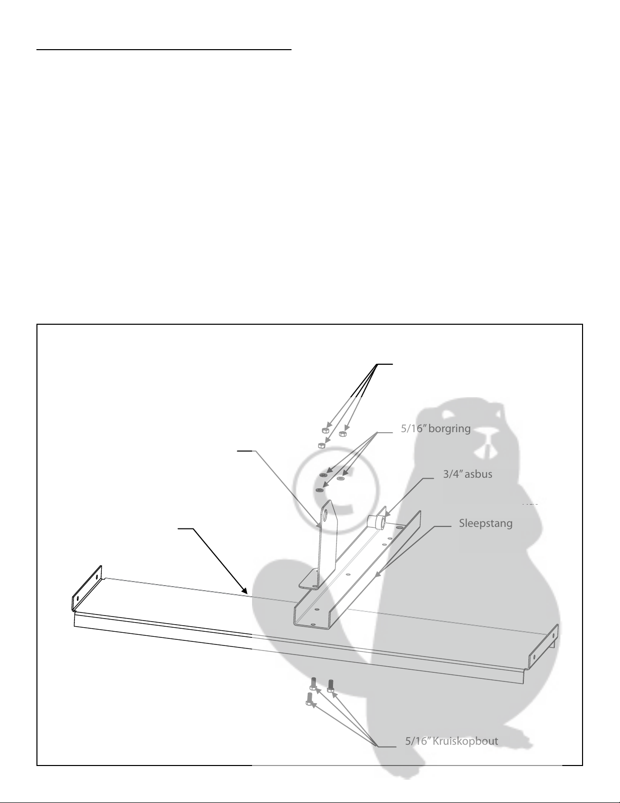
1. Plaats de basisplaat op een plat oppervlak, plaats een 5/16”x 3/4”kruiskopbout in het gaatje rechtsboven, plaats
de bout dan in het overeenkomstige gat van de sleepstang. Plaats een 5/16”borgring op de bout en maak het vast
met een 5/16” zeskantige moer. Bevestig nu de centrale plaat erop met de twee resterende gaatjes. Plaats 5/16” x
3/4”kruiskopbouten door de gaatjes in de basisplaat en de overeenkomstige gaatjes van de sleepstang en centrale
plaat. Plaats een 5/16”borgring op iedere bout en maak het vast met een 5/16”zeskantige moeren. Plaats een 3/4”
asbus in de centrale plaat. Zie afbeelding 1.
Figure 1
5/16” Hex Head Bolt
Base Plate
Center Plate
Tow Bar
3/4” Axle Bushing
5/16” Lock Washer
5/16” Hex Head Nut
5/16” x 2-1/4”
Hex Head Bolt
5/16” Nylock
Nut
Centrale plaat
Basisplaat
3/4”asbus
Sleepstang
5/16”Kruiskopbout
5/16”borgring
5/16”zeskantmoer
Afbeelding 1
4
Other manuals for TA500
1
Table of contents
Languages:
Other Precision Lawn And Garden Equipment manuals


