Precision TCT25FB User manual

~-J
-
Tread
pattem
or~
dre
may
vary
~a~ua~ Collitents
Safety Instructions
.2
Parts
.3
Assembly
Operation
Maintenance
Sprayer
Calibration..
Warranty
Co~ratL~Batüo~i~
on
your
purchase
of
a
new
4
7
Precision
Products,
mc.
Sprayer.
Your Sprayer
has
been engîneered and
built
to
give
you
the
most
dependable
and
best
performing
product
possible.
Proper
operation
and
maintenance will
12
ensure
long
satisfactory
service,
Please
study
the
manual
carefully
to
become
familiar
with
the
operation
and
maintenance
instructions.
Keep
your
manual
in
a
safe,
convenient
place
for
future
reference.
Always
mention the
model
and
part
number
in
any correspondence, when
ordering
parts.
1f
you
experience
any problem you
~ari
not
easily
resolve,
please
feel
free
to contact our
knowledgeable
and
helpful
customer
service
department
toll~free
at
1
(800)
225~~589L
Your
New
Spraver
Ceut~on~
Carefully
read
all
rules
and
instructions
for
safe
operation.
(Rev.
8/2017)
TJ[C~C[
~
The
foHowing
safe~’
orecautions
are
suggested.
This
Sprayer
is
designed,
engineered
and
tested
to
offer
reasonably safe
and
effective
service,
provided
that
It
is
operated
in
strict
accordance
with
:hese
ir~structions.
Failure
to
do
so
may
result
in
personal
injurq.
A~ways
obser~e
the
rules
of
safe
ope~ation.
Please
read
and
retain this
manuaL
o
Read
and
understand
your
tractor’s
owner’s
manual
and
towing
safety
rules,
know
how
to
operate
your
tractor
before
using
any
attachment,
o
Do
not
aHow
anyone
to
ride
or
sit
on
tow
behind
equipment
during
operation.
o
Be
alert for
holes
in
the terrain
and
other
hazards,
This
could
cause
you
to
lose
control
of
the
cart
and lawn
tractor.
Follow
maintenance
and
lubrication
instructions
as
outlined
in
this
manuaL
o
Tractor
braking
and
stability
may
be
affected with
the attachment
of
this
unit,
Be
aware
of
changing
conditions
on
slopes.
Refer
to
safety
rules
in
your
tractor
owner’s
manual
concerning
safe
operation
on slopes,
~t~iy
Cf~
stoep
~opes~
o
A!ways
operate
up
and
down
a
slope,
never
across
the
face
of
a
slopen
o
Do
not
drive
close
to
creeks, ditches or
public
highways.
o
Always
wear
substantia~
footwear,
Do
not wear
loose
fitting
clothing
that
may
get
caught
in
moving
parts.
o
Avoid
extremely sharp turns.
o
Foflow
the
maintenance instructions
as
outlined
in
this
owner’s
manual,
o
Do
not
exceed
maximum
towing
speed
of
4
M.P.H.
o
Wer~1finr~
of
den~er
of
~mproper
u~e
of
me
~prayer~
This
unit
is
intended
for
use
only
with
Riding Mowers
or
Garden
Tractors,
It
is
definitely
not
for
Highway
use,
being pulled
at
high
speeds,
or
transporting
passenger(s)
of
any
sort,
Such use
could
result
in
injuries
for
which
we
cannot
be
held
responsible.
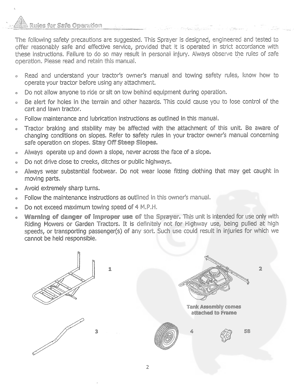
1
2
Tank
A~emb~y
comes
aft~ched
to
Fra~me
3
4
58
2

~l
—
(fl\
6
0
5
8
©©
15
18
20
Ref Part
~
Qty
Descr~pt~on
No~
1
5190TB
1
TCT
Frame
2
****
1
Tank
Assernbly
3
5191TB
2
TowBarTube
4
2029
2
Wheel
5
4289
1
Clevis
Pin
1/2”
x34/2”
1”
Head
6
4041
2
5/16”
x
2”
Hex
Head
Bolt
7
1248
2
5/16”
x
3/4”
Hex
Head
Bolt
8
2179 4
1/4”
x
3”
Hex Head
Bolt
9
1086
4
1/4”
x
2”
Hex
Head
Bolt
10
1817
12
1/4”
Flat
Washer
Ref
Part
~
Qty
Descr~ptbn
~
11
1044
2
5/16”
Flat
Washer
12
1276 4
5/16”LockWasher
13
1646
4
5/8”
Flat
Washer
14
5195
2
Cotter
Pin
1/8”
x
3/4”
15
1558
6
1/4”
Nylock
Nut
16
1275
4
5/16”
Hex
Head
Nut
17
1042
1
Hitch
Pin
Clip
18
3060
2
1”Tube
Plug
19
5153
1
5/16”Spacer
20
4265B
2
Clevis
Plate
58
2158
2
Control
Knob
3

(2)
1/2”
Wrenches
(1)
Pair
Needie
Nose
Phers
~
fr©~
~art©r~
Remove
aH
parts
and
hardware
packages
from the
carton.
Lay
out
aH
parts
and
hardware
and
identi~’
thern
using
the
Hiustrations
pages
2~3.
A~ernbr1y
îiip~
Loosely
tighten
aH
nuts
and
boits
at
fIrst,
Fully
tighten
when
the unit
is
completely
assembied.
1.
Place
the Tow
Bar
Tubes
under
the
front
of
T~T
Cart
Frame.
Take
four 1/4”
x
2”
Hex
Head
Boits,
place
a
1/4”
Flat Washer
on
each
bolt, insert
the
bolts
into
the
first
two
frame
holes
on
each
side.
insert
the
bolt through the
Frame
holes
and
through
the Tow
Bar
Tubes,
add one
more
1/4”
Flat
Washer
to
each
bolt
and
secure
with
1/4”
Nylock
Nuts.
Insert
1”
Tube
Plugs
into
front
holes
of
Tow
Bar
Tubes.
See
Figure
1.
TCTC~r~
Frame
1/4”
x
2”
~1ex
H~d
aollt
1/4”
F~t
W~her
1’T~b~Pbi~
Tow
B~r
1/4”
F~t
W~isher
F~L~re
1
1/4”
Nybck
NL~t
4

tw~i
~
:“
~
~
1
!~0
t/~’~
F~t
~J~’ashes,
two
±,~
~
r~U~
a~
~
5116”
Spacer.
Place
one
1/4”
x
3”
~
Head
Bolt
through
the
first
side
hole
in
Tow
Bar
Tubes theri
through the
second
tube.
Attach
a
l~4”
Flat
Washer
and
secure
with
a
1/4”
Nyiock NuL
Place
another
1/4”
x
3”
Hex Hea~
Bolt
and
insert
it
into
the
second
side
ho[e
on
the
Tow
Bar
Tnibe,
Piace
the
5/16”
Spacer
in
hetween
ife
two
Tow
Bar
Tube~
and
insert
the
bolt
through
the
5/16”
Space
and
through
th~
second
Tow
Bar
Tube.
Place
a
1/4”
Flat
Vfasher
onto the
bolt
and
secure
with
a
1/4”
Nylock
Nut.
See
Figure
2.
3.
Assemble
two
Clevis Piates,
two
5/16”
x
2”
Hex
Head
Bo[ts,
two
5/16”
Rat
Washers
two
5/16”
Nylock
Nuts,
one
1/2”
x
3-1/2”
Clevis
Pin
and
one
#14
Hitch
Pin
Cilp.
Insert
the
5/16”
x
2”
Hex
Head
Bolts
into
the
first
Clevis
Plates
on
one
each
side
over
the
first
bolt
on
the
Tow
Bar
Tube.
Then
insert
the
bolts
through
the
holes
in
the
second
Clevis
Plate,
place
one
5/16”
Flat
Washer
on
to
each
bolt
and
secure
with
a
5/16”
Hex
Head
Nut.
Place
the
1/2”
x
3-1/2”
Clevis
Pin
through
the
first
large
hole
in
the
Clevis
Plate
and
secure
with
the
#14
Hitch
Pin
Clip,
See
Figure
3.
~-
1/4”
x
3”
He~
H~d
L3©~t
5/16”
R~bber
~p~cer
Tow
8~B-
1/4”
~l~t
1/4»
F~t
f~~r
0
FigLwe
2
1/4”
Ny~ock
NL~t
Ck~v~Phi
~
C~evi~
Pb~te
5/16”
x
2”
Hex
He~id
Bout
u4
Tow
5~r
H~tch
Pi~
Ciip
5/16”
F~t
Wai~her
5/16”
Hex
He~d
H~t
5

4.
~1ssembie
the
~orn
~ng~e,
two
5/16”
x
3/4”
Hex
Head
3o~t,
a~o
5/16”
Lock
Wachers
and
two
He~.
:€tw
~ts.
:r~sa~t
~
5/11’
x
5/4”
cx
~j
1.e
F~
/:~cie
cr~.
:Le~
through
the T~T
Frame.
Attach
the 5/16”
Lcck Washers and
secui
e
with
5/16”
Hex
~ead
Nuts.
See
F~gure 4.
F~gjw’e
4
5.
Assembie
four
5/8”
Fiat
Washers,
two
Wheels
and
two
1/8”
x
3/4”
Cotter
Pins.
Piace
one
5/8”
Fiat
Washer onto
the
Axie
followed
by
a
Wheei,
and
another
5/8”
Fiat
Washer,
insert
a
1/8”
x
3/4”
Cotter
Pin
into
hole
in
the
Ade
and
spread
the
legs
of
the
Cotter
Pin
apart.
See
Figure
5.
!/~“
rxex
~e~d
~
L5oom
An~Be
TCT
Frame
Lock
W~~h~r
S/16”
~1ex
~1e~d
b~k~t
6

S~
F~ire
5
6.
Screw Pressure
Gauge
into
1/4”
Tee
w/port,
turning
in
a
clockwise manner,
See
Figure
6.
Pres~re
~aut~e
F~gLwe
6
7
t~
C~et~~~g
powc~
ooteined
uJm
a
i~
voit
Battery
5e
sure
to
conrect the
rad
to
the
positive
(+)
source
and
attach the black
to
the
negative(-)
source~
~~îPi~î~
B~fore
spraying chemic&s,
fiN
the
tank
full
of
plain
water
to
aflow famWarizotion
with
the
sprayer
and
to
prevent
the
waste
of
expensive
chernicals~
Tlli~e
~prayer
Iîiae
~aen~
c
~Mliy
d~c~e~
end
~
a~d
efto~d
p~dca
nieu~;
~are
~aO~eb~e
eer~oe
~f
pro~eniy
ca~d
fcr~
Wash
and
fiush
c~it
sp~aver
after
compledon
of
~
Fiush
when changing
chemicais
if
there
is
a
possibility
of
the
chernicals
being ~ncornpatiHe.
Use
of
a
detergent
is
advisable
if the
chemical
manufacture
does
not
make
s~ecific
cieaning
recom
mendations.
R
ush
system
corn
pietely,
inciuding
nozzies, Never
use
rnetal
objects
to
open
clogged
nozzles.
2.
Clean
sprayer
thoroughly
before
storing
at
the
end
of
the
spraying
season,
Permanent
type
anti
freeze
added
to
the
finat
rinse
wiN
leave
a
rust
inhibiting
film
on
parts
of the
sprayer~
o
Keeping
the
sprayer
clean and
dry
will
prolong
the
unit’s
life.
o
Grease
Wheels at
regular intervals,
at
east
once
every
six months,
more
frequently
if
used
regularly.
o
Should
rust
develop, sand
ightly
then
paint
area
with
enamel
paint.
o
Check
tire
pressure
at
regular
intervals,
Proper
infiation
will
prolong
the
life
of
tires
(see
side
of
tire
for
infiation
arnount).
Clieaiuik~
mid
Stora~je
Most
spray
materials
are
highly
corrosive, The
most
important
aspect of
long
dependable
service
from
your
sprayer
is
a
thorough
cleaning
immediately
to!
lowing
each
use.
In
addition,
the
residue
of
one
type of
chemical
could cause
an
undesirable
effect
when
a
different
chemical
is
used
for
a
different
purpose.
The most
effective
cleaning
method
is
to
pump
several
rinses
of
clean
water
through the
tank,
pump,
hoses,
boom,
spray
gun,
etc.
A
neutralizing
agent
such
as
a
solution
of
Nutra-Sol,
a
detergent
or
household
ammonia
as
recommended
by
the
chemical
manufacturer
can
assist
in
removal
of
a
persistent
chemicaL
When
the
system
is
thoroughly
cleaned,
drain the
tank,
suction
line,
pump,
hoses,
etc,
Parts
ariid
Support
Please
do
not
return
thisproduct
to
the
stom
prior
to
contactinp
Precision~
At
Precision
Products, mc,
our
goal
is
to
deliver
quality,
value
and
outstanding
service.
1f
for
any
reason
our
product
does
not
meet
your
expectations,
please
contact
us
and we
will
take
care
of
any
problem
you
may
have
with
this
unit.
When
ordering
replacement parts
please
have
the
model
number,
part
description,
part
number,
inspector
number
and
date
on
carton,
available
so
that
we
can
best
serie
you.
1
(SOO)
225~5691
www~prede~oriprod~r~cmcom
Pred~o~i
Producte
I~ic~
316
Lhiift
St0
L~nco~
XL
62656
8

Proper
calibration
is
one
of
the
most
important
parts
of
spraying.
Propery
cailbrated
sprayers
will
save
you
both
time
and
money.
How
to determine
the
gailcns
per
minute
(per
nozzie),
_____
~rW
~P~es
Per
Hio~r
4~ozz~e
epeckig
(b~
boom
spre~rh~g)
This
formule
is
useful
to
determine which
tip
to
use
on
your
boom,
especially
when
your
nozzie
spacing
is
different
from
the
standard
20”
or
40”
nozzle
spacing
on
Precision
Products, mc,
Sprayers~
For
example:
You
know
you
want
to
travel
3
MPH~,
apply
the
chemical
at
a
rate
of
20GPA~
The nozzle
spacing’s
are
33”
on
center.
By
using
the
formula
you
will
determine
how
many
gallons
per minute
(GPM)
per
tip
will
be
required
to
give
you
the
correct application.
Example:
20
GPA
x
3
MPH
=
60
x
33”
(nozzle
spacing)
=
1980
divided
by 5940
+
.333
GPM
You
have
now
determined
that
you
need
a
tip
with
GPM
of
.333.
Find
the
type
of
tip
you
want
to
use. For
example,
an 80
degree
flat
fan
spray
tip
and
then
determine
what
pressure
you
plan
to
spray
aL
Let’s say
30
PSL How
do
you
check
this
calibration?
By
using
this
formula.
~PA
5940
x
~
(Per
Nozz~e)
MPHxW
Multiply
5940 x
.333
GPM
+
1783.8.
Multiply
3
MPH
x
33
(nozzle
spacing)
=
99.
Divide 1783.8
by
99
=
18.06
gallons
per acre.
13y
simply adjusting
your
pressure
or
your tractor
speed, you
will
obtain
the
20
GPA
rate,
The
second
formula
is
used
to
determine whether
an
old
tip
(one
on
which
you
cannot
identify
the
number)
is
still
spraying the right
amount
of
chemicals.
You can
determine
how
many
GPM
a
tip
is
spraying,
with
the
use
of
a
catch
jar
and
stop
watch.
Hold
the
jar
under
the
tip
so
you
catch
the total
spray
for
one
minute.
The
amount
in
the
jar
indicates
the
GPM.
Calibrate
your
sprayer
carefully.
1f
your
tips
are
worn,
replace
them,
New
tips
are
a
fraction
of
the
cost
of
using
either
too
much
or
too
little
chemicals,
Also,
you
can
use
these formulas
to
help
determine
if
the
intended pump
has
the
volume capacity
to
meet
your
spraying
rieeds.
0

t’
0
0%
/
0%

3
3£
~
/_
F
2%
53
28
25
25
‘55
TCT
Fr~rne
Asee~ib~y ~how~i
p~gee
2~5
Ref
Part
P~o~
Qty~
Dcr~ption
No~
1
5190TB
1
TCT
Frame
2
1
Tank
Assembly
3
5191TB
2
TowBarTube
4
2029
2
Wheel
5
4289
1
Clevis
Pin
1/2”
x3-1/2”
1”
Head
6
4041
2
5/16”
x
2”
Hex
Head
Bolt
7
1248
6
5/16”
x
3/4”
Hex
Head
Bolt
8
2179
2
1/4”
x
3”
Hex
Head
Bolt
9
1086 4
1/4”
x
2”
Hex
Head
Bolt
10
1817
12
1/4”
Flat
Washer
11
1044
6
5/16”
Flat
Washer
12
1276
10
5/16”LockWasher
13
1646
4
5/8”
Flat
Washer
14
5195
2
Cotter
Pin
1/8”x
3/4”
15
1558
6
1/4”
Nylock Nut
16
1275
4
5/16”
Hex Head
Nut
17
1042
1
Hitch
Pin
Clip
18
3060
2
1”Tube
Plug
19
5153
1
5/16”Spacer
20
4265B
2
Clevis
Plate
21
3632
10
Hose
Clamp
(Stainless
Steel)
22
3604
4
10-24 x
1-1/4”
Round
Head
Screw
23
3605
4
#10
Flat
Washer
24
3636
6
#10
Lock
Washer
25
3780
1
Wire
Harness
26
3626
1
25
Gallon
Sprayer Tank
27
3784
2
Wand Holder
28
3620
3
NozzieCap
Ref
Part
Ma.
Qty~
De~criptio~
Mo~
29
3619
3
Suction
Strainer
30
3777
1
3/8”
Rubber
Hose
24”
31
3607
1
Hose
Barb
3/8”
32
3613
2
10-24
x
1/2”
Bolt
33
3601
1
Tank
Lid
34
3609
1
Electric
Pump
Motor
(L8
W/Switch)
35
3728
1
3/8”MPT
x
1/4”MPT
Nipple
36
3688
1
Nylon
Tee,
1/4”
w/port
37
3731
1
1/4”MPTx3/8”HB
38
3773
1
3/8”
Rubber
Hose
15’
39
3658
1
Sprayer
Wand
&
Nozzle
40 3730
1
1/4”
MPT
x
1/4”
FPT
Valve
41
3729
1
1/4”
MPT
x
1/2”
HB
Hose
Barb
42
3775
1
1/2”
Clear
Hose
40”
43
3723
1
Nylon
Tee,
1/2”
44 3776
2
1/2”
Clear
Hose
19-1/2”
45
3725
2
11/16”MPSx1/2”HBELBHBw/nut
46
3719
2
Nozzle
2~5”
Blue
47 4881TB
1
Boom
Arm Assembly
48
3733
1
Drain
Cap
w/Washer
49
3659
1
11/16”MPTx3/8”HB
50
3639
1
Grommet
5/8”
l-LD.
x
3/8”
(Thick)
51
3687
1
Pressure
Gauge
52
4879TB
1
Boom
Arm
Assembly
RH
53
4880TB
1
Boom
Arm
Assembly
LH
54
2158
2
Control
Knob
55
2172
2
5/16”
Fender
Washer
55
£2
1
45
33
30
2%
49
29
34
P’ot
eS
pertc
ehow~
22
11

—~
~
~jj~t~j~
t1
~
~~Yft
7
~?
~
~i
~:~tf
~
[
~_j
~---,~
~_‘LJ
J
~-
The
Fimited
warranty
set
forth
below
is
given by Precision
Products,
Incorporated
with
respect
to
new
mercha:~dise
p~rchesed
end used
in
the
United
States,
its
~ossessions
and
territories~
Precision
Products,
Incorporeted
warranties
the
product
(s)
listed
against
defects
in
materia!
and
workmanship,
and
will
at
our
option,
repair
or
replace,
free
of
charge,
any
part
found
to
be
detective
in
materials
or
workrnanship.
This
limited
warranty
shail
only
apply
if
this
product
has
been
assembled,
operated,
and
maintained
in
accordance
with the
owner’s manual
furnished
with
the
product,
and
has
not
been
subject to
misuse,
abuse,
neglect,
accident,
improper
maintenance,
alteration,
vandalism,
theft,
fire,
water,
or
damage
because
of
other
peru
or
natural
disaster.
Normal wear
parts
or
components
thereof
are
subject
to
separate
terms
as
follows:
All
normal
wear
parts
or
component
failures
will
be
covered
on
the
product
for
a
period
of
one
year.
Parts
found
to
be
detective
within
the
warranty
period
will
be
replaced
at
our expense.
Our
obligation
under
this
warranty
is
expressly
limited
to
the
replacement
or
repah.
at
our
option,
of
parts
found
to
be
defective
in
materia!
and
workrnanship.
Co~itacth~ Service
Warranty
parts replacements
are
available,
only
with
Proof
of
Pwthese,
through
our Customer
Service
Department
Cail
1
(SEDO)
225~5891
This limited
warranty
does
not
provide
coverage
in
the
following
cases:
1.
Routine
maintenance
items
such
as
lubricants
and
filters.
2.
Normal
deterioration
of
the
exterior
finish
due
to
use
or
exposure.
3.
Transportation
and/or
labor charges.
No
implied
warranty,
inciuding
any
implied
warranty of
merchantability
of
fitness
for
a
particular
purpose,
applies
after
the
applicable
period
of
express
written warranty
above
as
to
the
part
as
identified
below.
No
other
express
warranty
whether written
or
oral,
except
as
mentioned
above,
given
by
any
person
or
entity,
including
a
dealer
or
retailet~
with
respect
to
any
product,
shail
bind
Precision Products,
mc.
During
the
period
of
the
warranty,
the
exclusive
remedy
is
repair
or
replacement
of
the
product
as
set
forth
above.
The
provisions
as
set
forth
in
this
warranty
provide
the
sole
and
exclusive remedy
arising
from
the
sale.
Precision
Products,
Inc.
,
will
not
be liable
for
incidental
or
consequentie!
loss
or
damage
including,
wit~out
lirnitation,
expenses
incurred
for
substitute
or
replacement
lawn
care
services
or
for
rental
expenses
to
temporarily
repiace
a
warranted
product.
Sorne
states
do
not
allow
the
exclusion
or
limitation
of
incidental or
consequential
damages, or
limitations
on
how
long
an
implied warranty
asts,
so
the
above
cxci
usions
or lirnitations
may
not
appiy
to
you.
During
the
warranty
period,
the
exclusive
remedy
is
replacement
of
the
part.
In
no
event
shall
recovery
of
any
kind
be
greater
that
the
amount
of
the purchase
price
of
the
product
sold.
Alteration of
safety
features of
the
product
shali
void
this
warranty.
You
assume
the
risk
and
liabulity
for
loss,
darnage,
or
injury
to
you
and
your
property
and/or
to
others
and
their
property
arising
out
of
the
misuse
or
inability
to
use
this
product.
This
limited
warranty
shall
not
extend
to
anyone
other
than
the
original purchaser or
to
the
person
for
whom
it
was
purchased
as
a
gift.
Local
Laiw
to
thie
Werrer~ty
This
limited
warranty
gives
you
specific
legal
rights,
and
you may
also
have
other
rights which
vary
from
state
to
state.
Werranty
Period
The
Warranty
period stated
below
begins
with
the
Proof
of
Pe.irchese.
Without
the
proof
of
purchase,
the
Warranty
period
begins
from the
date
of
manufacture.
Sprayer
Werrenty
Period
The
warranty
period
for
this
unit
is
as
follows:
All
parts
are
covered
one
year from
date
of
sale.
12

1
~
7
~S~—
-
—
/
j
r
Fj_~
/~
L~
“~
~J
X~~2
d
~F~Lr~~)I
~
~~-I___
-2
rui
n~uu~
ii
—-
~~tret~en-8
Tableau
d~application
Pièces
12
Garantie
Fédtet~o~is
pour
votre
achat.
Votre
.47
produit
a
été
spécialement
conçu
pour
vous
offrir
le
produit
le
plus
fiable
et
le
plus
perforrnant
possible.
Si
vous
rencontrez
un
problème
que
vous
ne
pouvez
pas
résoudre, n’hésitez
pas
~
contacter
notre
service
dient compétent
et
seniiable
sans
frais
au 1
(800)
225-5891.
Awertdsse~nent;
Lïsez
prudemment
les
règles
et
instructions
pour
un
fonctionnement
en
toute
sécurité.
Veuillez
conserver
ce
~
L
Crnî~tern~
dL~
~narn~el
Sécurité
Instructions
Assemblage
Eurogarden
/~
~ges
de
sécud~
Nous
vous
conseilloris
de
suivre
les
règ!es
de
sécur~té
suivantes.
~e
Puivérisa~eu~
a
été
conçu,
~ssemblé
et
testé
afin
d’assurer
une
utilisation
en
toute
sécurité,
~
condition
de
respecter
scrupuleusement
les
consignes
stipulées.
Un
non~respect
des
consignes
peut
entrainer
des
lésions
corporelles.
Veillez
~
toujours
respecter
les
consignes
de
sécurité
lors
de
i’utilisation
de
‘appareil.
Veuillez
lire
et
conse~er
ce
man
uel.
Veufliez
lire
et cornprendre
le
manuel
d’utilisation
de
votre
tracteur
ainsi
que
les
règles
~
respecter
lors
du
rernorquage.
Veuillez
apprendre
~
faire
fonctionnervotre
tracteur
avant
d’utiliser
un
quelconque
accessoire.
o
Veuillez
veiller
~
ce
que
personne
ne
monte
ou
ne
s’assied
dans
iC
remorque
arrière
lors
de
I’utHisation
de
l’appareH.
o
Veuillez
faire
attention
aux
trous
dans
le
terrain
et
autres
désagrémeots.
Cda
peut
vous
faire
perdre
le
contrôle
de
la
remorque
et
du
tracteur
de
pelouse.
o
Veuillez respecter
es
consignes
d’entretien
et
de
lubrification
stipulées
dans
ce
manuel,
o
Cet
appareil
peut
affecter
Ie
freinage
et
la
stabilité
du
tracteur.
Veuillez
faire
attention
â
l’inclinaison
des
pentes.
~uiter
les
pentes
abruptes~
o
Veuil!ez
rouler
en
montée
et
en
descente
tout
en
suivant
la
pente
et
ne
jamais
la
traverser
~
diagonale.
o
Veuillez
éviter
de
rouler
~
proximité
de
ruisseaux,
fossés
ou
de
le
voie
publique.
o
Veuillez
veiller
~
toujours
porter
des
chaussures
adaptées.
Veuillez
éviter
de
porter
des
vêtements
amples
susceptibles
de
se
coincer
dans
les
lames
de
!‘appareil.
°
Veuillez
éviter
les
virages
brusques.
o
Veuillez
suivre
les
consignes
d’entretien
stipulées
dans
Ie
manuel
d’utilisation.
o
La
vitesse
de
remorquage
ne
doit
pas
dépasser
6km/h.
Attention
au
danger
dérivarit
d’une
mauvaise
utilisation
du
Pulvérisateur.
Cet
appareil
est
uniquement
compatible
avec
les
tondeuses
~
gazon
et
les
tracteurs
de
pelouse.
II
est
strictement
déconseillé
de
l’utiliser
sur
le
route,
afin
d’être
remorqué
~
haute
vitesse
ou
de
transporter
des
passagers. Nous
ne
somnmes
pas
responsables
de
toute
blessure
causée
per
une
mauvaise
utilisatiori
de
cet appareil.
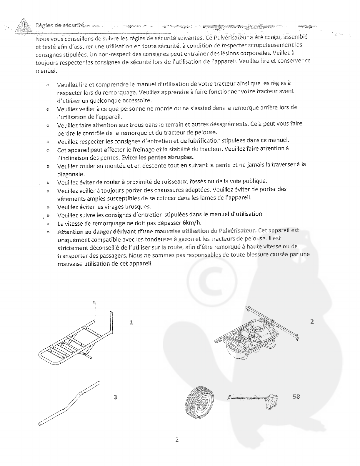
1
2
3
~
58
2

19
20
~—
~I
~
~
•9
—
11.
12
8
13
5
14
15
16
~1o~
Qté~
~esr~pt~on
Réf
P~èce
1
3
4
5
7
8
9
10
5190GY
5191GY
2029
4289
4041
1248
2179
1086
1817
1
1
2.
2
1
2
2
4
4
12
No. No.
QtéJ
Descript~on
Rét
P~èce
Châssis
TCT
Réservoi
r
Tube
de
la
barre d’atte{age
Roue
Axe
de
chape
1,3
x
8,9cm
—
tête
de
5cm
Boulon hexaçjonat
0,8
x
5cm
Boulon
hexagonal
0,8
x
1,9cm
Boulon
hexagonal
0,6
x
7,6cm
Boulon
hexagona)
0,6
x
5cm
RondeHe
plate
0,6cm
11
12
13
14
15
16
17
18
19
20
21
1044
1276
1646
5195
1558
1275
1042
3060
5153
4265G
2158
2
4
4
2
6
4
1
2
1
2
2
Rondelle plate
0,8cm
Rondelle
frein
0,8cm
Rondelle
plate
1,6cm
Goupille
fendue
0,3
x
1,9cm
Ecrou
Nylock 0,6cm
~crou
hexagonai
0,8cm
GoupWe
Embout
du
tube
2,5cm
Entreto~se
0,8cm
Chape
Bouton
de
commande
3

cflt~Ee
re~Ln~a
pti~r
5e
cliawttag~a
d~
c5~ar5ot
(2)
1/2”
Clés
d’1,3crn
(1)
P~nce
~
becs
fins
5e
cartoc~
Retirez
et
disposez
toutes
es
plèces
et
équipements
du
carton,
identifiezies
~
partir
des
illustrations
en
page
2
et
3.
Conseil de
mon5~age~
serrez
les
écrous
et
boulons
grossièrement.
Serrez-les
â
fond
une
fois
que
‘appareil
est
totalement
monté.
1.
Placez les
tubes
de
la
barre
d’attelage
sous
le
châssis
du
chariot
TCY.
Prenez
quatre
boulons
hexagonaux
de
0,6
x
5cm.
Placez
une
rondelle
plate
de
0,6cm
sur
chaque
boulon,
insérez
les
boulons
dans
les
deux
premiers
trous
de
chaque
cote
du
châssis.
Insérez
le
boulon dans
les
trous
du
châssis
et
dans
les
tubes
de
la
barre
d’attelage, ajoutez
une
rondelle
plate
de
0,6cm
sur
chaque
boulon
et
sécurisez
avec
des
écrous
Nylock
de
0,6cm.
lnsérez
les
embouts
des
tubes
sur
les
trous avant
des
tubes
de
la
barre
d’attelage.
Voir
schéma
1.
f
Boubn
hexa~o~a~
0,6
x
5cm
RondeNe
p~ate
0,6cm
Châs~s
char~ot
TCT
Tube barre
d’afte~age
RondeNe
pbte
0,6cm
Sdiéma
1
Ecrou
~Uy~ock
0,6cm
4

2.
Assembiez
deux
bou~ons
xan~u~
ce
0,6
x 7,6cm,
deux
rondei~es
ptates
de
0,6
cm, deux
écrous
Nylock
de
0,6cm
et
une
entretoise
o~
0,8cm.
Placez
un
bou~on
hexagonal
0e 0,o x
7,~
cm
dans
te
premier
trou
latérat
des
tubes
de
la
barre
d’attelage,
puis
dans
te
second
tube. Attachez
une
rondelle
plate
de
0,6cm
et
sécurisez
avec
un
écrou
Nytock
de
0,6cm.
Placez
un
autre
boulon
hexagonat
de
0,6
x
7,6cm
et
insérez-te
dans
le
second
trou
tatéral
du
tube
de
la
barre
d’attelage.
Placez
une
eritretoise
de
0,8cm
entre
les
deux
tubes
de
la
barre d’attelage
et
insérez
un
bouton
dans
t’espace
de
0,8cm
et
dans
le
second
tube
de
la
barre
d’attelage.
Piacez
une
rondeHe
plate
de
0,6cm
sur
le
boulon
et
sécurisez~la
avec
un
écrou
Nylock
de
0,6cm.
Voir
schérna
2.
3.
Assemblez
les
deux
chapes,
deux
boulons
hexagonaux
de
0,8
x
5cm, deux
rondelles
plates de
0,8cm,
deux
écrous
Nylock
de
0,8cm,
un
axe de
chape
d’1,3
x
8,9
cm
et
une
goupiNe
#14.
Insérez
les
boulons
hexagonaux
de
0,8
x
5cm
des
deux cotes
de
ta
première
chape
sur
le
premier
boulon
du
tube
de
la
barre d’attelage.
Puis
insérez
les
boulons
dans
les
trous
de
la
seconde
chape,
placez
une
rondelle
plate
de
0,8cm
sur
chaque boulon
et
sécurisez
avec un
écrou
hexagonal
de
0,8cm.
Placez
l’axe
de
chape
d’1,3
x
8,9cm
dans
le
premier
grand
trou
de
la
chape
et sécurisez
avec
Fa
goupille
#14.
Voir
schéma
3
t
0
rr~
B~ar~
hexa~ora~
0,6
x7,Scm
Barre
d’
Schéeia
2
5/16”
Rubber
Spa
0
RondeHe
p~ate
0,6cm
Ecrcu
Ny~ock
0,6cm
Axe
de
chape
Chape
~/f’
Bou~on
hexagonail
0,8
x
5cm
Barre
d’attebge
GoupU~e
RondeHe
pDate
0,8cm
5
Ecrou
hexagonat
0,8cm
5

~l,
/~ssem~b{e:
ic
c~’~re
ce
la
Ian~
~cux
bo~V
hex~cocau~~,8
i,~cn.
~ix
ro~idci~
~rein
de
0,8cm
et
deux
boulons
hexagonaux 0,8cm.
Insérez
ie
boulon hexagonal de
0,8
X
lr9Cm
dans
le
cadre
de
la
lance
et ensuite
dans
le
châssis
TJF.
Fixez
les
rondelles
frein
de
0,8cm
et
sécurisez
avec
les
écrous
hexagonaux
de
0,8cm.
Voir
schéma
4.
5.
Assemblez
quatre
rondelles
plates
1,6cm,
deux
roues
et
deux goupilles
fendues
0,3
x
1,9cm.
Une
rondelle
plate
d’1,6cm
sur
Î’essieu
puis
une
roue
et
une
autre
rondelle
plate
d’1,6cm.
Jnsérez
une
goupi~e
fendue
de
0,3
x
1,9cm
dans
le
trou
de
I’essieu
et
séparez
les
jambes
de
la
goupille
fendue.
Voir
schéma
5.
6

6.
Vissez
~e
manomètre
sur
te
support
T
de 0,6cm
en
tournant
dans
te
sens des
atguilJes
d’une
montre. Voir
schéma
6.
Ron
de~
~e
pbte
1,6cm
GonpHDe
fendue
0,3
x
1,9cm
Manomètre
Schéma
6
7
7

Nettoyer
et
purgez
Ie
pulvéris~Ur
~
Le
cou~dnt
d’a~Iî~eLaLon
est
obtenu
depuis
une
batterie
de
12
volts.
Soyez
sur
de
brancher
le
câble
rouge
sur
la
borne
positive
(+)
et
de
brancher
Ie
câble noir
sur
la
borne
riégative
(-).
Conse~s
d’eutret~en
pulvériser
des
produits
réservoir
«eau
pour
avec
le
pulvérïsateur et
des
produits
chimiques
Ce
peDvér~s~teur
a
été
e~t~èrernerDt
cortçu
et
fabriqué
pour
vou~s
serv~r
faib~ement
perid~oit
de
~or~gue~
anriées,
~
est
carrectement
entretenu~
Conserver
votre
pulvérisateur
propre
et
sec
prolongera
sa
durée
de
vie.
Graissez
les
roues
de
manière
régulière,
au
moins une fois
tous
les
six
mais,
plus
souvent
si
vous
l’utilisez
fréquemment.
o
Si
de
la
rouille
venait
~
se
développer,
sablez
légèrement
la
zone
rouillée
et appliquez
une
couche
de
vernis.
Vfrifi~z
la
pression. des
ppeus
de
manière
reg~.,jliere.
~Jne
infiation
adaptee
prolonger~
la
duree
de vie,des
pfleus
(reqardez
sur
le
cate
du
pneu
pour
verrfler
l’inflation).
~ettoyage
et
rangement
La
plupart
des
composants
présents
dans
les
sprays
sont hautement
corrosifs.
La
clé
de
la
longue
vie
de
votre
pulvérisateur
est
un
nettoyage
complet
immédiatement
après
chaque
utilisation.
De
plus,
un
type
de
résidu
chimique peut
causer
des
effets
indésirables
lorsque
vous utilisez
un
autre
type
de
produit
chimique
pour
un
différent
objedif.
La
méthode
de
nettoyage
La
pLus
efficace
est
de
purger
plusieurs
fois
â
l’eau claire
le
réservoir,
La
pompe,
les
tuyaux,
La
lance,
le
pistolet
pulvérisateur,
etc.
Un
agent
neutralisant
te!
qu’une
solution
Nutra-Sol,
un
détergent
ou
un
ammoniac ménage’,
r~cc~~a’~dé
par
le
fabricant
de produits chimiques, peuvent vous aider
~
éliminer
les
produits
chimiques
tenaces.
Lorsque
le
système
est
entièrement
nettoyé,
videz
le
réservoir,
le
tuyau
d’aspiration,
la
pompe,
les
tuyaux, etc.
réaisé
c[aque
Jape
de
v~Lr~
prog:~amme,
Purgez
Ie
pulvérisateur
lorsque
vous
changez
les
produits chimiques,
s9I
existe
un
risque
d’incompatibilité
de
produits.
Utilisez
un
produit
détergent,
si
Ie
fabricant
de
produits
chimiques
ne
recommande
pas de
nettoyage
spécifique,
Purgez
Ie
système
entièrement, y compris
les
embouts,
Ne
jamais
utiliser
d’objets
métalliques
pour
déboucher
les
embouts
obstrués.
2.
Nettoyez
entièrement
Ie
pulvérisateur
avant
de
Ie
ranger
en
fin
de
saison,
L’ajout
dTun
antigel
permanent
lors
du
rinçage
final
laissera
une
couche
inhibitrice
de
rouille
sur
les
pièces
du
pulvérisateur.
o
P~èces
et
ass~stance
,4~
Veu~llez
ne
pas
retourner
ce
produ~t
en
magashi
avant
dtavofr
contacté
“~“
Precis~on.
A
Precision
Products
mc.,
notre
but
est
de
fournir
des
services
de
qualité,
de
valeur et
d’excellence.
Si
pour
quelle
raison
que
ce
soit,
notre
produit
ne
satisferait
pas vos
attentes,
veuillez
nous
contacter
afin
que
nous
traitions
tout
problème
lié
~
cet
appareil.
Lorsque vous
commander
des
pièces
de
rechange,
veuiilez
vous
munir
du
numéro
de
modèle,
de
la
description
de
la
pièce,
du
numéro
de
la
pièce,
du
numéro
d’inspection
et
de
la
date
figurant
sur
le
carton,
afin
que
nous
puissions
mieux
vous
assister.
1
(800)
225~5891
www.precisionprodhic.com
Preds~on
Products
mc.
316
Liruft
St.
Lhicohi
IL
62656
P~CfLfl~
Avant
de
chimiques,
remplissez
Ie
permettre
Ia
familiarisation
pour
empêcher
de
gâcher
couteux.
8
Table of contents
Languages:


