manuals.online logo
Brands
  1. Home
  2. •
  3. Brands
  4. •
  5. Toro
  6. •
  7. Paint Sprayer
  8. •
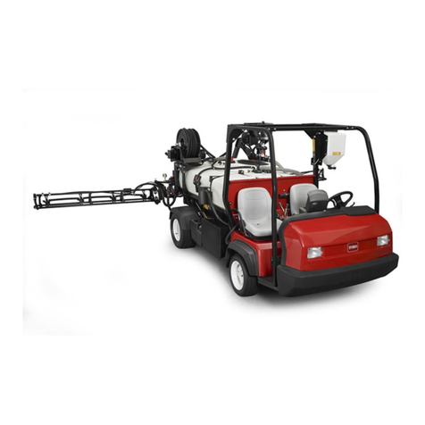
  9. Toro 125-8120 User manual

Toro 125-8120 User manual

Other Toro Paint Sprayer manuals

Toro 41086 User manual

Toro

Toro 41086 User manual

Toro 41229 User manual

Toro

Toro 41229 User manual

Toro MULTI-PRO 1100 User manual

Toro

Toro MULTI-PRO 1100 User manual

Toro Multi-Pro 5800 User manual

Toro

Toro Multi-Pro 5800 User manual

Toro Multi Pro 41602 User manual

Toro

Toro Multi Pro 41602 User manual

Toro 41440 Specifications

Toro

Toro 41440 Specifications

Toro 34215 User manual

Toro

Toro 34215 User manual

Toro 34230 User manual

Toro

Toro 34230 User manual

Toro Multi Pro 5800-D User manual

Toro

Toro Multi Pro 5800-D User manual

Toro 41107 User manual

Toro

Toro 41107 User manual

Toro Multi Pro WM 41240 User manual

Toro

Toro Multi Pro WM 41240 User manual

Toro Multi Pro 5800 User manual

Toro

Toro Multi Pro 5800 User manual

Toro 41594 User manual

Toro

Toro 41594 User manual

Toro Spray Master 34235 Manual

Toro

Toro Spray Master 34235 Manual

Toro 41188 User manual

Toro

Toro 41188 User manual

Toro Multi Pro 5800-D User manual

Toro

Toro Multi Pro 5800-D User manual

Toro GeoLink 41624 User manual

Toro

Toro GeoLink 41624 User manual

Toro 41394 User manual

Toro

Toro 41394 User manual

Toro 41198 Multi-Pro 1250 User manual

Toro

Toro 41198 Multi-Pro 1250 User manual

Toro 41177 Multi-Pro 1250 User manual

Toro

Toro 41177 Multi-Pro 1250 User manual

Toro Multi Pro 1750 User manual

Toro

Toro Multi Pro 1750 User manual

Toro Multi Pro 5800-D User manual

Toro

Toro Multi Pro 5800-D User manual
Toro 41564 User manual

Toro

Toro 41564 User manual

Toro Multi Pro 5800 User manual

Toro

Toro Multi Pro 5800 User manual

Popular Paint Sprayer manuals by other brands

Idex Akron Brass FS100 quick start guide

Idex

Idex Akron Brass FS100 quick start guide

mbp TEL 15BS instructions

mbp

mbp TEL 15BS instructions

Solo 425 Classic Original instructions

Solo

Solo 425 Classic Original instructions

WAGNER AirCoat GM 4100 AC operating manual

WAGNER

WAGNER AirCoat GM 4100 AC operating manual

Graco 1095 HI Operation manual

Graco

Graco 1095 HI Operation manual

Titan MultiFinish 440 owner's manual

Titan

Titan MultiFinish 440 owner's manual

Graco GUSMER D Series instructions

Graco

Graco GUSMER D Series instructions

SNOWJOE Sunjoe 24V-GS-LTW-RM Operator's manual

SNOWJOE

SNOWJOE Sunjoe 24V-GS-LTW-RM Operator's manual

Walther FSP-01 Assembly instructions

Walther

Walther FSP-01 Assembly instructions

Fimco LG-4-3-1 owner's manual

Fimco

Fimco LG-4-3-1 owner's manual

Nordson MicroMax 2 manual

Nordson

Nordson MicroMax 2 manual

Bonide 051 Operation and service instructions

Bonide

Bonide 051 Operation and service instructions

zogics Z-DAS instruction manual

zogics

zogics Z-DAS instruction manual

KISANKRAFT KK-KBS-165 Operation manual

KISANKRAFT

KISANKRAFT KK-KBS-165 Operation manual

Matrix SG 650 Translation of the original instructions

Matrix

Matrix SG 650 Translation of the original instructions

paasche VV Instructions and parts list

paasche

paasche VV Instructions and parts list

Carlisle DeVilbiss JGA-510 Service manual

Carlisle

Carlisle DeVilbiss JGA-510 Service manual
Gardena 11120 Operator's manual

Gardena

Gardena 11120 Operator's manual

manuals.online logo
manuals.online logoBrands
  • About & Mission
  • Contact us
  • Privacy Policy
  • Terms and Conditions

Copyright 2025 Manuals.Online. All Rights Reserved.

FormNo.3378-936RevA
FinishingKit
FoamMarkerforMultiPro1750TurfSprayer
ModelNo.125-8120
InstallationInstructions
Note:TheFoamMarkerKitisrequiredfortheinstallation
ofthisproduct.ContactyourAuthorizedToroDealerfor
moreinformation.
WARNING
CALIFORNIA
Proposition65Warning
Thisproductcontainsachemicalorchemicals
knowntotheStateofCaliforniatocausecancer,
birthdefects,orreproductiveharm.
Safety
Note:Determinetheleftandrightsidesofthemachine
fromthenormaloperatingposition.
SafetyandInstructional
Decals
Safetydecalsandinstructionsareeasily
visibletotheoperatorandarelocatednear
anyareaofpotentialdanger.Replaceany
decalthatisdamagedorlost.
125–8112
1.Rightboom3.Leftboom
2.Bothbooms
Installation
LooseParts
Usethechartbelowtoverifythatallpartshavebeenshipped.
ProcedureDescriptionQty.Use
Foam-markerbracket1
Carriagebolt1
U-bolt1
Flangenuts(3/8inch)3
Spacer1
1
R-clamp1
Installthenishingkitbracket.
©2013—TheToro®Company
8111LyndaleAvenueSouth
Bloomington,MN55420
Registeratwww.T oro.com.OriginalInstructions(EN)
PrintedintheUSA
AllRightsReserved*3378-936*A
ProcedureDescriptionQty.Use
Foammarker(soldseparately)1
Bolts4
2Nuts(1/4inch)4
Attachthefoammarker(sold
separately).
Wiringharness
Switchbracket1
Rockerswitch1
Paddleswitch1
3
Bolts4
Installtheswitchesandroutethewire
harness.
1
InstallingtheFinishing-kit
Bracket
Partsneededforthisprocedure:
1Foam-markerbracket
1Carriagebolt
1U-bolt
3Flangenuts(3/8inch)
1Spacer
1R-clamp
Procedure
1.Loosentheboltonthetopofthestrap(Figure1).
1
23
4
g017xxx
5
Figure1
1.R-Clamp4.Strapbolt
2.Spacer5.U-Bolt
3.Carriagebolt
2.Placethecarriageboltthroughthestrapofthesprayer
tankbelt(Figure1).
3.Slidethespacerontotheboltandplacethebracket
ontotheboltasshowninFigure1.
4.PlacetheR-clampontotheboltandsecurethebolt
withaangenut(3/8inch).
5.PlacetheU-boltontothemachineasshowninFigure
1.
6.PlacethebracketontotheU-boltandsecurewiththe
2angenuts(3/8inch).
2
AttachingtheFoamMarker
(SoldSeparately)
Partsneededforthisprocedure:
1Foammarker(soldseparately)
4Bolts
4Nuts(1/4inch)
Procedure
Securethefoammarkertothebracketusingthe4boltsand
4nutsasshowninFigure2.
g023693
Figure2
2
3
InstallingtheSwitchesand
RoutingtheWiringHarness
Partsneededforthisprocedure:
Wiringharness
1Switchbracket
1Rockerswitch
1Paddleswitch
4Bolts
InstallingtheSwitches
1.Installthepaddleswitchontotheswitchbracket.
2.Removethesteeringwheelcoverplate,removethe
steeringwheelhardware,andpullthesteeringwheel
offthecolumn(Figure3).
1
2
3
4
g023699
Figure3
1.Steeringwheelcoverplate3.Paddleswitchonthe
switchbracket
2.Steeringwheelhardware4.Bolts
3.Slidetheswitchbracketontothesteeringwheel
column,andsecurethebracketwiththe4bolts(Figure
3).
4.Installthesteeringwheel.
5.Removethe4boltsontheswitchpanel,andliftup
thecoverplate.
6.Installtheon/offswitchasshowninFigure4.
g023899
1
Figure4
7.Securethecoverplate.
RoutingtheWiringHarness
Note:Lifttheseattoroutethewireharness.
RoutethewireharnessasshowninFigure5andFigure6.
g023694
Figure5
3
g023902
Figure6
Operation
UsingtheControls
Foampaddleswitch—activatesthecompressor,generating
aowoffoamandairtotherightorleftboomsection
(Figure3).
Foamon/offswitch—activatesthecompressor,generating
aowoffoamtobothoftheboomsectionssimultaneously
(Figure4).
Indicatormarkings—locatedonthesideofthetank;they
indicatethesolutionlevelinthetank.
Foamregulatoradjustmentvalve—controlsthe
consistencyofthefoamsolution.Adjustingthevalvecontrols
theamountofsoapsolutiondeliveredtothefoamnozzles.
Increasingtheowresultsinlarger,morefrequentfoam
drops;decreasingtheowresultsinsmaller,lessfrequent
foamdrops(Figure7).
Note:Awaterymarkerconsistencymaybehelpfulonwindy
days.
Pressurereliefvalve—pulltheredtabonthetankcap
outwardtorelievepressureinthetank(Figure7).
FillingtheTankandAdjusting
theFoamDensity
Important:Flushthesystemwithcleanwaterafter
eachuse,especiallyafterusinghardwater.Donotapply
lubricatingoils,grease,orotherpetroleumproductsto
thecompressormotorassembly.
1.Ensurethatboththeleftandrightboomswitches
locatedontheconsoleareintheOffposition.
2.Pulloutontheredpressurerelieftab,andremovethe
blackcapfromthetank.
3.Pourtheproperamountwaterintothetank,andthen
addfoamconcentratethroughtheopeninginthetopof
thetankaccordingtothemanufacturer’sinstructions.
Important:ExtremepHlevels(hardnessor
softness)ofthewaterwillaffecttheamountof
foamconcentrateneeded.
4.Installthecaponthetankandtightenitbyhand.
5.Fortheinitialoperation,openthefoamdensity
adjustmentvalve1/8to1/4turn().
1
2
g023901
Figure7
1.Foamregulator
adjustmentvalve
2.Pressurereliefvalve
6.Startoperatingthemarkingsystemandmakeatest
patternontheground.
Note:Whenyourststartthemarkingsystem,allow
1to2minutesforthefoamtoowthroughtheline.
7.Adjustthefoamdensityadjustmentvalvetoobtainthe
desiredconsistencyandsprayasnormal.
Note:Ifyouleavethefoaminthelineformorethan
2hours,itmaybecomewatery.Beforeoperatingafter
abreakof2ormorehours,runthemachinefor1to2
minutestoremovetheexcesswater.
Ifthefoaminthemachineisverywatery,dothe
following:
A.Closethefoamdensityadjustmentvalve
completely.
B.Operatefor2minutes.
C.Wait1minuteandthenchecktheconsistencyof
thefoam.
D.Adjustthefoamtoachievethedesiredconsistency.
4