PRECITEC Lasermatic LightCutter User manual
© Precitec GmbH & Co. KG • EN 09/2019 D 159195
LightCutter
Lasermatic®
Cutting head for fibre-coupled lasers
Operating Instructions

Imprint
LightCutter
ii
© Precitec GmbH & Co. KG • EN 09/2019 D 159195
This documentation is protected by copyright law for
Precitec GmbH & Co. KG
and must not be reproduced without the prior written consent of
Precitec
or used
against the due interest of Precitec. It is intended exclusively for internal use
associated with setup and service work. Any other use is not permitted. Any
communication of this documentation to a third party requires the prior express
written permission of
Precitec
.
We reserve the right to change technical details of the descriptions, information
and illustrations in this documentation.
All in Light, Lasermatic, LaserPathFinder, LWM, the Precitec logo and precitec
are registered trademarks in Germany and/or other countries.
This product group is protected by the following patents:
Printed in the Federal Republic of Germany.
Precitec GmbH & Co. KG
Draisstraße 1
D - 76571 Gaggenau - Bad Rotenfels
Tel.: +49 (0)7225 684-0
Fax: +49 (0)7225 684-900
E-mail: [email protected]
DE 10006691 EP 1130361 US 6469523
Further patents pending.
Responsible for the content
Translation of the original operating instructions

Document History
D 159195 © Precitec GmbH & Co. KG • EN 09/2019
iii
Document History
Date Chapter / page Topic, revision, action taken
08/2017 -- revision - technical data
01/2018 -- revision - versions
05/2018 -- revision - nozzle electrodes
11/2018 -- revision - head version
09/2019 -- revision

Notes
LightCutter
iv
© Precitec GmbH & Co. KG • EN 09/2019 D 159195
Notes

Table of contents
D 159195 © Precitec GmbH & Co. KG • EN 09/2019
v
Table of contents
1 Basic safety notes 1 - 1
1.1 Warranty and liability 1 - 1
1.2 Meaning of symbols and notes 1 - 1
1.3 Intended use 1 - 3
1.4 Basic standards 1 - 3
1.5 Obligations of operator and personnel 1 - 4
1.6 Normal operation safety measures 1 - 4
1.6.1 Protection against electric shock
1 - 4
1.6.2 Risk of injury from moving parts
1 - 5
1.6.3 Risk of injury from explosion
1 - 5
1.6.4 Risk of injury from laser radiation
1 - 5
1.6.5 Residual risk from uncontrolled laser beam escape
(angled laser head)
1 - 6
1.6.6 Corrosion in the water cooling circuit
1 - 6
1.6.7 Noise occurring during the laser cutting process
1 - 7
1.7 Storage and transport 1 - 7
1.8 What to do in emergency situations 1 - 7
2 Product description 2 - 8
2.1 Product - overall view 2 - 8
2.1.1 Design and functions
2 - 9
2.1.2 Distance controller
2 - 10
2.1.3 Protective equipment
2 - 10
2.2 Technical specifications 2 - 11
2.3 Specific versions
(focal lengths, collimators)
2 - 12
2.4 Straight versions
without protective window COL
(dimensions/ straight design)
2 - 13
2.4.1 Focal lengths 100/125
2 - 13
2.4.2 Focal length 150
2 - 14
2.4.3 Focal length 200
2 - 15
2.5 Straight versions
with protective window COL
(dimensions/ straight design)
2 - 16
2.5.1 Focal lengths 100/125
2 - 16
2.5.2 Focal length 150
2 - 17
2.5.3 Focal length 200
2 - 18
2.6 Angled versions
(dimensions, angled design)
2 - 19
2.7 Media connections 2 - 20
2.8 LightCutter 3D version 2 - 21
2.9 Accessories 2 - 22
2.9.1 Analysing electronics
(EG8030)
2 - 22
2.9.2 Optics service case
(storage box)
2 - 22

Table of contents
LightCutter
vi
© Precitec GmbH & Co. KG • EN 09/2019 D 159195
3 Fitting and installing 3 - 23
3.1 Safety notes 3 - 23
3.2 Checking package contents 3 - 24
3.3 Fitting 3 - 25
3.3.1 Fitting the ceramic part
and nozzle
(only in the case of individual parts delivery)
3 - 25
3.3.2 Connecting the laser fibre to the laser head
(trained personnel only)
3 - 26
3.3.3 Optimum sealing
(e.g. QBH)
3 - 27
3.3.4 Fitting the cutting head to the machine
(trained personnel only)
3 - 28
3.3.5 Grounding of the laser head
3 - 29
3.3.6 Checking the protective window COL
for contamination
(fibre replacement, trained personnel only)
3 - 30
3.4 Installation 3 - 31
3.4.1 Connecting the cutting gas system
(trained personnel only)
3 - 31
3.4.2 Connecting the cooling water system
(trained personnel only)
3 - 32
3.4.3 Connecting the distance sensor system
(trained personnel only)
3 - 33
4 Commissioning 4 - 34
4.1 Safety notes 4 - 34
4.2 Adjusting the laser beam 4 - 35
4.2.1 Centring and adjusting the laser beam
4 - 35
4.2.2 Setting the focal position
4 - 37
4.3 Checking the standoff distance 4 - 39
5 Maintenance 5 - 40
5.1 Safety notes 5 - 40
5.2 Maintenance work
(summary)
5 - 41
5.3 Maintenance recommendations 5 - 42
5.4 Replacing the ceramic part and nozzle
(sensor area)
5 - 43
5.5 Care and maintenance of the protective window cartridge 5 - 44
5.5.1 Replacing the protective window
5 - 45
5.5.2 Replacing axial gaskets
5 - 46
5.6 Maintaining the sensor insert 5 - 47
5.6.1 Cleaning the inside of the sensor insert
(removing short circuits)
5 - 47
5.6.2 Replacing the sensor insert
5 - 49

Table of contents
D 159195 © Precitec GmbH & Co. KG • EN 09/2019
vii
LightCutter3D
6 Specific characteristics of the 3D version 6 - 51
6.1 LightCutter 3D 6 - 51
6.1.1 Product view
6 - 51
6.1.2 Technical specifications
6 - 52
6.1.3 Mechanical dimensions
QBH version (F150)
6 - 53
6.1.4 Media connections
6 - 54
6.2 Installation
(integration into the machine)
6 - 55
6.2.1 Fitting the ceramic part
and nozzle
(only in the case of individual parts delivery)
6 - 55
6.2.2 Connecting the laser fibre to the laser head
(trained personnel only)
6 - 56
6.2.3 Fixing the cutting head to the machine
(trained personnel only)
6 - 57
6.2.3.1 Laser head - hole pattern
6 - 57
6.2.3.2 Grounding the laser head
6 - 58
6.2.3.3 Aligning the sensor insert
(HF socket, sensor system)
6 - 59
6.3 Maintenance 6 - 60
6.3.1 Replacing the ceramic part and nozzle
(sensor area)
6 - 60
6.3.2 Maintaining and replacing the sensor insert (SE)
6 - 61
6.4 Parts available
(LightCutter 3D only)
6 - 62
7 Error analysis and diagnostics 7 - 63
7.1 Safety notes 7 - 63
7.2 Malfunctions 7 - 63
7.2.1 Electrical malfunctions
7 - 63
7.2.2 Mechanical malfunctions
7 - 64
8 Appendix 8 - 65
8.1 Basic technical information 8 - 65
8.1.1 Conversion of Units
8 - 65
8.1.2 Compressed air quality
(ISO 8573-1)
8 - 65
8.1.3 Cooling water - Dew point temperature
8 - 65
8.1.4 Running cables
(notes)
8 - 66
8.2 Parts available 8 - 67
AM YW30 CL R / P0253-1406-00001

List of illustrations
LightCutter
viii
© Precitec GmbH & Co. KG • EN 09/2019 D 159195
List of illustrations
Fig. 2-1 Laser head, overall view
2 - 8
Fig. 2-2 Specific versions
2 - 12
Fig. 2-3 Mechanical dimensions, focal lengths 100/125
(straight)
2 - 13
Fig. 2-4 Mechanical dimensions, focal length 150
(straight)
2 - 14
Fig. 2-5 Mechanical dimensions, focal length 200
(straight)
2 - 15
Fig. 2-6 Mechanical dimensions, focal lengths 100/125
(straight with OG-COL)
2 - 16
Fig. 2-7 Mechanical dimensions, focal length 150
(straight with OG-COL)
2 - 17
Fig. 2-8 Mechanical dimensions, focal length 200
(straight with OG-COL)
2 - 18
Fig. 2-9 Mechanical dimensions (angled)
2 - 19
Fig. 2-10 Media connections, laser head
2 - 20
Fig. 2-11 Cutting head, view
(LightCutter 3D version)
2 - 21
Fig. 2-12 Accessories: Adjust box EG8030
2 - 22
Fig. 2-13 Accessories: Optics service case
2 - 22
Fig. 3-1 Fitting: Ceramic part, nozzle
(e.g. LightCutter 100)
3 - 25
Fig. 3-2 Fitting: Laser fibre
(e.g. QBH socket)
3 - 26
Fig. 3-3 Fitting: Sealing the fibre coupling
(e.g. QBH)
3 - 27
Fig. 3-4 Fitting: Laser head to the machine
3 - 28
Fig. 3-5 Installation: Laser head - Grounding
3 - 29
Fig. 3-6 Fitting: Protective window COL
(first-time installation/ fibre replacement)
3 - 30
Fig. 3-7 Installation: Connections - Cutting gas
3 - 31
Fig. 3-8 Installation: Water connections
(collimator)
3 - 32
Fig. 3-9 Installation: Connection diagram
(analysing electronics)
3 - 33
Fig. 4-1 Commissioning: Laser beam - Beam position
4 - 35
Fig. 4-2 Commissioning: Laser beam - Focal position
4 - 37
Fig. 4-3 Commissioning: Laser beam - Reference adjustment
4 - 38
Fig. 4-4 Commissioning: Laser beam - Standoff distance
4 - 39
Fig. 5-1 Maintenance: Maintenance recommendations
5 - 42
Fig. 5-2 Maintenance: Ceramic part, nozzle
(e.g. LightCutter 100)
5 - 43
Fig. 5-3 Maintenance: Protective window cartridge
5 - 44
Fig. 5-4 Maintenance: Protective window
(protective window cartridge)
5 - 45
Fig. 5-5 Maintenance: Seal
(protective window cartridge
)
5 - 46
Fig. 5-6 Maintenance: Sensor insert
(removing short circuits)
5 - 47
Fig. 5-7 Maintenance: Sensor insert
(replacement)
5 - 49
Fig. 6-1 Cutting head, view
(LightCutter 3D version)
6 - 51
Fig. 6-2 Mechanical dimensions
(QBH 3D version)
6 - 53
Fig. 6-3 Connections - Media connections
(3D version)
6 - 54
Fig. 6-4 Installation: Ceramic part, nozzle
(LightCutter 3D)
6 - 55
Fig. 6-5 Installation: Laser fibre
(e.g.QBH socket, 3D)
6 - 56

List of illustrations
D 159195 © Precitec GmbH & Co. KG • EN 09/2019
ix
Fig. 6-6 Installation: Laser head to machine
(3D version)
6 - 57
Fig. 6-7 Installation: Laser head - grounding
(3D version)
6 - 58
Fig. 6-8 Installation: Sensor insert - Alignment
(HF socket, 3D version)
6 - 59
Fig. 6-9 Installation: Sensor insert - Alignment
(4x90°, 3D version)
6 - 59
Fig. 6-10 Maintenance: Ceramic part, nozzle
(e.g. LightCutter 3D version)
6 - 60
Fig. 6-11 Maintenance: Sensor insert
(replacement, 3D version)
6 - 61

List of tables
LightCutter
x
© Precitec GmbH & Co. KG • EN 09/2019 D 159195
List of tables
Table 2-1 Technical Data
2 - 11
Table 6-1 Technical Data
(LightCutter 3D)
6 - 52
Table 6-2 Appendix: Parts available
(LightCutter 3D)
6 - 62
Table 7-1 Error analysis: Electrical malfunctions
7 - 63
Table 7-2 Error analysis: Mechanical malfunctions
7 - 64
Table 8-1 Appendix: Units - Conversion table
8 - 65
Table 8-2 Appendix: Compressed air quality - Purity classes
8 - 65
Table 8-3 Appendix: Cooling water - Dew point temperature
8 - 65
Table 8-4 Appendix: Parts available
8 - 67
Table 8-5 Appendix: Nozzles available
8 - 68

1 Basic safety notes
D 159195 © Precitec GmbH & Co. KG • EN 09/2019
1-1
1 Basic safety notes
These operating instructions contain the most important notes for operating
the product in compliance with safety regulations.
1.1 Warranty and liability
Precitec GmbH & Co. KG
's General Terms of Delivery apply to our products.
We reserve the right to modify designs to improve quality or extend the fields
of use and to make modifications for manufacturing reasons.
If the product / unit is operated incorrectly or if processes are carried out
wrongly, reflections can be caused when laser cutting highly reflective
materials such as copper, brass or aluminium that would damage the laser
head and other system components.
Precitec shall not be liable for any damage or injury caused by incorrect
operation or improper handling of our products / units.
Dismantling the product / unit may result in warranty claims becoming null and
void. However, this does not apply to the replacement of components that are
subject to normal wear and tear and require maintenance or setup work,
unless expressly stated otherwise in this documentation.
We cannot accept any warranty claims or liability if unauthorised modifications
are made to the product / unit or if unsuitable spare parts are used. We
urgently recommend that only spare parts
(hereinafter referred to as "original spare
parts")
supplied by Precitec be used and that these parts be installed by
Precitec or by a specialist designated by Precitec.
1.2 Meaning of symbols and notes
In these operating instructions, the following designations and symbols are
used to indicate hazardous situations and for notes.
Observe all instructions and guidelines in this documentation.
In addition, accident prevention regulations and instructions applicable to the
area of use must be observed.
Warning!
This symbol indicates an imminent or potential danger to the life and health of
individuals. Not observing these notes may result in serious effects on health or
life-threatening injuries.
Caution!
This symbol indicates a potentially hazardous situation. Not observing these
notes may result in personal injury or damage to equipment.

1.2 Meaning of symbols and notes
LightCutter
1-2
© Precitec GmbH & Co. KG • EN 09/2019 D 159195
Caution!
Dangerous electrical voltage
- indicates a risk of electric shock and warns of
imminent danger to the life and health of individuals or of significant damage to
equipment.
Caution!
Laser beam
- means that the laser machine may operate in laser class 4 when
commissioning the laser head. Warns of damage to eyes or skin caused by
direct or scattered radiation.
Caution!
Danger of crushing
- indicates a potentially hazardous situation. Not observing
these notes may result in personal injury or damage to equipment.
Attention!
ESD-sensitive components
- indicates that touching the contact surfaces can
result in damage or destruction of electronic components.
Attention!
Clean workplace
- indicates that any work on the product or any fitting or
maintenance work must only be carried out in a clean workplace as dust and
firmly adhering dirt can damage or destroy the components.
Attention!
Do not touch
- indicates that touching the contact surfaces or optics can result in
damage or destruction of components.
Important:
Information the user must observe or know to avoid process
disruptions or malfunctions when using the product.
Tip:
Gives the user the information needed to achieve the objective directly and
without problems.
Prerequisite:
Describes all components and conditions that have to be available
or fulfilled so that an action can be performed successfully.
Further information:
Indicates to the user that additional information on the
subject is available.

1 Basic safety notes
D 159195 © Precitec GmbH & Co. KG • EN 09/2019
1-3
1.3 Intended use
The
laser head
has been designed for integration into a laser cutting machine.
The laser head is used for cutting metals with solid-state and diode lasers.
Only use the product in dry working environments. The products / units must
only be operated in compliance with the specifications stated in the Technical
Data sheet.
Electromagnetic
compatibility (EMC)
Both as a standalone device or in combination with the relevant devices and
cables stated in this documentation, the
laser head
complies with the
EN 61000-6-2 and EN 61000-6-3 standards as specified in the current EMC
Directive. It is intended for industrial use.
It is possible that these standards may not be met when using units or cables
provided by the client. Only use the parts / units supplied or original spare
parts and adhere to the instructions in the accompanying manuals relating to
EMC-compliant installations.
If the product / unit is integrated into a system and operated together with
other units, the whole system must comply with the current EMC Directive so
that a general operating permit can be granted.
1.4 Basic standards
Below you will find a summary of basic German and international standards
and regulations that apply to Precitec products.
Precitec does not guarantee that this summary is complete.
DIN VDE 0100
Regulations for setting up power current installations with rated voltages
up to 1000 V
DIN EN 207
Personal eye protection: Filters and eye protectors against laser radiation
(laser goggles)
DIN EN ISO 12100
Safety of machinery - General principles for design - Risk assessment and risk
reduction
DIN EN 60204-1
Safety of machinery: Electrical equipment of machines,
Part 1: General requirements (IEC 60204-1)
DIN EN 60825-1
Safety of laser machines: Part 1 (IEC 60825-1)
DIN EN 61000-6-2/ -6-3
Electromagnetic compatibility
(EMC)
(IEC 61000-6-2/ -6-3):
Generic standards on interference emission/immunity, Part 2: Industry
BGV A3
Accident prevention regulation: Electrical systems and equipment
BGV B2
Accident prevention regulation: Laser radiation
Any use which deviates from that which was originally intended is regarded as
improper use. Precitec shall not be liable for any damage caused by the
improper use of the unit.

1.5 Obligations of operator and personnel
LightCutter
1-4
© Precitec GmbH & Co. KG • EN 09/2019 D 159195
1.5 Obligations of operator and personnel
The operator of the system / machine is obliged to ensure that the personnel
working at the machine
• are familiar with the basic safety at work and accident prevention regulations
and have been instructed on how to operate the machine.
• have read and understood the basic safety notes and the operating
instructions and have confirmed this with their signature.
Personnel must be instructed according to the regulations and safety notes
and informed of potentially hazardous situations.
Precitec shall not be liable for any damage caused by not complying with or
having insufficient knowledge about the information contained in the operating
instructions.
Manufacturer's and supplier's regulations must be observed. The prescribed
protective equipment must be used.
1.6 Normal operation safety measures
Only use the parts supplied or original spare parts and do not connect any
other units or cables.
If it has been decided that safe operation is no longer possible, the product /
unit or machine must be switched off. The unit or the machine must be
protected against unintended use.
1.6.1 Protection against electric shock
For operational reasons, components of the laser head such as nozzle body,
sensor body, sensor inserts and nozzle electrodes as well as the
accompanying fitting parts such as union nuts etc. cannot all be connected to
a protected earth. These components can carry low voltage.
When installing the unit, make sure that the electrical equipment is designed
in such a way that individuals are protected against electric shock.
The regulations contained in EN 60204-1, especially those included in
Sections 6 'Protection against electric shock' and 6.4 'Protection by PELV'
(Protective Extra Low Voltage)
must be met.
Recommendation
Use a safety transformer in compliance with DIN EN 61588-2 (IEC 61558-2).
Attention – Grounding the system!
Make sure the system is earthed according to regulations.
1 Basic safety notes
D 159195 © Precitec GmbH & Co. KG • EN 09/2019
1-5
1.6.2 Risk of injury from moving parts
When lowering the linear drive / robot hand to which the laser head is fitted,
there is a risk of injury or damage to equipment.
Never put your hands or other parts of the body under the laser head.
Repair or maintenance work must only be carried out with the power supply
switched off.
1.6.3 Risk of injury from explosion
According to their designated use, laser heads are loaded with gas under
pressure. The specified maximum pressure must never be exceeded. To
ensure that individuals are not harmed, the laser head must always be kept in
perfect condition.
Any connecting elements such as screws and nuts must be tightened firmly.
1.6.4 Risk of injury from laser radiation
The laser head does not emit any laser radiation. However, laser radiation is
guided through the laser head. The machine must be switched off when
carrying out any installation or maintenance work.
If it has been decided that safe operation is no longer possible, the product/
device must be switched off. The unit or the machine must be protected
against unintended use.
Caution - Laser beam!
During commissioning the machine may operate in
laser class 4
:
• Avoid radiation to eyes or skin caused by direct or scattered radiation.
• Do not look directly at the laser beam even using optical instruments.
• Use laser goggles in compliance with DIN EN 207 and BGV B2 that are
designed for the wavelength of the connected laser.

1.6 Normal operation safety measures
LightCutter
1-6
© Precitec GmbH & Co. KG • EN 09/2019 D 159195
1.6.5 Residual risk from uncontrolled laser beam escape
(angled laser head)
The laser head does not emit any laser radiation. However, laser radiation is
guided through the laser head.
To ensure that individuals are not harmed by the laser beam, the manufacturer
of the system / machine must take
(or provide written information on)
relevant
measures regarding the maximum permissible exposure limit for the laser
machine
(laser class 4)
. These measures must be monitored by the operator.
If it has been decided that safe operation is no longer possible, the product /
unit or machine must be switched off. The unit or the machine must be
protected against unintended use.
1.6.6 Corrosion in the water cooling circuit
To avoid any corrosion the instructions and maintenance intervals prescribed
by the machine manufacturer, laser source manufacturer or cooling unit
manufacturer must be observed.
To protect the water cooling circuit
(stainless steel)
against electro-chemical
corrosion, copper or brass connections
must not
be used. Only stainless steel
or plastic connections can be used.
Warning – Uncontrolled laser beam escape!
If the bending mirror is defective due to improper handling during operation
(mechanical or thermal shock, wrong wavelength range)
, the bending mirror cover
may be damaged, causing the laser beam to escape. This can lead to laser
radiation
(horizontal to the processing area)
in the laser machine.
Technical and organisational measures
must
be taken to ensure that personnel
is not exposed to laser radiation above the maximum permissible exposure
(MPE)
limit during normal operation.
For pure stainless steel circuits
use only
water with a conductivity value
prescribed by the laser manufacturer
.

1 Basic safety notes
D 159195 © Precitec GmbH & Co. KG • EN 09/2019
1-7
1.6.7 Noise occurring during the laser cutting process
With high cutting gas pressure the noise level is >75 dB(A). Noise emitted by
the cutting gas depends on the operating conditions.
To ensure that individuals are not harmed by noise, the manufacturer of the
system / machine must implement or provide written information on relevant
safety measures which must be observed by the operator.
1.7 Storage and transport
To prevent damaging the unit during storage or transport the
following basic rules must be observed:
• Keep the storage temperature within the range specified in
the Technical Data sheet.
• Adopt suitable measures to avoid damage due to humidity,
vibration or impact.
• Do not store the unit within or in the vicinity of magnetic fields
(e.g. permanent magnet or strong alternating field)
.
1.8 What to do in emergency situations
• Disconnect the machine from the power supply; set the main switch
to AUS
('OFF')
.
• Only use
Class B
extinguishers to extinguish fires,
e.g. CO
2
extinguishers
(carbon dioxide)
.
2.1 Product - overall view
LightCutter
2-8
© Precitec GmbH & Co. KG • EN 09/2019 D 159195
2 Product description
2.1 Product - overall view
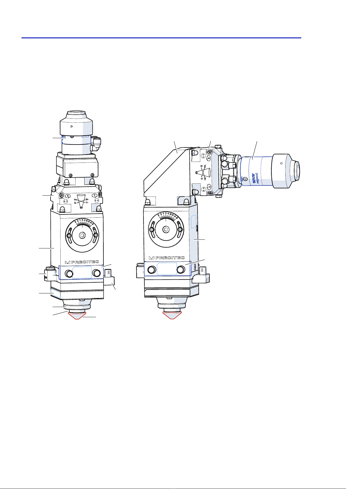
Fig. 2-1 Laser head, overall view
LC-BA-oAs / -oAa
5
2
6
7
3
10
1
9
8
11 2 1
3
10
(straight design)
(angled design)
4
1
Fibre socket
(e.g. QBH)
7
Ceramic part
KT
2
Collimating module
COL
8
Nozzle
DE
(nozzle electrode)
3
Adjustment module
(focal position)
9
BNC connection
(sensor system)
4
G1/8 connection, left
(cutting gas)
10
Protective window cartridge
5
Sensor insert
SE
11
Beam bender module
(COL 90°)
6
Nut
MU

2 Product description
D 159195 © Precitec GmbH & Co. KG • EN 09/2019
2-9
2.1.1 Design and functions
The laser head is used for the distance-controlled laser cutting of metals
using fibre-coupled lasers on flat bed machines.
It is precisely worked, rugged, service-friendly and can be adjusted easily.
All media connections are located at the laser head.
The laser head includes capacitive distance sensors that constantly record
the standoff distance between the nozzle
(nozzle electrode)
and the workpiece.
The system electronics analyses the sensor signal that is used to control a
linear drive.
Collimator
The collimator is permanently mounted on the laser head and mainly consist
of a fibre socket and the collimator housing with a water cooling device for the
collimating lens
(f
C
75 / f
C
100 focal length)
.
Water cooling device
All water-conducting parts in the module-integrated cooling system are made
of stainless steel. Fittings with M5 threaded holes for hoses
(ø6 mm external/
ø4 mm internal)
are used for cooling water outflow and inflow.
Laser beam position
The focal position adjustment device is integrated into the collimator.
Two Allen
(socket)
head screws
(size 2)
at the front of the collimator are used
for centring.
The horizontal adjustment range is ±1.5 mm.
Focusing lens
Focusing lenses with focal lengths from
F100
to
F200
can be used.
The maximum clear optical diameter
(clear aperture)
is 24 mm.
Focal position
(adjustment module)
The vertical adjustment range lies between -5 and +3 mm for all focal lengths.
A large indicating dial
(graduation of 0.5 mm)
enables the focal position to be set
using an Allen key
(size 5)
.
Protective window cartridge
The protective window cartridge is located underneath the beam shaping
optics. The protective window
(OG)
is pressure-proof and can withstand
maximum laser head pressure.
Cutting gas
The laser head can be operated at a cutting gas pressure of up to 25 bar
(2.5 MPa)
. The connection
(G1/8)
is located on the left-hand side of the
protective window module
(a module where the connection (G1/8) is on the
right-hand side is also available).
The cutting gas also cools the protective window.
Precitec offers fibre sockets for its high-performance collimators for connecting
conventional fibre optic cables
Collimators OG-COL
(straight design)
can also be equipped with a protective
window
(protective window cartridge COL)
which protects the collimating lens from
dust and dirt when the fibre is being installed or removed.
Cutting gas quality in compliance with ISO 8573-1:2010; Solid particles -
Class 2, Water - Class 4, Oil - Class 3 (see
Tab. 8-2, page 8-65
). The purer the
cutting gas is the longer the protective window's life will be.

2.1 Product - overall view
LightCutter
2-10
© Precitec GmbH & Co. KG • EN 09/2019 D 159195
Sensor insert
The sensor insert
(SE)
is fitted firmly to the laser head. It can be removed by
undoing four screws. A ceramic part
(KT)
is fitted to the sensor insert from
below. It locks into place firmly as it can only be fitted in one direction and is
secured by a nut
(MU).
Nozzle
(nozzle electrode)
The nozzle is screwed into the ceramic part and can be replaced easily if
worn. Precitec nozzles and ceramic parts are very precisely worked. Because
of the minimum concentricity tolerance any re-adjustment work can be
reduced or avoided when replacing these parts.
Fixing to the machine
Four M6 threaded holes
(14.5 mm deep)
at the back of the laser head are used
for fixing it to the machine. Two pin holes ø4
F7
(8 mm deep)
are used to position
the unit precisely and in such a way that this position can be reproduced.
2.1.2 Distance controller
Distance sensor system
(Lasermatic®)
For distance-controlled cutting, the laser head is equipped with the capacitive
Lasermatic®
distance sensor system
(sensor cable, max. 20 m)
.
Together with the other control loop components the system guarantees a
constant standoff distance
(focal position)
between the nozzle electrode and the
workpiece during laser beam cutting if there are no edges or large workpiece
surface bulges in the sensor's scanning range.
2.1.3 Protective equipment
Cooling the collimating lens
The collimating lens must be water-cooled. Fittings with M5 threaded holes for
hoses
(ø6 mm external/ ø4 mm internal)
are used for cooling water outflow and
inflow. The cooling water is conveyed around the collimator housing in a
(stainless steel)
circuit, indirectly cooling the collimating area.
Collision detection
When
Precitec
analysing electronics are used, an electronic collision signal is
emitted when the sensor insert or the nozzle contacts the machine mass. The
signal either stops the drive or enables the laser head to take evasive action.
Please refer to
chapter 8.2 „Parts available“, page 8-67
for the nozzle
(DE)
diameters that can be supplied.
This manual suits for next models
1
Table of contents
Popular Cutter manuals by other brands


Hilti
Hilti NCT 45 S-22 manual

Universal Laser Systems
Universal Laser Systems X-660 Safety, installation, operation, and basic maintenance manual

Guarda
Guarda FTR095 Operator's manual

Marshalltown
Marshalltown 28847 manual

Husqvarna
Husqvarna TS 230 I operating instructions

Yueming
Yueming CMA1325 owner's manual


