Muse M15 User manual

User Manual
Introduction and Safety
1.0 Support
1.1 Safety & Warnings
For Muse support, please go to
https://techsupport.signwarehouse.com/muse-vinyl-cutter-support-resources/
Please read the following safety guidelines regarding use of your Muse cutter:
Symbols inside triangles represent important notes that warrant your full attention. There are
dierent symbols denoting specic warnings. The symbol at left, for example, warns of a
possible danger of electric shock.
The cross-bar indicates activities that are prohibited because of risk of injury or possible
damage to your equipment. This particular symbol at left warns against the use of tools to
remove parts of the equipment.
Don't use with an electrical power source which doesn't meet the required voltage rating.
Using with substandard sources of electricity may result in re or electric shock.
Don't use your Muse if it begins to emit an odor or smoke.
Don't un-plug your Muse while powered on. Doing so may damage the equipment.
Make sure your Muse is grounded. Using your Muse without it being grounded may result in risk
of equipment damage or electric shock.
1
Thank you for choosing a Muse vinyl cutter.
Don't disassemble your Muse or attempt repairs unless directed by
SignWarehouse technical support.
Don't drop any liquids or metal objects into your Muse. Liquids or impact from hard
or heavy objects may damage the equipment.
Touching your Muse’s blade with your nger may result in injury.
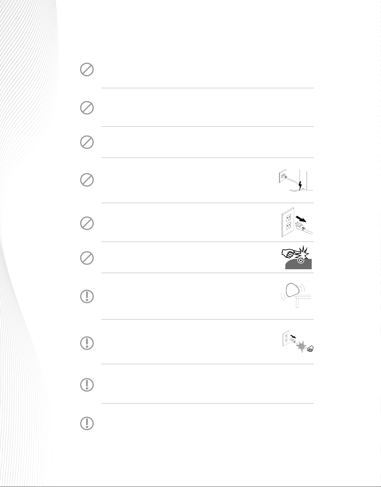
Don't damage or replace the power cable supplied with the vinyl cutter. Don't
excessively bend, pull, or fold the power cable or place weight on it. Crimping
the power cable may result in risk of failure or electric shock.
If you're not going to use your Muse for a long time, unplug the power
cable from the outlet.
Placing your hands on the cutting platen during operation may result in injury.
Place your cutter on a stable surface. Operating the vinyl cutter on an
unstable surface may result in a fall that can damage the equipment or
internal components.
To unplug the power cable from a receptacle, always grasp the plug
instead of the cable. Pulling the cable may damage it and increase
the risk of re or electric shock.
Don't operate during an electrical storm where lightning is present. For protection
against power surges, a surge protector is recommended.
Don't physically move the cutting head while your Muse is powered on. Manually
moving the cutting head during operation may damage the main board.

11 1
1.3 Warranty
1.4 Muse Contents & Accessories
The Muse cutter comes with a one-year parts warranty. If you have any questions about your cutter’s warranty,
please contact SIGNWarehouse via our warranty claim form at techsupport.signwarehouse.com.
It is recommended that you keep your original box with the Styrofoam packing materials in case your Muse
must be shipped or returned to SIGNWarehouse.
Besides the cutter, your box should also contain the following items:
Accessories Box containing all of the
following except for the Cutting Mat
Power Adaptor
M15 M24 M60
Power Cable
USB Cable (white or blue)
30° Blade
45° Blade
60° Blade
Blade Holder
Test Pen
Engraving Tool
Creasing Tool
Cutting Mat
11 1
-1 1
11 1
11 1
1- -
22 2
-1 1
21 1
21 1
-- 1
1- -
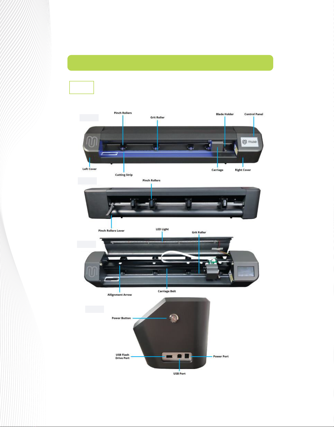
1.5 Parts of the Muse Cutter
Parts of the Muse 15 and 24
1.5.1
Fig. 1.5.3
Fig. 1.5.4
Fig. 1.5.2
Fig. 1.5.1
Right Cover

Parts of the Muse 60
1.5.2
Fig. 1.5.5
Fig. 1.5.6
Fig. 1.5.7
1.6 Accessories
1.7 Pinch Rollers
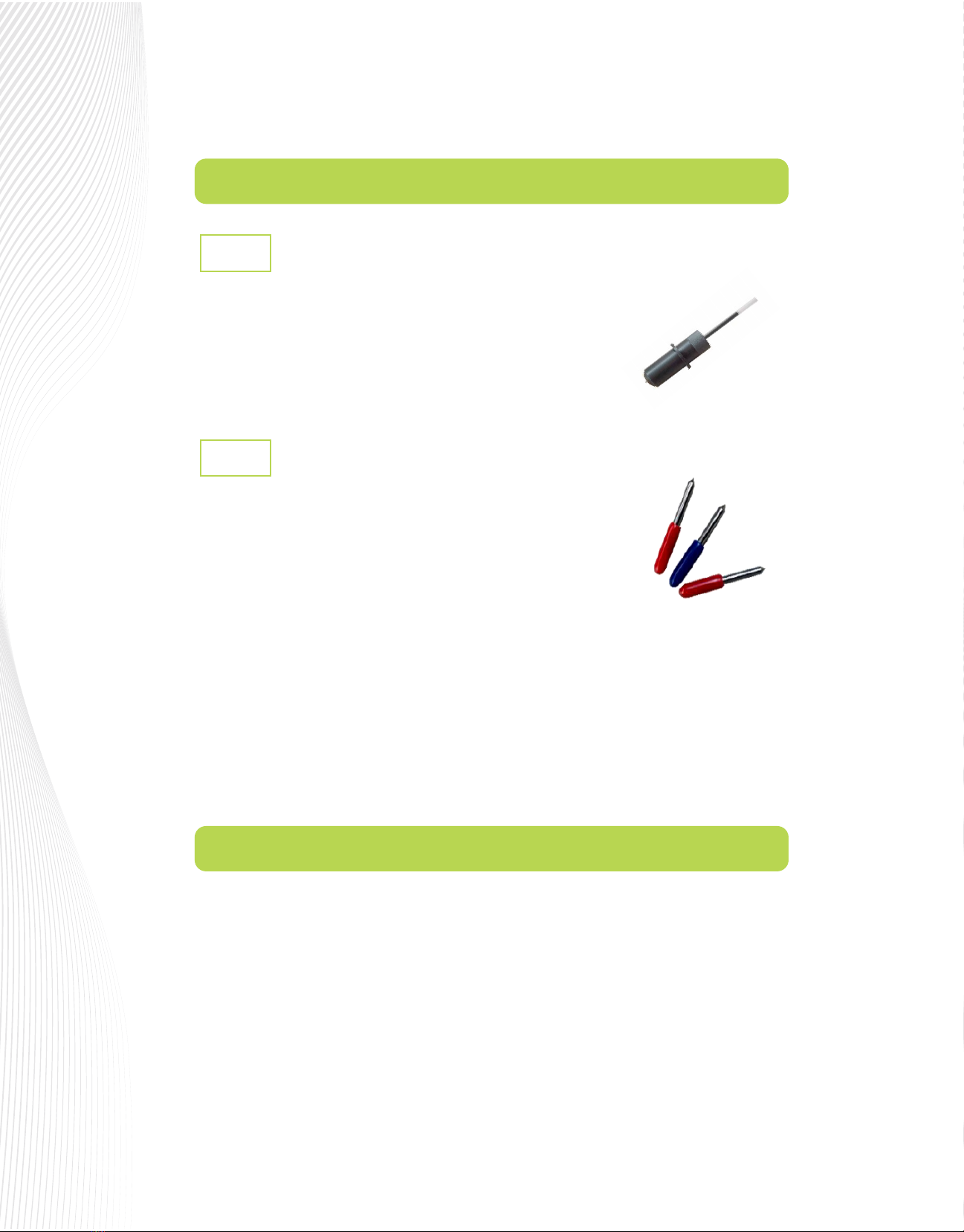
The test pen is used in calibrating the Muse’s camera (Section 3.01),
calibrating the Scale (Section 2.07), and is also recommended for test
drawing while you are learning where shapes will cut based on various
software settings. Note that a small piece of wax needs to be removed from
the pen’s nib before use. You may also wish to cut o the very top of the pen
rell so that it more easily ts into your Muse:
Your Muse is designed for cutting rolls and sheets of adhesive-backed lms such as vinyl, stencil mask and
sandblast etching lms. It can also use the included cutting mat for non-backed materials such as paper,
cardstock, magnet sheets and Mylar.
Press down the lever on the back of your M15 or M24 to raise the pinch rollers. On the M60 model, there are
individual levers on each pinch wheel which are lifted instead.
Insert the media into the space between the pinch roller and grit roller and pull out the media far enough to
ensure that it is loaded straight. The edges of the vinyl should be parallel to the left and the right frame of the
cutting platen. (A ‘platen’ is the lower plate that supports the vinyl as it passes through the cutter.)
The 30° yellow capped blade (not shown) is well-suited for window
tint and fabric. It is included with the M60.
The 45° red capped blade is well-suited for cutting thinner materials such as heat transfer vinyl and
wall/auto/decal vinyl. Two of these are included with the Muse.
The 60° blue capped blade has a longer cutting edge and is well-suited for cutting thicker materials like
sandblast stencil, ock, craft foam, magnet sheets, light chipboard, rhinestone template materials, etc. It
is included with the M15 and the M24.
Installing the blades into the blade holder is covered in Section 2.01. Blade Oset is covered in Section
2.02.2.
1.
2.
3.
Test Pen
1.6.1
Muse Blades
1.6.2
There are two kinds of blades that came with your Muse (note that which two
kinds dier depending on the model you purchased).
1.8 Control Panel
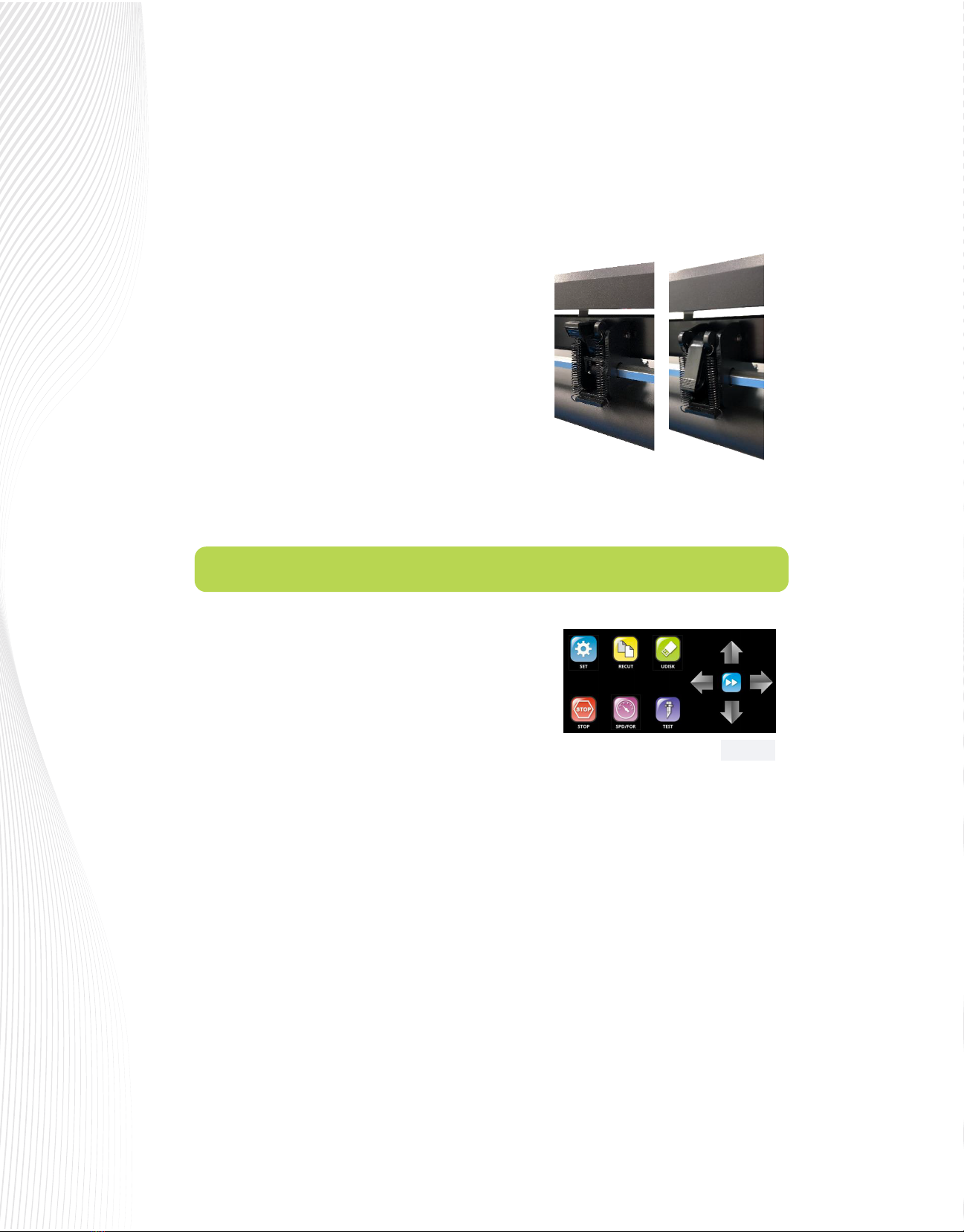
When you rst power on the Muse, the following Main Screen
or Home Screen will be displayed after several seconds:
The functions of the buttons on this Main Screen are:
SET: Opens the SETTING menu with access to other functions,
such as CAMERA, WI-FI, ARRAY, ADVANCED SETTINGS, etc.
See Section 1.8.1.
RECUT: Recuts the last job which is stored in the Muse’s memory. Note that while the Muse is cutting, this
button will read PAUSE. Pressing it will pause the cutting process in case any changes need to be made.
Pressing again will resume the cut.
UDISK: Opens the UDISK window allowing access to les on a USB thumb drive plugged into the Muse’s USB
Flash Drive port. Files must be saved in .PLT format to appear in the menu (See Sections 1.10.6 – 1.10.8 for
details).
STOP: One-touch emergency stop button stops the cutter and cancels the cut.
SPD/FOR: This button opens the SPEED/FORCE screen where you can optionally set the cutting speeds and
force of the cutter, as well as access the stored presets (See Sections 2.2-2.5).
TEST: Press the TEST button to cut a small square. This is recommended to ensure a clean cut is achieved with
the current settings before proceeding with a cut job.
Slide the pinch roller assemblies left and right so that the pinch rollers are centered over the grit roller.
The positions of the exposed grit rollers in the platen are marked by white arrows above the platen.
You may raise the cover above the tool carriage to see the arrows more clearly. Be sure to close it
before cutting.
Once the pinch rollers are in position, lower them to keep
your media in place. When using the cutting mat, you
need at least two wheels near the outside edges of the
mat, thus center the mat inside the cutter (versus having it
all the way to one side).
Each pinch roller on the M15 and M24 has a little lever on
the back side. These levers adjust the amount of pressure
applied to the media. Increasing the pressure can help
with slicker or thinner media such as heat transfer lm. It
may be advisable to reduce the pressure to accommodate
thicker materials like glass etch stencil. For normal use, like heat
transfer vinyl and sign vinyl, keep the levers in the higher position:
Fig. 1.8.1
Arrows: The left-right arrows move the tool carriage while the up-down arrows move the grit rollers.
This allows you to start cutting anywhere on the media (i.e. set an origin).
Double Arrow: The double arrow button controls the speed of the tool carriage and grit rollers while
setting a new origin. The default setting is the faster mode. Pressing this button once will change the
color of the button from blue to red, which indicates the slower mode. This mode can be used for very
precise movement.
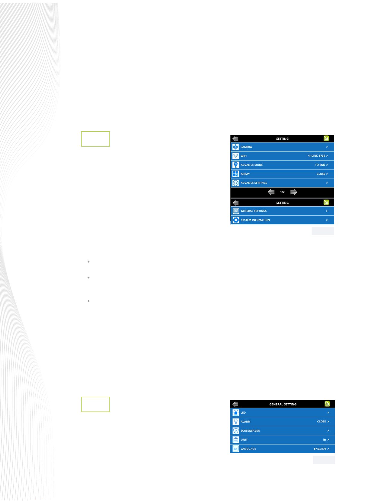
Setting Menu
1.8.1
The Setting menu provides access to seven additional
screens on two dierent pages:
These various functions and settings are:v
TO START: return the blade holder to the origin (the location immediately before the cut was started
TO END: advance the blade holder to the top of the completed cut with the option to move an additional
distance
To LEFT: advance the blade holder to the left of the completed cut with the option to move an additional
distance
ARRAY: Set up rows and columns of repeats with desired spacing (refer to Section 1.8.4)
ADVANCE SETTINGS: Refer to Section 1.8.3.
GENERAL SETTINGS: Refer to Section 1.8.2.
SYSTEM INFORMATION: Hardware and rmware versions, Baud rate, and other settings that should need no
adjustment unless directed by a SignWarehouse technical representative.
General Settings
1.8.2
Press SET on the Muse control panel and select GENERAL
SETTINGS. The optional settings are:
CAMERA: Opens the CAMERA SETTINGS menu.
Refer to Section 3.00.
WIFI: Connect the MUSE to your home or oce router for
wireless connectivity (refer to Sections 1.10.4 and 1.10.5).
ADVANCE MODE: Three options for where the blade holder goes at the end of a cut:
Fig. 1.8.2
Fig. 1.8.3
LED: This option allows you to customize the platen lighting in your Muse.
On the M15 and M24, the default color is a cool blue. But if blue isn’t your cup of tea, you can change on this
screen. There are slider bars to help pick a custom color. You can also turn o the LED platen lighting if you
wish. Note: In case of an error during cutting, the LED platen lighting will immediately turn red to indicate an
alarm condition.
On the M60, you can change the intensity of the white light according to your personal preference.
.
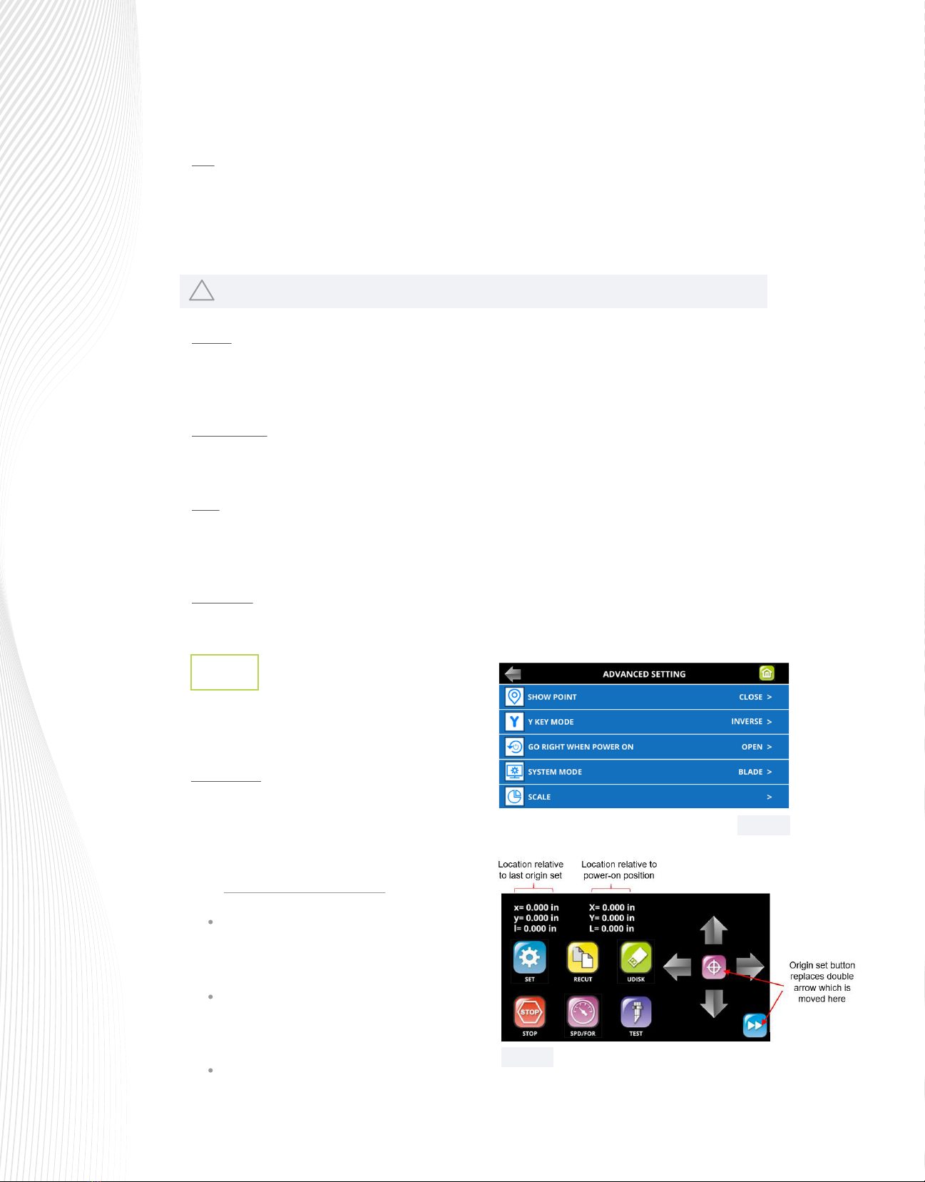
Advanced Settings
1.8.3
Press SET on the Main Screen and select ADVANCE
SETTINGS. The optional settings are:
SHOW POINT: This feature shows the origin point
of your cut jobs. When toggled on, the Main Screen
will display an updated center button used to reset
the origin, as well as some location positions:
Absolute Location displays the current location relative
to the “power-on” origin point of (0,0):
!
Xis the position relative to the movement of the
cutter’s tool carriage from left to right across the
platen.
Yis the position relative to the forward and
backward motion of the media as it is fed by the
grit rollers.
Lis the straight-line distance from Xto Y.
ALARM: Enabling ALARM AFTER COMPLETED will produce an audible alarm of 5 beeps once a job completes.
Uncheck this box if you wish to turn o this feature. Similarly, enabling LED AFTER JOB COMPLETED will change
the LED color to blue once a job completes.
This feature is only on the M15 and M24 models.
SCREENSAVER: After a predetermined period of time, the cutter goes into standby mode to save energy and the
LCD screen will darken as the cutter goes to sleep. You can change the amount of time before sleep mode
begins.
UNIT: This setting allows you to choose the unit of measurement for all functions involving distance, such as the
spacing between repeats or position of the cutting head. The default setting is MILLIMETERS (mm). The other
option is INCHES (in). Because the SPEED and FORCE settings on a Muse are based on a scale versus units, they
remain the same whether you are in imperial mode or metric.
LANGUAGE: This screen oers a choice of three languages: English, Spanish, and Mandarin. You can choose one
of these for the language in which all settings and menu communication are displayed
Fig. 1.8.4
Fig. 1.8.5
This manual suits for next models
2
Other Muse Cutter manuals

Popular Cutter manuals by other brands

Milwaukee
Milwaukee HEAVY DUTY M12 FCOT Original instructions

Makita
Makita DCS552 instruction manual

SignWarehouse.com
SignWarehouse.com Bobcat BA-60 user manual

Makita
Makita 4112HS instruction manual

GEISMAR STUMEC
GEISMAR STUMEC MTZ 350S manual

Hitachi
Hitachi CM 4SB2 Safety instructions and instruction manual


