Universal Laser Systems X-660 Setup guide

X-660 / X2-660
SuperSpeed-660
Laser Engraving and Cutting Systems
Safety, Installation, Operation,
and Basic Maintenance Manual
Universal Laser Systems, Inc.
16008 North 81st Street
Scottsdale, AZ 85260 USA
Customer Support Department
Phone: 480-609-0297
Fax: 480-609-1203
Web Based Email Support: www.ulsinc.com
August 2005

Notice
This publication and its contents are proprietary to Universal Laser Systems, Inc. (ULS), and are intended
solely for the contractual use of ULS, Inc. customers.
While reasonable efforts have been made to assure the accuracy of this manual, ULS shall not be liable
for errors contained herein or for incidental or consequential damage in connection with the furnishing,
performance, or use of this material. ULS reserves the right to revise this manual and make changes from
time to time without obligation by ULS to notify any person of such revision or changes.
ULS does not assume any liability arising out of the application or use of any products, circuits, or
software described herein. Neither does it convey a license under its patent rights nor the patent rights of
others.
This publication and its contents may not be reproduced, copied, transmitted, or distributed in any form,
or by any means, radio, electronic, mechanical, photocopying, scanning, facsimile, or otherwise, or for
any other purpose, without the prior written permission of ULS.
ULS provides no warranties whatsoever on any software used in connection with a ULS Laser Engraving
System, express or implied. Neither does it guarantee software compatibility with any off-the-shelf
software package or any software program that has not been written by ULS.
Intended use of this system must be followed within the guidelines of this manual. In no event will ULS
be liable for any damages caused, in whole or in part, by customer, or for any economic loss, physical
injury, lost revenue, lost profits, lost savings or other indirect, incidental, special or consequential
damages incurred by any person, even if ULS has been advised of the possibility of such damages or
claims.
WARNING: UNIVERSAL LASER SYSTEMS PRODUCTS ARE NOT DESIGNED, TESTED, INTENDED
OR AUTHORIZED FOR USE IN ANY MEDICAL APPLICATIONS, SURGICAL APPLICATIONS,
MEDICAL DEVICE MANUFACTURING, OR ANY SIMILAR PROCEDURE OR PROCESS REQUIRING
APPROVAL, TESTING, OR CERTIFICATION BY THE UNITED STATES FOOD AND DRUG
ADMINISTRATION OR OTHER SIMILAR GOVERNMENTAL ENTITIES. SHOULD THE BUYER USE
UNIVERSAL LASER SYSTEMS PRODUCTS FOR ANY SUCH UNINTENDED OR UNAUTHORIZED
APPLICATION, ALL WARRANTIES REGARDING THE UNIVERSAL LASER SYSTEMS PRODUCTS
SHALL BE NULL AND VOID. FURTHER, THE BUYER SHALL HAVE NO REMEDY AGAINST
UNIVERSAL LASER SYSTEMS AND ITS OFFICERS, EMPLOYEES, SUBSIDIARIES, AFFILIATES AND
DISTRIBUTORS FOR, AND THE BUYER SHALL INDEMNIFY AND HOLD THOSE PARTIES
HARMLESS AGAINST, ANY AND ALL CLAIMS, COSTS, DAMAGES, EXPENSES AND REASONABLE
ATTORNEY FEES ARISING OUT OF, DIRECTLY OR INDIRECTLY, ANY CLAIM ASSOCIATED WITH
SUCH UNINTENDED OR UNAUTHORIZED USE, INCLUDING BUT NOT LIMITED TO ANY CLAIM
BASED ON WARRANTY (EXPRESS OR IMPLIED), CONTRACT, TORT (INCLUDING ACTIVE,
PASSIVE, OR IMPUTED NEGLIGENCE), STRICT LIABILITY, PATENT OR COPYRIGHT
INFRINGEMENT OR MISAPPROPRIATION OF INTELLECTUAL PROPERTY.
HP is a registered trademark of Hewlett-Packard Corporation.
Windows is a registered trademark of Microsoft Corporation.
Macintosh is a registered trademark of Apple Computer Corporation.
PostScript, Photoshop, and Streamline are registered trademarks of Adobe Systems Inc.
CorelDRAW is a registered trademark of Corel Corporation.
AutoCAD is a registered trademark of AutoDesk Inc.
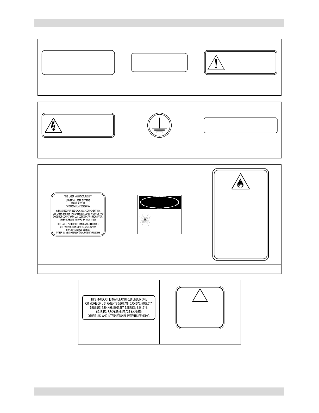
ULS Platforms are protected under one or more of U.S.
patents 5,661,746; 5,754,575; 5,867,517; 5,881,087;
5,894,493; 5,901,167; 5,982,803; 6,181,719; 6,313,433;
6,342,687. Other U.S. and International patents pending.
© Universal Laser Systems Inc., 2005
All Rights Reserved

Introduction
We would like to thank you for your laser system purchase. Universal Laser Systems, Inc. (ULS) is the
pioneer, and highest volume manufacturer, of large field, computer controlled laser engraving, marking,
and cutting systems. ULS has devoted years of research and development to further the quality of our
products that has resulted in a number of remarkable innovations within the laser industry. Since 1988,
the staff at ULS has been dedicated to total customer satisfaction. When you buy Universal you get more
than a laser - you get a team of talented, experienced, enthusiastic people who are focused on your
satisfaction. Our commitment is to help you now and in the future.
To begin with, we highly recommend that this entire manual be read before attempting to use your laser
system. The manual includes important information about safety, assembly, use, troubleshooting, and
basic maintenance.
How To Get Help
Before contacting our Technical Support Department, make sure that you have read this entire manual as
well as any other accompanying manuals included with your laser system. The Troubleshooting Guide,
found within this manual, is very comprehensive and provides the answers to frequently asked questions.
Step 1:
Try to recreate the problem and write down the circumstances in which the problem occurred. Try to
recall if the problem began all of a sudden, worsened over time, or began after you performed any recent
maintenance. Also be prepared to describe all pertinent information about the computer being used such
as software, ULS printer driver version, computer operating system and computer type.
Step 2:
Make sure that you have the serial number of the laser system available. The serial number tags are
located on the back of the machine, next to the exhaust port, and inside the front door, visible when you
open it. The Technical Support Department may not be able to assist you without this number.
Step 3:
Contact your local ULS Representative. They may have more details about your particular installation and
applications. If possible, call from a phone that is close to the laser system so that it can be operated
while talking to our representative.
Step 4:
If your local Sales Representative cannot assist you and you would like to use our FREE, email based
support system, log on to our website: www.ulsinc.com. Click on the “Technical Support “ link, then click
on the “Technical Support Request Form” and follow the instructions.
Step 5:
If you are unable to obtain Internet access, you may contact our Technical Support Department at:
Universal Laser Systems, Inc.
Technical Support Department
16008 North 81st Street
Scottsdale, AZ 85260
Phone: 480-609-0297
Fax: 480-609-1203
M-F 8am – 5pm Arizona Time

Specifications
System Operating Environment Requirements (user provided)
Operating Environment Well-ventilated office (recommended) or clean, light-duty manufacturing
Operating Temperature 50ºF (10ºC) to 95ºF (35º C) capable
73ºF (22ºC) to 77ºF (25º C) for best performance
Storage Temperature 50ºF (10ºC) to 95ºF (35º C)
Operating Humidity Non-condensing
Electrical Power Single Phase 100/220V AC, 10/5 Amp, 50/60 Hz
Grounded (earthed) and stable (surge and spike protected)
Particulate/Odor Outside
Ventilated Exhaust System High-pressure vacuum blower capable of
500 CFM (cubic feet per minute) @ 6 inches static pressure
(850m3/hr at 1.5kPa)
Computer Requirement Windows 95/98 or Windows 2000/XP compatible
Software Requirement Graphics or CAD based
(See manual for recommendations)
System Specifications
Laser Safety CO2 Laser, Interlocked Safety Enclosure = Class I
Red Diode Pointer = Class IIIa
Laser Source 25,30,35,40,45,50,55,or 60 watt CO2 Laser Cartridge
1 or 2 Laser Cartridges can be installed on the X2-660 or the
SuperSpeed-660 Platforms
Work Area 32” x 18” (812.8 x 457.2 mm)
Printer Driver Windows 95/98 and Windows 2000/XP compatible
Hardware Interface Centronics Parallel (included)
RS232C Serial, USB, or Ethernet adapter options available
Memory Buffer 16 MB standard, single and multiple file storage modes with automatic data
compression
Dimensions 36.5”L x 44”W x 39.5”H
(92.7cm L x 111.8cm W x 100.3cm H)
System Weight System = 325 lbs. (147 kg)
Laser Cartridge Weight 25/30 Watt = 20 lbs (9 kg)
35/40 Watt = 23 lbs (10 kg)
45/50/55/60 Watt = 26 lbs (12 kg)
Available Options Rotary Fixture, Air Assist (standard or computer controlled), Air Compressor
(desiccant or refrigerated dryer options), Honeycomb Cutting Table, Dual
Head, Assorted Focal Length Lens Kits
Specifications subject to change without notice

Table of Contents
Section 1 - Safety
Description of Appropriate Use........................................................................................1-1
General Safety.................................................................................................................1-1
Laser Safety.....................................................................................................................1-2
Safety Labels ...................................................................................................................1-2
EU Compliance (CE)........................................................................................................1-4
FCC Compliance..............................................................................................................1-5
Recycling..........................................................................................................................1-5
Section 2 - Installation
System Operating Environment Requirements ...............................................................2-1
System Assembly.............................................................................................................2-3
Finalizing the Connections...............................................................................................2-6
Printer Driver Installation..................................................................................................2-7
Section 3 – Basic System Operation
The Control Panel............................................................................................................3-1
The Menu System............................................................................................................3-2
Focusing Methods............................................................................................................3-5
Making a Sample, Step-by-Step......................................................................................3-7
How it All Works...............................................................................................................3-9
Section 4 - Basic Maintenance
Motion System Components Diagram.............................................................................4-1
Cleaning and Maintenance Supplies ...............................................................................4-2
System Cleaning and Maintenance.................................................................................4-2
Maintenance Schedule.....................................................................................................4-5
Troubleshooting ...............................................................................................................4-6
Section 5 – Material Settings Guide
Acrylic – Cast and Extruded.............................................................................................5-4
Acrylic - Mirrored..............................................................................................................5-6
Aluminum - Anodized.......................................................................................................5-8
Brass – Painted................................................................................................................5-9
Corian / Avonite / Fountainhed ......................................................................................5-10
Cork................................................................................................................................5-11
Delrin..............................................................................................................................5-12
Glass/Crystal..................................................................................................................5-13
Leather...........................................................................................................................5-14
Marble ............................................................................................................................5-15
Mat Board.......................................................................................................................5-16
Melamine - Standard......................................................................................................5-17
Melamine – Photo/Clipart engraving..............................................................................5-18
Plastic – Microsurfaced..................................................................................................5-19
Rubber Stamps..............................................................................................................5-20
Vinyl – Sign....................................................................................................................5-21
Wood / Wood Inlay.........................................................................................................5-22
Section 6 – Accessories
Air Assist ..........................................................................................................................6-1
Air Assist Compressor......................................................................................................6-7
Dual Head........................................................................................................................6-8
Honeycomb Cutting Table .............................................................................................6-11
Focus Lens Kits..............................................................................................................6-13
Rotary Fixture.................................................................................................................6-14


Section 1
Safety
Description of Appropriate Use
This device is designed for laser cutting and engraving of the materials listed in this manual, in a
laboratory, workshop, or light duty manufacturing environment. Materials to be processed must fit
completely inside the system for proper operation.
Notice: This device is not designed, tested, intended or authorized for use in any medical
applications, surgical applications, medical device manufacturing, or any similar procedure or
process requiring approval, testing, or certification by the United States Food and Drug
Administration or other similar governmental entities. Please see the Notice herein for further
information regarding such uses.
General Safety
Use of the equipment in a manner other than what is described in this manual can result in injury to
yourself, others, or may cause severe damage to the equipment and your facility. Failure to follow the
operational requirements and safety guidelines, listed in this manual, may increase this risk.
•Exposure to the laser beam may cause physical burns and can cause severe eye damage.
Proper use and care of this system are essential to safe operation.
•Never operate the laser system without constant supervision of the cutting and engraving
process. Exposure to the laser beam may cause ignition of combustible materials and start a fire. A
properly maintained fire extinguisher should be kept on hand at all times.
•A properly configured, installed, maintained, and operating particulate/fume exhaust system is
mandatory when operating the laser system. Fumes and smoke from the engraving process must
be extracted from the laser system and exhausted outside.
•Some materials, when engraved or cut with a laser, can produce toxic and caustic fumes. We
suggest that you obtain the Material Safety Data Sheet (MSDS) from the materials manufacturer.
The MSDS discloses all of the hazards when handling or processing that material. DISCONTINUE
processing any material that shows signs of chemical deterioration of the laser system such as rust,
metal etching or pitting, peeling paint, etc. Damage to the laser system from caustic materials is NOT
covered under warranty.
•Care should be taken when moving or lifting this device. Obtain assistance from 1 or 2 additional
people when lifting or carrying (secure motion system and doors). Severe bodily injury may occur if
improper lifting techniques are applied or the system is dropped.
•Dangerous voltages are present within the electronics and laser enclosures of this system.
Although access to these areas is not necessary during normal use, if it becomes necessary to open
one of these enclosures for service reasons please remember to disconnect the power cord from your
electrical supply.
•This device is specifically designed to comply with CDRH performance requirements under 21
CFR 1040.10 and 1040.11. CDRH is the Center for the Devices of Radiological Health division of the
Food and Drug Administration (FDA) in the USA. It also complies with CE (European Community)
safety regulations. No guarantees of suitability or safety are provided for any use other than those
specified by Universal Laser Systems, Inc.

SAFETY
Section 1-2
Laser Safety
The device contains a sealed carbon dioxide (CO2) laser in a Class I enclosure that produces intense
invisible and visible laser radiation at a wavelength of 10.6 microns in the infrared spectrum. For your
protection, this enclosure is designed to completely contain the CO2 laser beam. Improper use of
controls and adjustments, or performance of procedures other than those specified, may invalidate the
safety of this system.
•The intense light that appears during the engraving or cutting process is the product of material
combustion or vaporization. DO NOT STARE AT THE BRIGHT LIGHT OR VIEW DIRECTLY WITH
OPTICAL INSTRUMENTS.
•This device may contain a visible Red Dot Pointer (Class IIIa). DO NOT STARE AT THE RED LIGHT
OR VIEW DIRECTLY WITH OPTICAL INSTRUMENTS.
•The user door(s) are safety interlocked and will disable the CO2 laser beam from firing when the user
door(s) are opened. The Red Dot Pointer is NOT safety interlocked and can be activated with the
door(s) either open or closed.
•Do not operate any system that has had its safety features modified, disabled, or removed as this can
expose your eyes and skin to invisible and visible CO2 laser radiation which can cause permanent
blindness and/or severe burns to your skin.
Safety Labels
CDRH and CE regulations require that all laser manufacturers affix warning labels in specific locations
throughout the equipment. The following warning labels are placed on the laser system for your safety.
DO NOT remove them for any reason. If the labels become damaged or have been removed for any
reason, DO NOT OPERATE the laser system and immediately contact Universal Laser Systems, Inc. for
a free replacement. Labels are NOT to scale.
Model No:
Serial No: Made in USA
Manufactured:
Scottsdale, Arizona
LASER SYSTEMS INC.
XXXXX
XXXXX
XXXXX
SERIAL #: XXXXX
DATE: XXXXX
WARNING
NEVER OPERATE THE LASER SYSTEM
WITHOUT CONSTANT SUPERVISION
EXPOSURE TO THE LASER BEAMMAY
CAUSE IGNITION OF COMBUSTIBLE
MATERIALS WHICH CAN CAUSE SEVERE
DAMAGE TO THE EQUIPMENT
221-0004-0 221-0007-0 221-0012-0
!
WARNING
THIS LASER SYSTEM CONTAINS A
CO LASER IN A CLASS I ENCLOSURE.
THE LASER SYSTEM HAS BEEN
CLASSIFIEDAS CLASS 3R DUE
TO THE PRESENCE OF A
VISIBLE LASER DIODE.
2
THIS EQUIPMENT CONFORMS
TO PROVISIONS OF
US 21 CFR 1040.10
AND 1040.11
DANGER
INVISIBLEANDVISIBLELASERRADIATION
ANDINTERLOCKFAILEDOR
AVOIDEYEORSKINEXPOSURE
DIRECTORSCATTEREDRADIATION
WHENOPEN
DEFEATED
TO
221-0013-0 221-0015-0 221-0016-0

SAFETY
Section 1-3
DANGER
INVISIBLE AND VISIBLE LASER
RADIATION WHEN OPEN
AVOID EYE OR SKIN EXPOSURE TO
DIRECT OR SCATTERED RADIATION
AVOID EXPOSURE
INVISIBLE LASER RADIATION IS
EMITTED FROM THIS APERTURE
WARNING
TURN THE LASER SYSTEM OFF BEFORE
CONNECTING OR DISCONNECTING
THE ROTARY FIXTURE
221-0017-0 221-0018-0 221-0019-0
WARNING
TO AVOID RISK OF ELECTRIC SHOCK
ALWAYS DISCONNECT POWER CORD
BEFORE REMOVING THIS COVER
INPUT POWER:
220 VAC; 50/60 Hz; 15 A
221-0020-0 221-0021-0 221-0024-0
LASER RADIATION -AVOID
DIRECTEYE EXPOSURE
CLASS3R LASER PRODUCT
LASERDIODE
WAVELENGTH:630-680nm
MAX.OUTPUT: 5 mW
DANGER
WARNING
THIS SYSTEM IS DESIGNED FOR
USE WITH INERT AND
NON-OXIDIZING GASES ONLY
(i.e. DRY CLEAN AIR, CARBON
DIOXIDE, HELIUM, NITROGEN).
CONNECTING FLAMMABLE OR
OXIDIZING GASES TOTHIS
SYSTEM CREATES A SERIOUS
SAFETY AND/OR FIRE HAZARD.
DO NOT CONNECT ANY GAS
SOURCESEXCEEDING 75 PSI
(5 ATM) PRESSURE.
UNIVERSAL LASER SYSTEMS
ASSUMES NO RESPONSIBILITY
ARISING FROM THE IMPROPER
USE OF THIS SYSTEM.
221-0031-0 221-0034-0 221-0037-0
!
WARNING
Do use in medical or surgical
applications or to manufacture
medical devices. See the Safety,
Installation, Operation, and Basic
Maintenance Manual, or the OEM
Laser Integration Manual for
further information.
NOT
221-0065-0 221-0081-0

SAFETY
Section 1-4
221-0016-0 221-0012-0 221-0013-0
221-0033-0
221-0034-0
221-0018-0
221-0007-0
221-0018-0
221-0007-0 221-0031-0 221-0017-0
221-0044-0
221-0045-0
221-0046-0
221-0047-0
221-0048-0
221-0049-0
221-0050-0
221-0051-0
221-0016-0
221-0021-0
221-0016-0
221-0020-0
221-0024-0
221-0037-0
221-0004-0
221-0015-0
221-0065-0 221-0081-0

SAFETY
Section 1-5
EU Compliance (CE)
Product Identification: X-660, X2-660, and SuperSpeed-660
Laser Engraving and Cutting Systems
Manufacturer: Universal Laser Systems, Inc.
16008 N. 81st St.
Scottsdale, AZ 85260
Phone: (480) 483-1214 Fax: (480) 483-5620
USA
This equipment Is manufactured in conformity with the following directives:
89/336/EEC (EMC Directive)
73/23/EEC (Low Voltage Directive)
98/37/EEC (Machinery Directive)
based on the standards listed.
Standards Used:
Safety: EN 60950: 2002
EN 60825: 2001 (Class 3R)
EMC: EN 55022: 2003 (Class A)
EN 50082-1: 1998
EN 61000-3-2: 2001 (class A)
EN 61000-3-3: 2002
EN 61000-4-2: 2001 (6kV CD, 8kV AD)
EN 61000-4-3: 2003 (3 V/m)
EN 61000-4-4: 2002 (2 kV power line, 0.5 kV signal line)
EN 61000-4-5: 2001 (class 2)
Note: This is not a declaration of conformity. The importer of this equipment
supplies the declaration of conformity.
LASER SYSTEMS INC.
Warning - This is a Class A product. In a domestic environment, this product
may cause radio interference in which case the user may be required to take
adequate measures.

SAFETY
Section 1-6
FCC Compliance
This ULS laser system has been tested and found to comply with Federal Communication Commission
(FCC) directives regarding Electromagnetic Compatibility (EMC). In accordance with these directives ULS
is required to provide the following information to its customers.
FCC Compliance Statement and Warnings
This device complied with FCC Rules Part 15. Operation is subject to the following two conditions:
1. This device may not cause harmful interference, and
2. This device must accept any interference received, including interference that may cause
undesired operation.
This equipment has been tested and found to comply with the limits for a Class A digital device as set
forth in Part 15 of the FCC Rules. These limits are designed to provide reasonable protection against
harmful interference when the equipment is operated in a commercial environment. This equipment
generates, uses and can radiate radio frequency energy and, if not installed and used in accordance with
manufacturer’s instructions, may cause harmful interference to radio communications. Operation of this
equipment in a residential area is likely to cause harmful interference in which case the user will be
required to correct the interference at his or her own expense.
Users should be aware that changes or modifications to this equipment not expressly approved by the
manufacturer could void the user’s authority to operate the equipment.
This equipment has been type tested and found to comply with the limits for a Computing Device per FCC
part 15, using shielded cables. Shielded cables must be used in order to insure compliance with FCC
regulations.
Recycling
By placing the above symbol on our products and accessories Universal Laser Systems is indicating that
we are committed to helping reduce the amount of waste electronics ending up in municipal landfills.
Therefore Universal Laser Systems urges consumers to recycle this product and its accessories.
Universal Laser Systems is equipped to recycle any of its electronic products and accessories and will
assist our customers with their recycling options. To arrange for recycling of your ULS product or
accessory, please contact Universal Laser Systems for more information.

Section 2
Installation
The following operational guidelines are vital to a safe and productive environment. It is your
responsibility to provide a proper operating environment.
Damage to the laser system due to an inadequate or improper operating environment is
considered abuse and WILL NOT be covered under warranty. In no event will ULS be
liable for any damages caused, in whole or in part, by customer, or for any economic
loss, physical injury, lost revenue, lost profits, lost savings or other indirect, incidental,
special or consequential damages incurred by any person, even if ULS has been advised
of the possibility of such damages or claims.
System Operating Requirements
Environment (user supplied)
•The laser system MUST be installed in an office-type or light duty manufacturing environment. Dusty
or dirty air environments can damage the laser system. Keep the laser system isolated from any type
of sandblasting, sanding, oily, or any other machinery that produces airborne particles.
•Avoid small, enclosed, non-ventilated areas. Some materials, after laser engraving or cutting,
continue emitting fumes for several minutes after processing. Having these materials present in a
confined, unventilated room can contaminate the room.
•For best results, since the lasers are air-cooled, we recommend operating the laser system between
the ambient temperatures of 73ºF (22ºC) to 77ºF (25º C). However, the system can operate between
the temperatures of 50ºF (10ºC) to 95ºF (35º C).
•Avoid storing the laser system outside the temperatures of 50ºF (10ºC) to 95ºF (35º C) as excessively
cold or hot temperatures can damage the laser cartridge or reduce its lifetime.
•Ambient humidity levels must be non-condensing.
Electrical (user supplied)
•For your system’s electrical requirements, please refer to the “INPUT POWER” label near the
ON/OFF switch and/or power inlet.
•Never remove the ground lead to the electrical cord and plug the system into a non-grounded
outlet. This is very dangerous and can lead to a severe, if not fatal, electrical shock. Always plug the
system into a properly grounded (earthed) outlet. Also, without proper grounding, the laser system
may exhibit sporadic or unpredictable behavior.
•Noisy or unstable electricity as well as voltage spikes may cause interference and possible damage
to the electronics of the laser system. If electrical power fluctuations, brown outs, or constant power
outages are a problem in your area, an electrical line stabilizer, UPS (Uninterruptible Power Supply),
or backup generator might be required. You may also need to connect the laser system to a
dedicated electrical line to resolve the problem.
•The laser system is designed as a Class I, Group A, pluggable device. It is also designed for
connection to IT power systems which provides the most flexibility to the user.

INSTALLATION
Section 2-2
Exhaust System (user supplied)
•The exhaust system MUST be capable of supplying a minimum of 500 CFM (cubic feet per minute) of
airflow while under a load of 6 inches of static pressure (850m3/hr at 1.5kPa). DO NOT install
forward incline, backward incline, in-line, or ventilator fans because these types of air handlers are
inadequate and inappropriate for this type of installation. A high-pressure blower MUST be used to
meet minimum airflow requirements.
•The blower MUST be mounted on the OUTSIDE of the building.
•Rigid tubing should be used for 90% of the distance traveled between the blower and the laser
system. The tubing should be smooth walled and have as few 90 degree bends as possible.
•Install a gate to control airflow and to close off the exhaust from the outside environment when the
laser is not in use. Place this gate within 5 – 10 feet from the laser system.
•Use a short piece of industrial grade, wire reinforced rubber tubing to connect the end of the gate to
the laser system. This will provide mobility and will dampen blower vibrations.
•Have the blower electrically wired to a wall switch in the same room for easy ON/OFF control.
The following diagram shows a typical exhaust system layout. Use this as a guideline to proper exhaust
system installation. Although this diagram just serves as an example, we recommend installation of the
exhaust system by a licensed contractor to meet safety and local code requirements as well as being able
to calculate the correct size blower required for your particular installation. Length of exhaust pipe,
exhaust pipe diameter, number of 90-degree angles, and other restrictions must be calculated when
determining the correct exhaust blower unit. Installing an undersized or oversized blower is not only
unsafe, but it can also lead to
premature and excessive wear
and tear to the laser system.
1
2
3
4
5
6
9
8
3
4
5
6
7
6
8
7
(1) Exhaust blower mounted
outside.
(2) Weatherproof shield
(3) Rigid ducting matching the
diameter of the blower inlet
(4) Reducer to 4 inches
(5) Y-pipe
(6) Shut-off or air-flow gate(s)
(7) Flexible, wire-reinforced,
industrial grade rubber hose
(8) Connection to laser
(9) On/Off switch
Minimum PC Computer Configuration (user supplied)
500 MHz using Windows 95/98 or 2000/XP CD-ROM Drive/Burner
256 MB of RAM Mouse or other pointing device
2 Gigabyte hard drive or bigger 600 DPI Optical Resolution Scanner (optional)
17 inch color VGA monitor Internet connection and email address (optional)
Suggested Software (user supplied)
ULS does not guarantee software compatibility with any off-the-shelf software program that has not been
written by ULS. However, the following suggested programs are widely used by ULS customers and are
considered to be the most functional and compatible programs to use with the laser system.
•Graphics Programs (user supplied)
CorelDRAW, Macromedia Freehand, or Canvas
•Bitmap / Scanning Software (user supplied)
Corel PHOTO-PAINT or Adobe Photoshop

INSTALLATION
Section 2-3
•Raster to Vector Conversion Software (user supplied)
Adobe Streamline or CorelTRACE
•CAD Software (user supplied)
AutoCAD or AutoCAD LT for Windows
•FONTS (user supplied)
Use True Type fonts ONLY. Do not use PostScript or bitmapped fonts.
System Assembly
If the doorway is not wide enough to allow to you roll the laser system through it, the system MUST be
detached from the cart stand, rotated sideways, passed through the doorway, then re-attached to the cart
stand. If your doorway is wide enough, you can skip the following procedure and proceed to “Leveling the
System”. It would help if you had a PADDED floor dolly to transport the machine through the doorway. If
one is not available, it will need to be carried through the doorway.
The laser system without the cart stand weighs approximately 200 lbs. Obtain assistance
from as many people as possible (3 or 4 people). Always use a back-support device
when lifting. Do not attempt lifting the machine if you are physically handicapped or are
injured in any way. Seek the advice of a physician if you are unsure.
1. Make sure unit is unplugged from an electrical
outlet.
2. At the back of the system, locate the four
screws; remove them and the cover plate.
3. Locate the two, white connectors and the one,
black connector that attaches the wire harness
to the power supply. Unplug all three
connectors. They are held in place by latches
so you will need to release the latches to pull
the connectors off.
4. Open the rear cover by pressing down on the
button part of the latches until the latches pop
up.
5. Fold the rear cover down to a resting position.

INSTALLATION
Section 2-4
6. Locate the cavity where the cables reside. Gently
pull the cables upwards and rest them on top of the
gray-colored plate as the diagram indicates.
7. Close and re-latch the rear cover.
8. Remove any packing materials or accessories from
inside the laser system.
9. Using strong shipping tape or rope, tape the front
door closed so that it does not open up when you
tilt it.
10. Remove the eight (8) screws, flat washers, and lock
washers that attach the cart stand to the laser system
from the bottom.
11. Lift the laser system straight up, clearing the cart stand.
12. Place the laser system face down on the dolly and roll
it through the doorway. If you do not have a dolly, you
will need to carry it through.
13. After you get the laser system and the cart stand
through the door, carefully line up the laser system and
place it back on top of the cart stand. Be careful not
to pinch your fingers.
14. Attach your screws, flat washers, and lock washers.
Gently push the cables back into the cavity, re-connect
the three power supply connectors, re-attach the cover
plate, close the rear cover, and push down on the
latches until they “click”.
Leveling the System
Move the laser system to the desired operating
location. If the floor underneath the laser system, at
this location, is uneven, the casters must be adjusted.
Uneven flooring can cause mechanical problems
with the operation of the motion system, which can
seriously affect engraving or cutting quality.
1
2
3
4
5
1. Place a bubble level across the front (2) and rear
legs (3). Adjust the caster height using the
adjustment screw (4) until both the rear part and
the front part of the legs are level with respect to
each other. Once the system is level, secure all
casters by tightening the nut (5) up against the cart
leg.
2. Open the top door and remove the rubber band
that is holding the arm in place.
3. If you haven’t already done so, remove any remaining packing materials, accessories or any other
items that may be located inside the cabinet or on top of the engraving table.
4. Gain access to the rear of the laser system to install the laser cartridge(s).

INSTALLATION
Section 2-5
Laser Cartridge Installation
Before connecting and powering on your system, you must install the laser cartridges.
1) Make sure that your power cord IS NOT plugged in at this time. Press on the backside of the two
hinges to release the latch. Gently fold back the rear cover.
2) Locate the laser mounting blocks, the laser latches, and alignment forks. Notice that the alignment
forks have two plates, one small and one large. Locate the gap between the two plates. Observe the “V”
groove along the upper and lower part of the laser cartridge and the alignment plate at the end.
3) If you have purchased two lasers, mount the first cartridge onto the LOWER mounting blocks first.
Single laser users should mount the laser in the top position. Tilt the laser cartridge downward on a 30-
degree angle. Place the upper “V” groove of the cartridge on top of the mounting blocks. Slide the
cartridge to the right until the alignment plate of the laser cartridge makes contact with the inside of the
large plate of the alignment fork. Slowly rotate the laser cartridge making sure that the alignment plate is
centered in the fork. As you slowly release the weight of the laser, you should feel it lock (clunk sound)
itself smoothly into place, parallel to the mounting surface. NEVER FORCE THE LASER INTO
POSITION. If the laser does not install smoothly, check for obstructions such as pinched wires or hoses
or a binding laser latch. Mount the second laser on the top mounts in the same manner as the bottom.
Once installed, re-verify that the alignment plates are centered within the alignment forks.
The power connectors are labeled “Top” and “Bottom”. It is very important that you plug in the correct
connector into the appropriate laser, otherwise the laser system will not function properly. The power
connectors are keyed so it will only insert one way. Single laser users should just leave the bottom
connector unplugged and out of the way. Close the rear cover slowly, making sure that you do not pinch
any wires, and push down on the latches until they “click”.

INSTALLATION
Section 2-6
Checking Beam Alignment
•Open the top door of the laser system. Locate the power cord and
plug it into the system and your grounded electrical outlet.
International users may need to connect an adapter to the power
cord to be able to plug it into their power source. MAKE SURE
THAT YOU ATTACH THE ADAPTER CORRECTLY TO THE
POWER CORD AND THAT YOUR POWER SOURCE IS
PROPERLY GROUNDED (EARTHED) OTHERWISE SERIOUS
DAMAGE CAN OCCUR TO THE LASER SYSTEM.
I
2
3
•Place a small piece of masking tape across the 3/4” hole in the focus
carriage (1). Gently rub the tape around the edge of the hole so that
you can see the outline of the hole through the tape (2) and then
close the top door.
•Power ON the laser system and after the system finishes initializing,
open the top door.
•Press the X-Y button on the control panel and a red dot will appear on the masking tape (3). The red
dot should appear centered, or close to the center of the hole, within 1/8 inch. If not, remove and re-
install the laser cartridge and try again. If the red dot still does not appear within 1/8” of the center of
the hole, please contact our Service Department.
•Laser cartridge installation is complete. Power OFF the laser system and remove the masking tape.
Finalizing the Connections
Make the following connections in the exact order described otherwise static electricity can damage the
computer and/or the laser systems electronics.
•Connect your 4-inch flexible rubber exhaust system hoses to the 4-inch outlets found at the rear of
the laser system. Use a hose clamp so that it doesn’t fall off.
•Connect the laser systems power cord (already done) and your computers power cord to the
electrical power source. DO NOT POWER ON EITHER DEVICE AT THIS TIME.
•The laser system is standard equipped with a parallel printer cable. You may have purchased the
optional USB or Ethernet adapter. Follow the instructions below pertaining on the cable you received.
Parallel Printer Cable (standard)
The laser system comes equipped with a high quality 6-foot IEEE1284 compliant Centronics parallel
printer cable. Please use this cable and do not substitute it with any other. Connect the printer cable
directly from your computers parallel printer port to the port in the rear of the laser system. DO NOT USE
ANY ADAPTERS, EXTENSION CABLES, SWITCH BOXES, PARRALEL PORT CD-ROM, PARALLEL
PORT SCANNER, ZIP DRIVE, OR ANY DEVICE BETWEEN THE COMPUTERS PARALLEL PRINTER
PORT AND THE PORT ON THE LASER SYSTEM OTHERWISE DAMAGE TO THE COMPUTER OR
THE LASER SYSTEM CAN OCCUR AS WELL AS FILE TRANSMISSION PROBLEMS.
Power ON your computer and check your computers BIOS setting for its parallel port mode. You must
set the parallel port mode to “Standard Parallel Port (SPP)”, “Normal”, or “Output Only”. If these choices
are not available, set it to “ECP”. DO NOT SET IT TO “EPP” or “Bi-directional”. The laser system does
not support these modes. If your computer is set to an incorrect configuration, erroneous data will be
sent to the laser system during printing. This can cause the system to lock up, print garbage information,
or not print at all. For information on how to check or adjust your computers BIOS setting, please refer to
your computers owner manual or contact their technical support department.

INSTALLATION
Section 2-7
USB to Parallel Printer Cable Adapter
To use this device, you must have one USB port available in your computer or from a USB hub. The
laser system does not have a built-in USB port. However, you can use this adapter to connect the USB
part of the adapter to your computer (or hub) and the parallel port end to the laser system. This adapter
comes complete with installation software. Please follow the manufacturer’s instructions on how to install
and use this device.
Ethernet to Parallel Printer Cable Adapter
To use this device, you must have one Ethernet port available in your computer or from an Ethernet hub.
The laser system does not have a built-in Ethernet port. However, you can use this adapter to connect
the Ethernet part of the adapter to your computer (or hub) and the parallel port end to the laser system.
This adapter comes complete with installation software. Please follow the manufacturer’s instructions on
how to install and use this device.
Printer Driver Installation
At this point you need to install either the Windows 95/98 or the Windows 2000/XP printer driver. Please
refer to the Computerized Controls manual. This manual describes the installation and use of the ULS
printer driver. It also contains information regarding the setup and proper use of the recommended
graphics software and CAD programs. As a convenience, we have also included the latest software
patches for CorelDRAW and Microsoft Windows 95/98 and Windows 2000/XP. Please read the
Computerized Controls manual completely before proceeding to the next section. The printer driver
CDROM is located in a pouch attached the rear cover of the Computerized Controls Manual.

INSTALLATION
Section 2-8
This manual suits for next models
2
Table of contents
Other Universal Laser Systems Cutter manuals
Popular Cutter manuals by other brands

Ferm
Ferm TCM1012 Original instructions

Esko
Esko Kongsberg XL user manual

Thunder Laser
Thunder Laser MARS-130 user manual

Milwaukee
Milwaukee M18 HCC75R Operator's manual

Reliable Equipment & Service
Reliable Equipment & Service REL-58RH Operator's guide

Huskie Tools
Huskie Tools RCC-MK754ACM Operator's manual