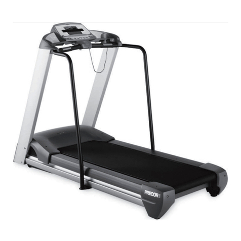
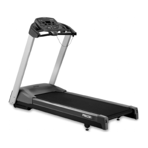
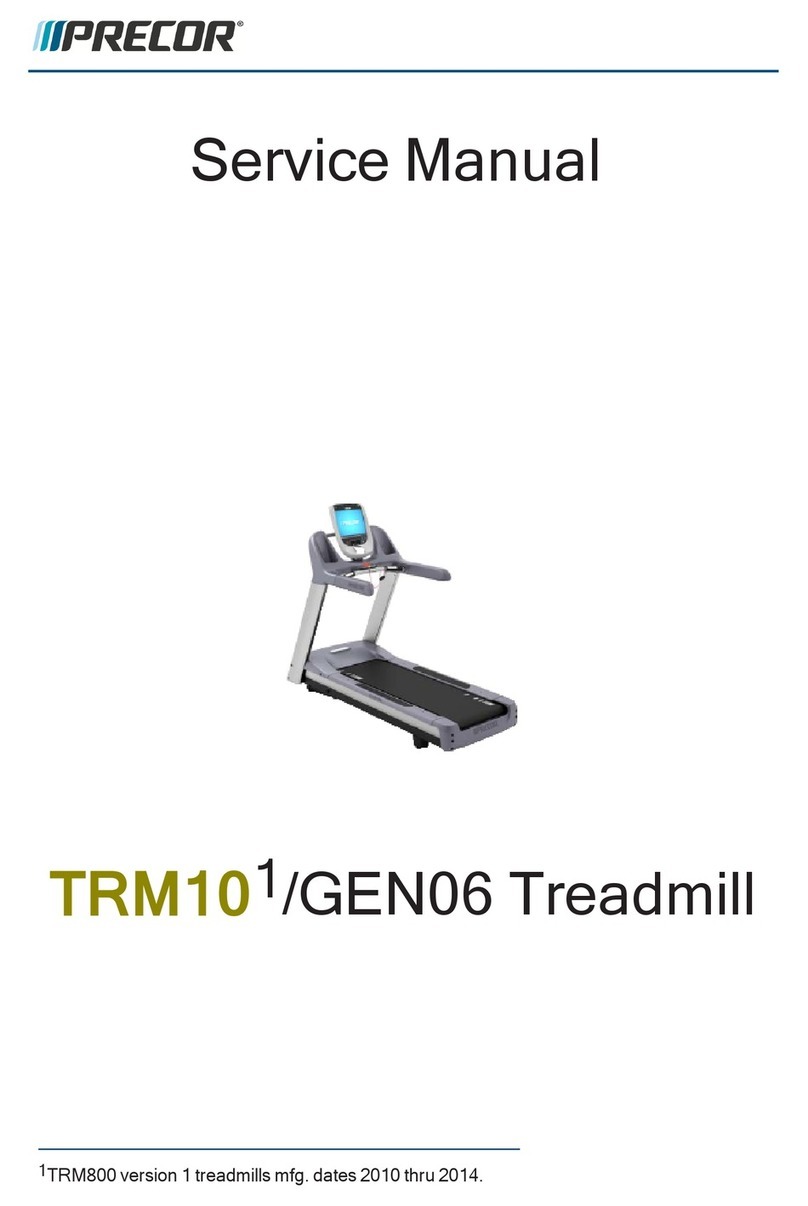
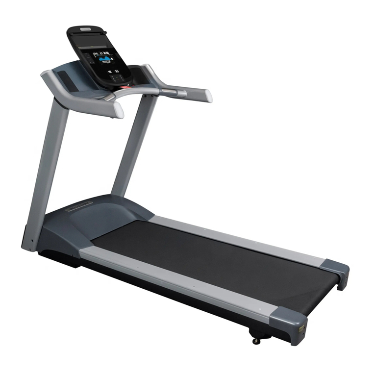
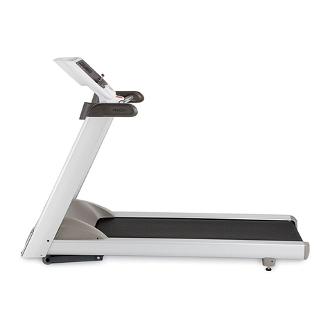
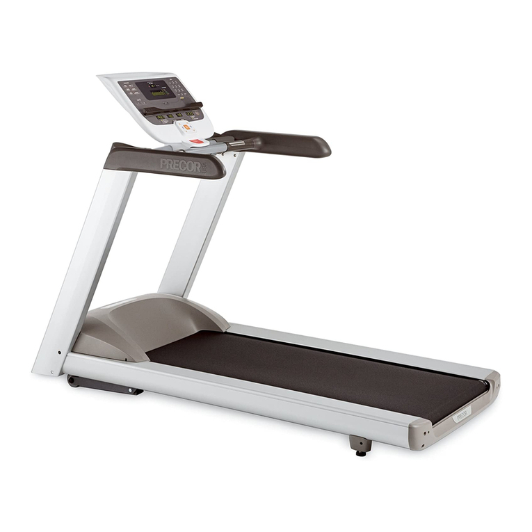
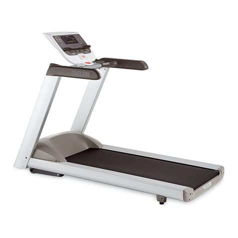
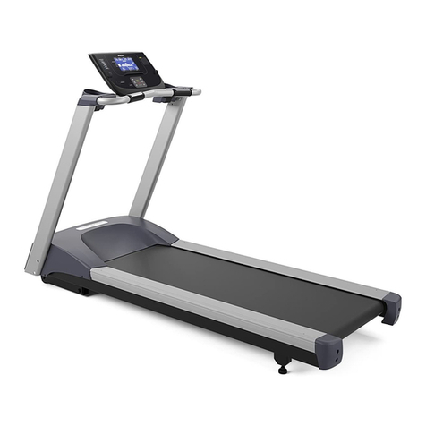
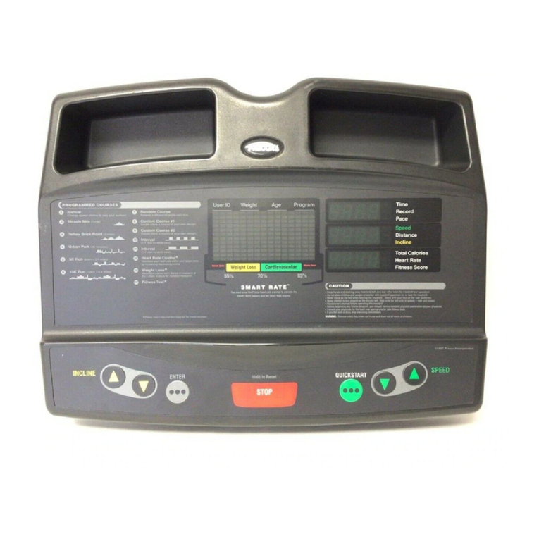
Precor GEN06 Series C952 User manual

Service Manual
TRM10/GEN06 Treadmill
120 VAC and 240 VAC

Contents
1Introduction 1
General Information 3
Orientation 3
Tools 3
Parts 3
Lubrication 4
Cleaning Solutions 4
Electrical Requirements 4
Safety Guidelines 6
Safety guideline you need to know and follow: 6
2Operation Verification 8
Operation Verification Procedure 8
Operation Verification Checklist 9
3Standard Service Software 10
About 10
Service Access Codes 10
Accessing the Service Software 10
Navigating the Service Software Menus 13
Hardware Validation - Diagnostic Tests (51765761) 13
Club Parameter - Settings (5651565) 15
Information Display (65) 18
4Adjustment Procedures 20
Available Adjustment Procedures 20
Drive Belt Tension & Alignment Adjustment 21
About 21
Procedure 21
Lift Motor Calibration 24
About 24
(Undefined variable: TRM700-16Base.ServiceManualTitle) ii

Procedure 24
Running Belt Tension and Tracking Adjustment 26
About 26
Procedure 26
5Replacement Procedures 29
Available Replacement Procedures 29
Auto Stop Magnet Replacement 30
About 30
Procedure 30
Auto Stop Sensor Replacement 32
About 32
Procedure 32
Circuit Breaker Replacement 34
About 34
Procedure 34
Drive Belt Replacement 36
About 36
Procedure 36
Drive Motor Replacement 40
About 40
Procedure 40
Drive Roller Replacement 42
About 42
Procedure 42
End Cap & Belt Guard Cover Replacement 46
About 46
Procedure 46
Incline Lift Motor Replacement 48
About 48
Procedure 48
(Undefined variable: TRM700-16Base.ServiceManualTitle) iii

Incline Lift Platform Replacement 51
About 51
Procedure 51
Input Module Replacement 53
About 53
Procedure 53
Line Filter Replacement 55
About 55
Procedure 55
Power Control Module Replacement 57
About 57
Procedure 57
Power Cord Replacement 59
About 59
Procedure 59
Running Belt and Deck Replacement 61
About 61
Procedure 61
Take Up Roller Replacement 66
About 66
Procedure 66
6Troubleshooting 68
About 68
Introduction to Treadmill Troubleshooting 68
Validate a customer reported issue: 68
Basic Steps 68
Standard Error Codes 70
About 70
Viewing Error Codes 71
Troubleshooting with Error Codes 71
(Undefined variable: TRM700-16Base.ServiceManualTitle) iv

Error Log 73
System Troubleshooting Procedures 74
Available Troubleshooting Procedures 74
Auto Stop Troubleshooting 75
Tripped Circuit Breaker 78
Communications Error Troubleshooting 81
No Power to the Console Troubleshooting 82
Drive Motor System Troubleshooting 83
E-Stop Not Communicating 86
Heart Rate Monitor Troubleshooting 87
Incline System Troubleshooting 89
Input Power and Machine Controls Troubleshooting 90
Running Belt and Deck Troubleshooting 91
Tripped Circuit Breaker 93
7Preventive Maintenance 96
About 96
Maintenance Schedule 96
Running Belt and Deck Cleaning Procedure 99
8Theory of Operation 103
About 103
Consoles 103
Treadmill Base Operation 104
System Diagrams 110
System Block Diagram - 120 VAC 110
System Wiring Diagram 110
9Parts 111
Exploded View Diagram 112
Parts Identification List 117
Appendix A : Edition Information i
Edition i
(Undefined variable: TRM700-16Base.ServiceManualTitle) v

1Introduction
If you are not a Precor certified servicer, you must not attempt to service any Precor Product.
Call your dealer for service information.
WARNING: This service documentation is for use by Precor certified servicer pro-
viders only. Personal injury can result from electrical shock and/or mechanical moving
parts.
This service manual applies to the following treadmill models:
lGEN06 series treadmill: The GEN-06 treadmill base is defined as any treadmill pro-
duced between April 2006 and April 2011. GEN-06 Treadmills include the following
models; C952, C954, C956, and C966.
lTRM10 series treadmill: The TRM10 treadmill base is defined as any treadmill pro-
duced after April 2011 and is configured with a Pxx series console. All of the base and
console combinations are part of the "Experience" line of products.
This document contains information required to perform troubleshooting and replacement pro-
cedures required to repair and maintain this equipment including: general product information,
software diagnostic procedures, preventative maintenance procedures, inspection and adjust-
ment procedures, troubleshooting procedures, replacement procedures and system block and
wiring diagrams.
Separate Base/Console Service Manuals
This document provides information to service the equipment base independent of the
installed console. For console service documentation, refer to the particular console service
manual.
Additional Documentation
There is also an online web version if you have internet access at: Online Service Manual
See Also
"General Information" on page3
"Safety Guidelines" on page6
"Operation Verification" on page8
"Standard Service Software" on page10
"Preventive Maintenance" on page96
"Adjustment Procedures" on page20
"Replacement Procedures" on page29
(Undefined variable: TRM700-16Base.ServiceManualTitle) 1
1 Introduction
General Information
The following information provides general equipment and service information that will help
you to use this manual to properly repair and maintain the treadmill.
Orientation
The equipment orientation (front, right, left, back) used in manual is referenced to a user stand-
ing on the equipment facing the console.
Tools
General set of service and repair tools.
lUS and Metric Hex Key set lStandard and Philips screw driver set
lUS SAE and Metric Wrench set lDVM Multimeter
lTorque wrench lCrank Puller (recommended Park Tool CCP-22)
lUS SAE and Metric socket set lBelt Tension Gauge (recommended Kent-Moore BT-33-73-
F)
lRunning belt tension gauge
(pn PPP00000002000710
Parts
IMPORTANT: Always purchase OEM replacement parts and hardware from Precor.
If you use parts not approved by Precor, you could void the Precor Limited Warranty.
Use of parts not approved by Precor may cause injury.
Exploded View Diagram and Parts List
There is a copy of the parts
Exploded View Diagram
and
Parts Identification List
included in
the "Parts" on page111 chapter that you can use as a quick reference. It is recommended that
you go to the servicer partners Precor Connect (or Precor Connection) website to view the
(Undefined variable: TRM700-16Base.ServiceManualTitle) 3
1 Introduction
General Information

most current parts information including the
Exploded View Diagram
and
Parts Identification
List
.
lPrecor Connect Partner website
Exploded View Diagram and Parts list, see "Parts" on page111.
.
Lubrication
Use only synthetic lubricants such as Mobile 1 Synthetic grease or Super Lube with Teflon.
Use of unapproved lubricants, cleaners, or solvents may void the bike warranty.
CAUTION: Do not apply any lubricants or wax to the deck and belt. Do not use Wax
Blast, silicon sprays, or other applied lubricants. The use of these lubricants will quickly
degrade the low-friction surface of the deck.
CAUTION: Do not use petroleum based lubricants on mechanical components such
as the lift, as this may result in degradation of nylon gearing mechanisms. Use only syn-
thetic lubricants such as "Super Lube with Teflon" or "Mobile One Synthetic" grease
(RED).
Use of unapproved lubricants, cleaners, or solvents may void the treadmill warranty.
Cleaning Solutions
Wipe down equipment with recommended cleaning solution. Use dry cloth to remove residue
solution.
lGeneral: 1 oz. mild soap (Simple Green) to 30 oz. water.
lConsole and PVS: a diluted solution of one part 91% Isopropyl alcohol to one part
water.
CAUTION: Do not use acidic cleaners and do not spray directly onto the equipment
surfaces.
Electrical Requirements
(Undefined variable: TRM700-16Base.ServiceManualTitle) 4
1 Introduction
General Information

Dedicated Branch Circuit
It is required that the treadmill be connected to and operated on a dedicated 20 amp AC
branch circuit. A Dedicated Branch Circuit is defined as a circuit fed by a single circuit breaker
feeding a single load, with a single non-shared neutral providing a return line. A treadmill oper-
ating from a non-dedicated branch circuit or a circuit breaker of less than 20 amps capacity will
not have the necessary power to operate normally under higher load conditions.
120 Vac Systems
120 VAC distribution systems utilize a single pole circuit breaker (power lead) and a neutral
lead connected to a common neutral (ground) bar. The AC. safety ground (green wire) is con-
nected to a separate ground bar in the distribution system.
If it is determined that any of the above electrical conditions are in question, please consult with
a qualified electrician to make appropriate circuit changes.
CAUTION: The treadmill requires a 20-amp individual branch circuit grounded per
NEC (National Electric Code) guidelines or local region electric code.
IMPORTANT: If the AC circuit feeding a treadmill is found to be a non-dedicated
branch circuit or a circuit equipped with a capacity of less than 20 amps, the AC circuit
must be corrected before any reliable Troubleshooting can be performed. More
importantly, a non-dedicated branch circuit may constitute a safety hazard to the tread-
mill operator .
Input Power
Nominal 120 VAC models
lOperating voltage: 90 VAC to 132 VAC.
lFrequency: 47 65 Hz
Nominal 240 AC Models
lRated Operating voltage: 180 VAC - 264 VAC.
NOTE: An Internal operating voltage range of 180 – 275 VAC with reduced per-
formance is allowed.
lFrequency: 47-65 Hz
Frame Ground
For operator safety and to minimize electrostatic discharge conditions the AC frame ground
continuity must also be verified to be a low resistance connection to the AC distribution ground
bar.
(Undefined variable: TRM700-16Base.ServiceManualTitle) 5
1 Introduction
General Information

Safety Guidelines
WARNING: Only Precor certified servicers and technicians are permitted to service
Precor products. Personal injury can result from electrical shock and/or mechanical
moving parts.
Safety guideline you need to know and follow:
lRead and follow all Warning notices to protect yourself from personal injury.
lRead and follow all Caution notices to prevent damage to the equipment.
lRead the owner’s manual and follow all operating instructions.
lOperate the equipment on a solid, level surface.
lVisually check the equipment before beginning service or maintenance operations. If it
is not completely assembled or is damaged in anyway, do not attempt to operate the
equipment.
lNever place liquids on any part of the equipment while performing service.
lTo prevent electrical shock, keep all electrical components away from water and other
liquids.
lDo not use accessory attachments that are not recommended by the manufacturer.
Non-OEM accessories can cause injuries.
lDo not stand or climb on the handlebars, display enclosure or cover.
lOn a self-powered unit, it will either be necessary to either equip the unit with the
optional external power supply or have an assistant pedal on the unit while voltage
measurements are being taken. Because of the danger of working on the unit while it is
in motion using the optional external power supply is strongly recommended.
lOn ATM units when the stairarms are in motion; the generator will operate and produce
potentially hazardous voltages even when the battery is disconnected.
lOn AMT units with Cardio Theater PVS units will have external power supply and
coaxial cable routed through the bottom of the unit to the top of the display console.
Cord management must be maintained
lOn ATM units, a pinching hazard exists when the unit is operated. It is possible to ser-
iously pinch a finger. The AMT can be mechanically locked by inserting a screwdriver
through the primary sheave and frame.
lOn treadmills, removing the hood exposes high voltage components and potentially dan-
gerous machinery. Exercise extreme caution when you perform maintenance pro-
cedures with the hood removed.
When servicing the equipment:
lDuring service operations you will be very close to moving machinery and voltage bear-
ing components:
oRemove jewelry (especially from ears and neck),
oTie up long hair,
(Undefined variable: TRM700-16Base.ServiceManualTitle) 6
1 Introduction
Safety Guidelines

2Operation Verification
This section provides a method of verifying the TRM10/GEN06 Treadmill Base operation.
Check the treadmill operation at the end of a maintenance procedure and when it is necessary
to ensure that the treadmill is operating properly.
"Operation Verification Procedure" below
"Operation Verification Checklist" on the facing page
Operation Verification Procedure
Perform these tests to verify operation of the unit.
1. Plug the power cord into the wall outlet and switch the power switch to the "ON" pos-
ition.
2. Press and hold the RESET key for a minimum of 6 seconds, if errors are logged, the
error log will be displayed. Make note of all logged error codes and odometer reading.
The odometer reading can help you determine the age and relevance of the error.
Note that on P80 consoles, go to the error event log to view logged errors, see "Access-
ing the Service Software" on page10.
3. Clear the error log; select a logged error and then hold down the QUICK START key
until the error is deleted.
4. Enter the Hardware Validation Test by entering access code 5,1,7,6,5,7,6,1:
a. Press either the STOP,PAUSE or RESET buttons and then enter
5,1,7,6,5,7,6,1
Note: For P80 consoles, refer to "Accessing the Service Software" on page10.
5. Select and run the Display Test, the Keypad Test, and the Heart Rate Test, Verify that
each test is successfully completed with the following results:
lLEDs light
lKeys all function
lHeart rate is acquired and displayed
6. Enter the Machine Tests submenu and run the Belt Speed Test and the Incline Test.
Verify following results:
lRunning belt operates from minimum to maximum speed.
lIncline moves up and down and the A/D value is approximately 6000+/-500 at 0%
incline.
7. Press the RESET key to exit diagnostics. On P80 consoles, press Back to exit dia-
gnostic and return to the Home page.
8. Operate the unit in the Manual program. Adjust the speed of the running belt to 2–3
mph. Operate the treadmill for at least 5 minutes while walking on the unit.
(Undefined variable: TRM700-16Base.ServiceManualTitle) 8
2 Operation Verification
Operation Verification Procedure

9. Concentrate on the feel of the running belt, the sound of the drive motor and rollers. Be
on the alert for unusual noises, smells or vibrations.
10. Observe the LED’s on the console. Make sure that each LED lights as the information
corresponding to that LED is displayed on the console.
11. Press the INCLINE UP key while viewing the console. Confirm that the running deck
inclines and the incline indicator increments to 15% as the INCLINE UP key is con-
tinually pressed.
12. Press the INCLINE DOWN key while viewing the console. Confirm that the running
deck returns to a level position and the incline indicator decrements to 0% as the
INCLINE DOWN key is pressed. (Depending on the software configuration of the con-
sole, the lowest level of incline can be either 0% or -3%).
13. While the running belt is in motion, press the STOP button and verify the running belt
stops.
14. Restart the running belt and while the running belt is in motion, pull the ESTOP cord
and verify the running belt stops.
15. Press and hold the RESET key for a minimum of 6 seconds and view the error log
again. This time check for any NEW error codes that may have resulted from the veri-
fication tests. Repair any new error codes and repeat the verification tests.
Note that on P80 consoles, go to the Event Log page to view logged errors, see
"Accessing the Service Software" on page10.
Operation Verification Checklist
Use this checklist to track that the verification procedure tests were successfully completed
and that the treadmill operation has been verified:
Check, record, and then clear any errors in the error log.
Verify that all LEDs function properly during the Hardware Validation tests.
Verify that all keys on the keypad function properly during the Hardware Val-
idation tests.
Verify that the heart rate functions normally and displays a valid heart rate.
Verify the running belt drive system functions properly throughout the minimum
to maximum range of control. All drive system components (deck, belts, rollers,
IFT) are free of excessive noise, vibrations, or smells.
Verify the Incline A/D value is approximately 6000+/-500 at 0% incline, the
incline operates within the complete range of the lift when the UP or DOWN
keys are pressed and is free of excessive noise or vibrations.
Verify the STOP button stops the running belt from moving.
Verify that pulling the ESTOP cord stops the running belt from moving.
Check for any new error codes that may have been logged in the error log during
operation verification of the treadmill.
.
(Undefined variable: TRM700-16Base.ServiceManualTitle) 9
2 Operation Verification
Operation Verification Checklist

3Standard Service Software
About
Standard access codes are used across Precor cardio product lines to access a set of com-
mon service software functional modes used to retrieve equipment product and usage inform-
ation, manage club settings, and hardware maintenance validation/diagnostic test software.
Each mode is assigned a unique service access code that is entered into the console to begin
the functional mode. There are three functional modes: Hardware Validation, Club Para-
meters, and Information Display:
lHardware Validation is a set of functional diagnostic tests used to troubleshoot and
verify proper operation.
lClub Parameters also referred to as Club Settings are used manage and configure the
usage of the machine.
lInformation Display provides information about the equipment usage, hardware, soft-
ware, and error log data.
The user interface, available information, settings, etc. will vary based on the console model -
base configuration. Make sure to use the information and instructions for your particular con-
sole application. Consoles that support standard service access codes include:
• Standard Consoles • P30 console
• P10 consoles • P80 console
• P20 console
Service Access Codes
The following table lists the standard service access codes and associated functional mode.
SERVICE
ACCESS CODE SERVICE MODE FUNCTION
5,1,7,6,5,7,6,1 Hardware Validation Diagnostic tests.
5,6,5,1,5,6,5 Club Parameters Configure machine and workout
parameter limits.
6,5 ‡Information Display‡View usage, SW, and Error Log
information.
Note: ‡Access code 65 not used on the P80, use access code 51765761.
Accessing the Service Software
The process to access the service code functional mode varies between console models. Go
to instructions listed below for your particular console to learn how to access the service
(Undefined variable: TRM700-16Base.ServiceManualTitle) 10
3 Standard Service Software
About

software.
Standard, P10, and P30 Consoles
To access the service software:
lPress either the STOP,PAUSE, or RESET key.
lSequentially type in the service access code using the numeric keypad.
NOTE: The access code must be correctly and quickly entered or the process will
abort. Restart the process from the beginning if this occurs.
P20 Consoles
To access the service software:
(Undefined variable: TRM700-16Base.ServiceManualTitle) 11
3 Standard Service Software
Accessing the Service Software

lPress either the STOP,PAUSE, or RESET key.
lSequentially type in the service access code using the following control keys to rep-
resent an equivalent numeric value:
1=Workouts key
5=Enter key
6=Up key
7=Down key
NOTE: The access code must be correctly and quickly entered or the process will
abort. Restart the process from the beginning if this occurs.
P80 Consoles
To access the service software:
lMake sure the P80 is set to the Welcome home page.
lPress and continue holding down the PAUSE key while pressing the Volume and
Channel Up/Down keys in the following sequence ("X" pattern) to open the service soft-
ware login page:
Press/hold PAUSE while selecting CH Up >Vol Down >Vol Up >CH Down
NOTE: Keep the keypad entry interval to greater than 1 second between
key presses. Key press interval speed faster than 1 second may result in an
unsuccessful login. .
lSuccessful login will open the service access login page. Use the touch-screen keypad
to type in the service access code > Continue to open the functional mode software.
(Undefined variable: TRM700-16Base.ServiceManualTitle) 12
3 Standard Service Software
Accessing the Service Software

oTo access the Hardware Validation (5,1,7,6,5,7,6,1) diagnostic test page:
Select System Settings (
Settings
page) >System Test (
System Settings
page)
>opens
Diagnostic tests and hardware calibration
page.
Navigating the Service Software Menus
Console hardkeys and softkeys used to navigate the service software menus.
Standard, P10, P20, & P30 consoles:
The service software is organized in a sequential top-menu sub-menu architecture with instruc-
tions shown on the workout information display. Use the console keys to navigate and select
service mode operations.
CONSOLE KEY FUNCTION/DESCRIPTION
Up/Down Moves up and down through the current menu.
OK Selects current menu item or confirms setting.
BACK/CLEAR • Returns to the previous menu level without saving changes.
• Hold Back to exit the Display test.
PAUSE • Exits service mode
• Press and hold PAUSE will open the Error Log or show the "Stuck
Key" message when there are no logged errors.
P80 series consoles:
The P80 uses the touch-screen to view, navigate, and perform the diagnostic tests. Follow on-
screen prompts to access and complete tests.
Hardware Validation - Diagnostic Tests (51765761)
Service Access Code: 5,1,7,6,5,7,6,1 (see "Service Access Codes" on page10)
The set of available diagnostic tests will vary based on console model. Select console model to
view the available diagnostic tests.
Standard, P10, P20, & P30 consoles:
DIAGNOSTIC
TEST TEST DESCRIPTION
Display Test Tests the console LEDs. Successively press the OK key to verify each group
of LEDs and verify that all LED's illuminate. Press Back to exit the test.
Keypad Test An illuminated LED map of the function keys will be shown. Press each indi-
vidual key and verify that the corresponding LED extinguishes. Press and hold
BACK to exit the test
PVS Key Test Not used, OEM test.
Heart Rate Test Tests the unfiltered, filtered, and pulse values. Grasp the grips to test the hand
held heart rate. Use a Polar heart rate simulator to test the wireless heart rate.
(Undefined variable: TRM700-16Base.ServiceManualTitle) 13
3 Standard Service Software
Navigating the Service Software Menus

DIAGNOSTIC
TEST TEST DESCRIPTION
Press the back button to exit this test.
Belt Test Tests the belt speed in 0.1 mph increments showing the required Input
Voltage,Input Current to the treadmill, the Output Voltage, and Drive
Motor current at each speed.
Auto Stop Test Tests the Auto Stop function showing the averaged foot plants and exerciser
"is detected"/ "is not detected" function. Foot plant averaging delay resets
with each speed change.
Incline Test Tests the incline &Decline function. Allows you to verify the A/D number at
any incline level and the number of Glitches (communication time between
the LPCA and UPCA).
Stop Key TestTests the Stop Key function for P10 and P30 console s.
Test procedure prompts to press the Stop Button, then disconnect and recon-
nect the Lanyard E-Stop, and then press Stop to reset and exit the test.
P80 Series Consoles:
On P80 consoles, Diagnostic Tests are located on the Diagnostic tests and hardware cal-
ibration page:
lAccess code 51765761
lselect System Settings
lSelect System Tests
lOpens Diagnostic tests and hardware calibration page, select test from menu.
DIAGNOSTIC
TEST TEST DESCRIPTION
Auto Stop Test Tests the Auto Stop function showing the averaged foot plants and exerciser
"is detected"/ "is not detected" function. Foot plant averaging delay resets
with each speed change.
Belt Speed Test Tests the belt speed by stepping the speed in 0.1 mph increments and show-
ing the required drive motor current.
Incline Test Tests the incline &Decline function. Allows you to verify the A/D number at
any incline level and the number of Glitches (communication time between
the LPCA and UPCA).
USB Test Shows detected USB devices.
Touchscreen Test Use finger to draw line across touch-screen. Select Finish to exit.
Touchscreen Cal-
ibration
Touch the cross points on the touch screed to proceed through the calibration
procedure.
Backlight Test Tests the console LEDs. Successively press the OK key to verify each group
of LEDs and verify that all LED's illuminate. Press Back to exit the test.
RGB Test Test the touch-screen RGB colors. Touch screen to advance through the red,
green, blue, and white colors.
Speaker Test Tests speakers.
(Undefined variable: TRM700-16Base.ServiceManualTitle) 14
3 Standard Service Software
Hardware Validation - Diagnostic Tests (51765761)
This manual suits for next models
4
Table of contents
Other Precor Treadmill manuals

Precor
Precor 9.21 User manual

Precor
Precor 905e User manual

Precor
Precor C966 User manual

Precor
Precor 9.35 User manual

Precor
Precor M9.45 User manual

Precor
Precor 9.33 User manual

Precor
Precor 9.35 Owner's manual

Precor
Precor 9.31 Owner's manual

Precor
Precor Experience Series 700 Line User manual

Precor
Precor C954 User manual

Precor
Precor C954 User manual

Precor
Precor M9.25i User manual

Precor
Precor TRM 800 Assembly Instructions

Precor
Precor C954i User manual

Precor
Precor Treadmill EFX534 User manual

Precor
Precor M9.41si User manual

Precor
Precor C936i User manual

Precor
Precor M9.45 User manual

Precor
Precor Move Beyond 966i Owner's manual

Precor
Precor 9.45 User manual