PrefecTron ROC235A User manual

Safety information
Electrical safety
Operation safety
Statement

Revision History
1. - -
2.
Packing list
□-
□
-
-
-
If any of the above items is damaged or missing, please contact your local distributor.
Ordering information
Model Number
Description
-
-
-
-
-
-
-
-
-

Table of Contents
SAFETY INFORMATION.............................................................................................................................................1
..............................................................................................................................................................
..............................................................................................................................................................
........................................................................................................................................................................
REVISION HISTORY...................................................................................................................................................2
PACKING LIST ...........................................................................................................................................................2
ORDERING INFORMATION .......................................................................................................................................2
TABLE OF CONTENTS................................................................................................................................................3
CHAPTER 1: PRODUCT INTRODUCTION....................................................................................................................5
..............................................................................................................................................................
...........................................................................................................................................
.............................................................................................................................................
.............................................................................................................................................
CHAPTER 2: JUMPERS AND CONNECTORS................................................................................................................8
......................................................................................................................
.......................................................................................................................................................
........................................................................................................................................................
2.2 Rear Panel Connector Pin Definitions.................................................................................................................
................................................................................................
................................................................................................
--........................................................................................................................................
--..............................................................................................................................................................
.................................................................................................................................................................
............................................................................................................................................................
...................................................................................................
..........................................................................................................................
................................................................................................................................................
..................................................................................................................
..................................................................................................................
.................................................................................................................
....................................................................................................................................................................
CHAPTER 3: SYSTEM SETUP....................................................................................................................................14
..............................................................................................................................
......................................................................................................................................................
...................................................................................................................................
........................................................................................................................................
..............................................................................................................................
CHAPTER 4: AMI BIOS UTILITY ...............................................................................................................................22
...................................................................................................................................................................
.......................................................................................................................................................
..............................................................................................................................................................
.......................................................................................................................................................
...................................................................................................................................................
..........................................................................................................................................
.........................................................................................................................................

...................................................................................................................................
...................................................................................................................
...........................................................................................................................
.............................................................................................................................
-....................................................................................................................................
- .....................................................................................................
.........................................................................................................................................
........................................................................................................................................
....................................................................................................................
...................................................................................................................................
....................................................................................................................
................................................................................................................................
.....................................................................................................................................................................
- .....................................................................................................................................
.......................................................................................................................................
.............................................................................................................................
....................................................................................................................
................................................................................................................................
................................................................................................................................
............................................................................................................................................................
...................................................................................................................................................................
............................................................................................................................................................

Chapter 1: Product Introduction
1.1 Key Features
-
-
-
2 x 204-pin SO-DIMM DDR3 1333/1600 MHz up to 16 GB
2 x PCI
1 x Mini PCIe
2 x 2.5" HDD/SSD
-
--
-
--
-
-
-
-
-
-
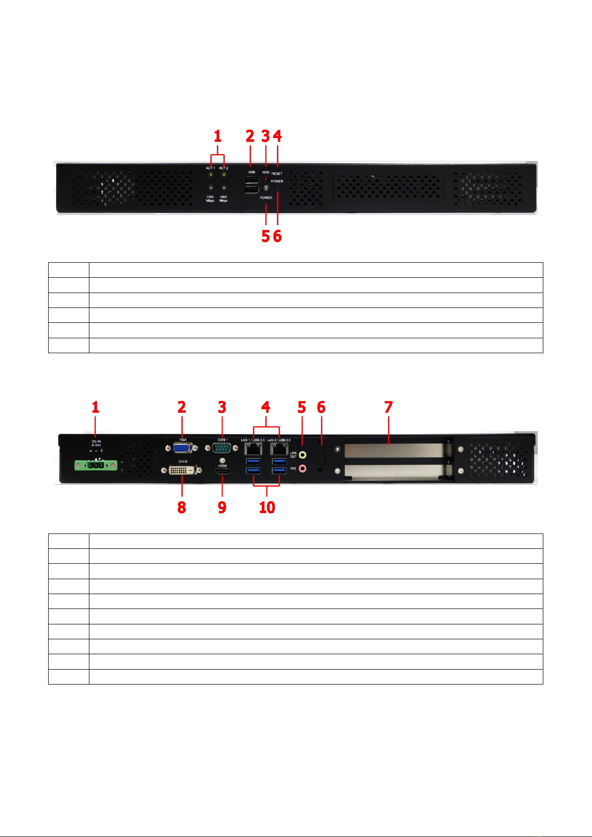
1.2 Front Panel Components
1.3 Rear Panel Components
-
--
--
-
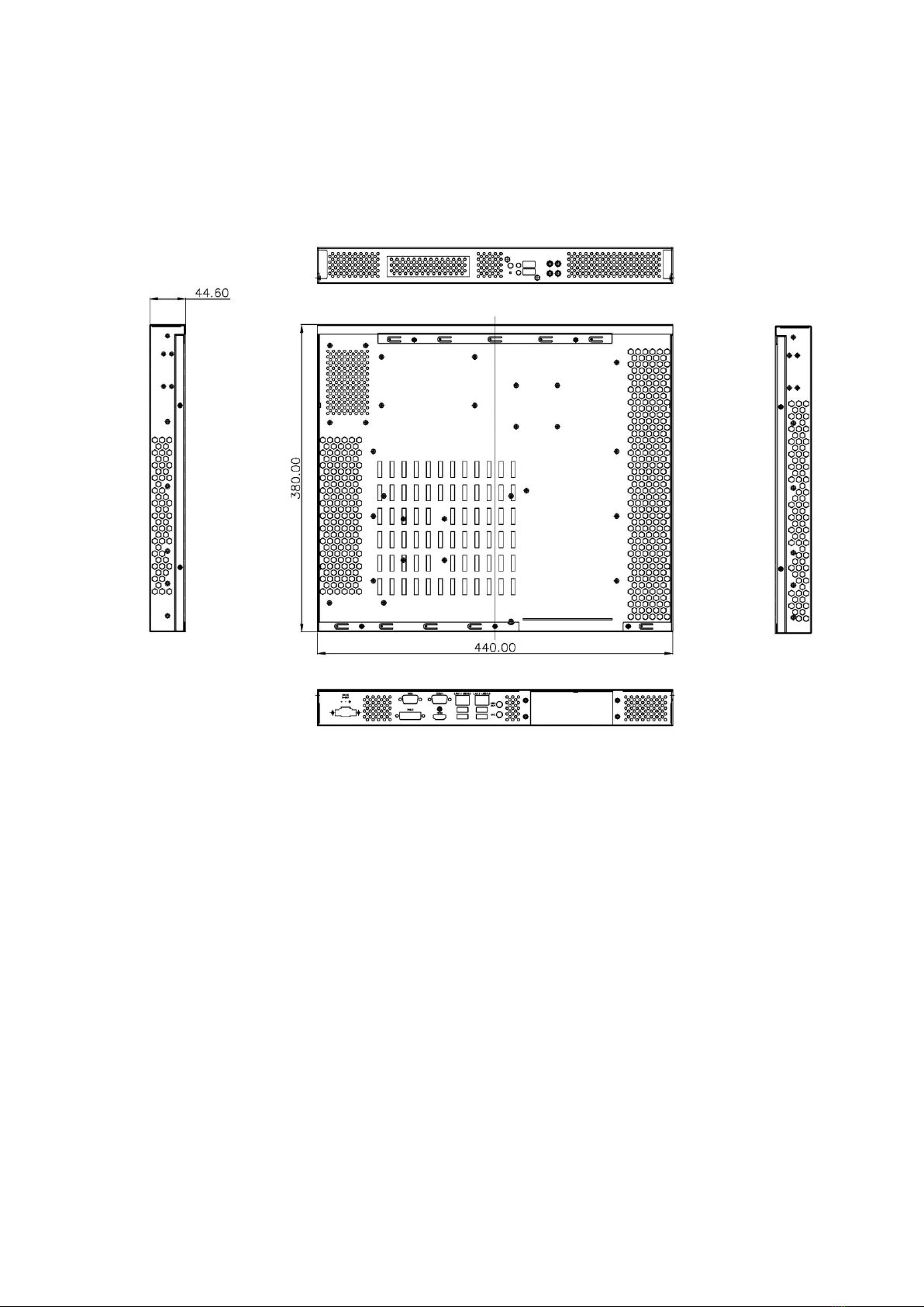
1.4 Mechanical Dimensions
Chapter 2: Jumpers and Connectors
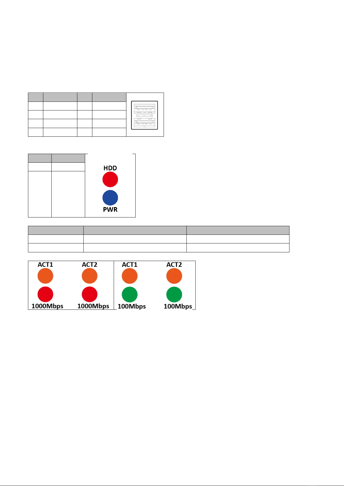
2.1 Front Panel Connector Pin Definitions
USB Port: USB2.0
-
-
Status Indicators
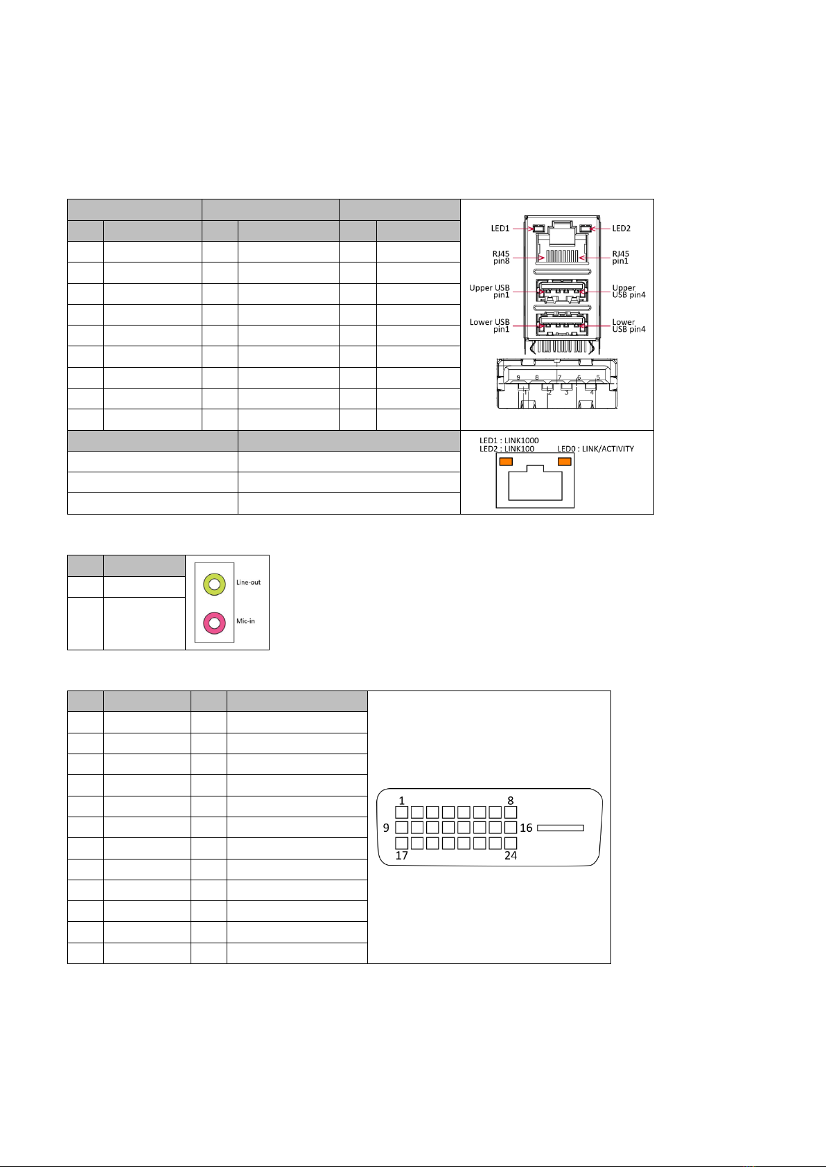
2.2 Rear Panel Connector Pin Definitions
LAN1_USB12: USB3.0 port 0,1 and LAN connector 1
LAN2_USB34: USB3.0 port 3,4 and LAN connector 2
-
-
-
-
-
-
-
-
-
-
-
-
AUDIO1: LINE-OUT/MIC-IN
-
-
DVI-D: DVI-D
-
-
-
-
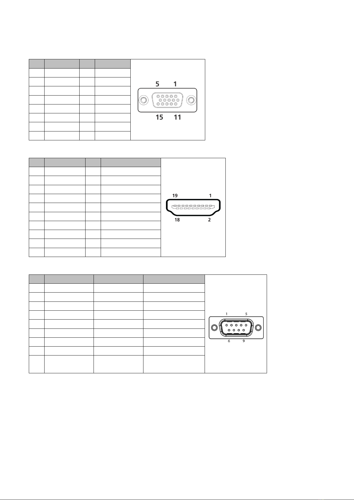
VGA: VGA
HDMI: HDMI
COM1: RS232/422/485 with +12V/+5V selection
-
-
-
-
-
-
-
-
-
-
-
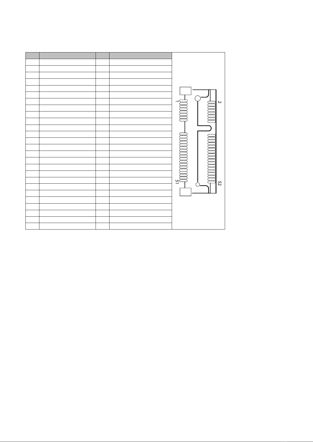
MINI_MPCIE: Mini PCIe connector
-
-
2.3 Internal Connectors
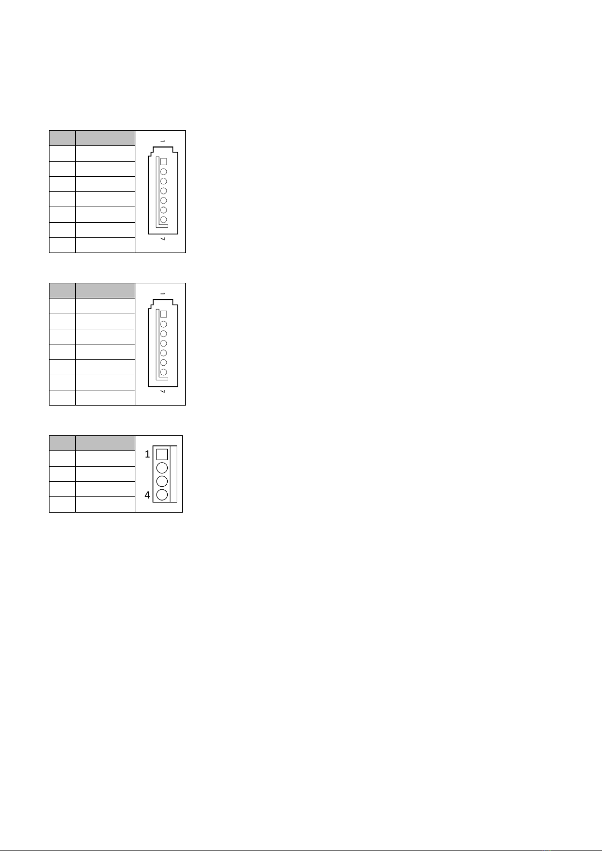
SATA1, SATA2: Serial ATA 3.0 Connector
SATA3, SATA4: Serial ATA 2.0 Connector
SATAP0, SATAP1: SATA Power Connector

PCI: PCI
-

Chapter 3: System Setup
Prior to removing the chassis cover, make sure the unit’s power is off and disconnected
from the power sources to prevent electric shock or system damage.
3.1 2.5" SATA HDD/SSD installation
1.

2.
3.
4.

3.2 CPU installation
-
-
-
1.
2.
3.

4.
5.
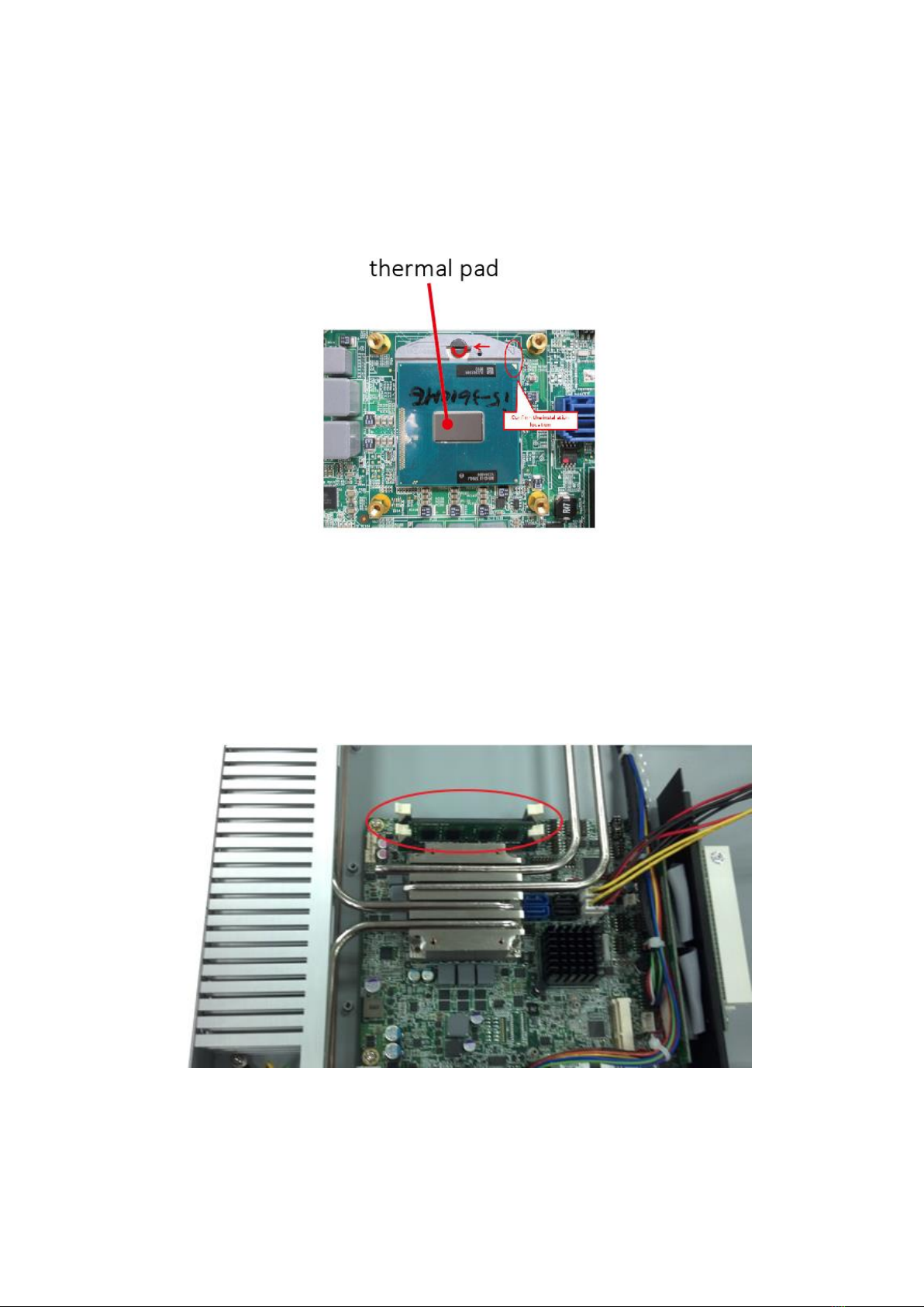
6.
3.3 Memory module installation
--
1.
2.

3.4 PCI riser card installation
1.
2. -
3. -
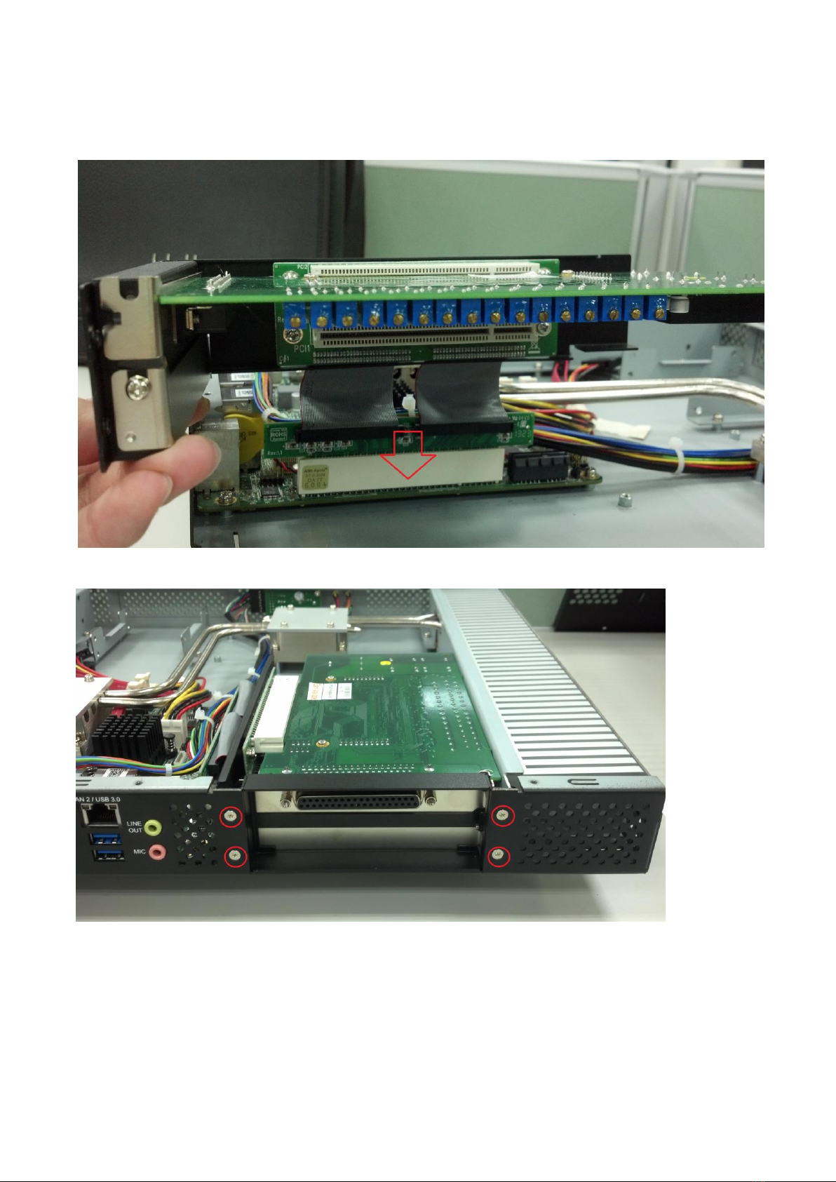
4. --
5.
This manual suits for next models
2
Table of contents


