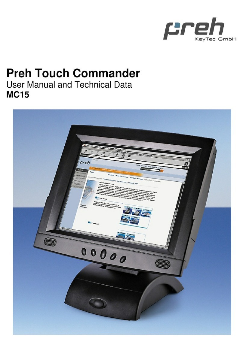
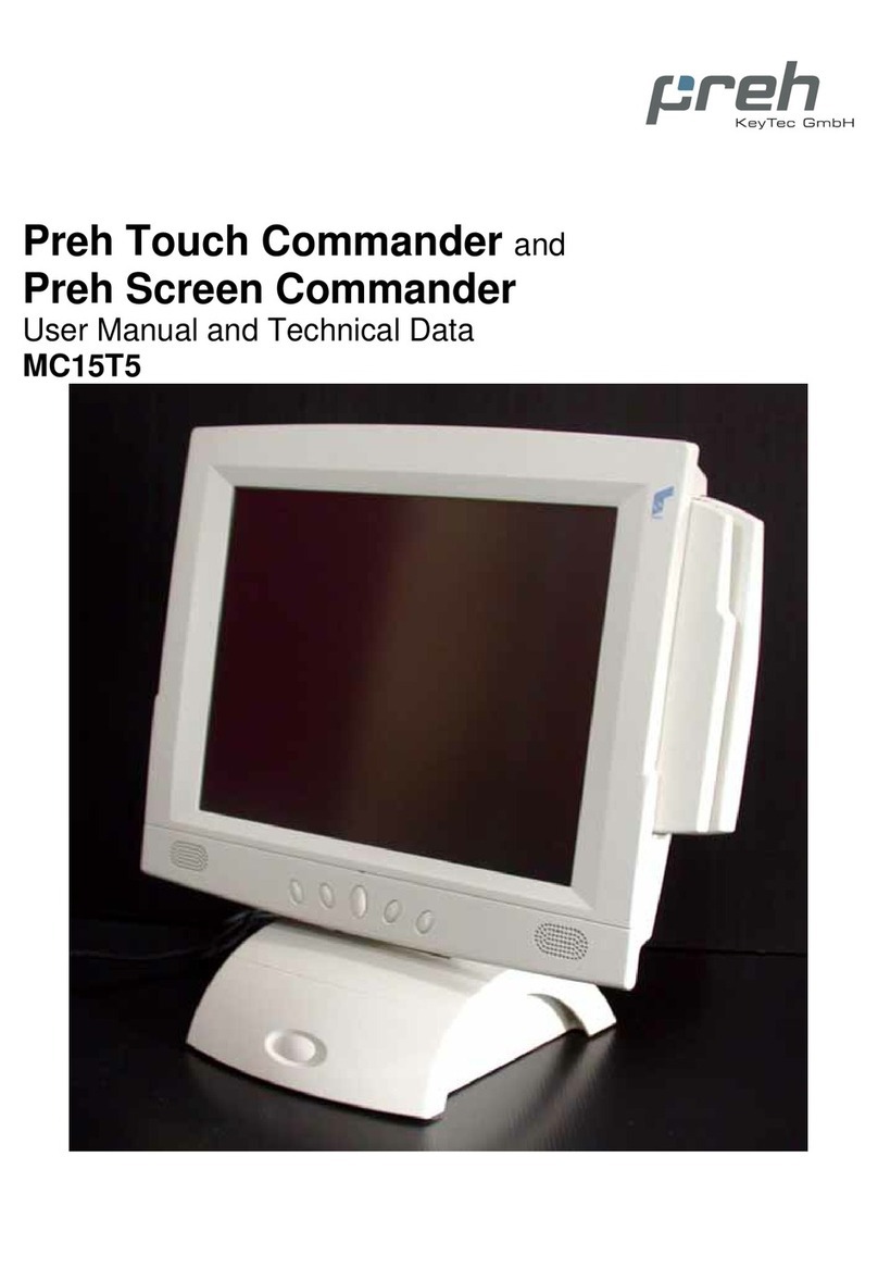
Preh MC12T3 User manual

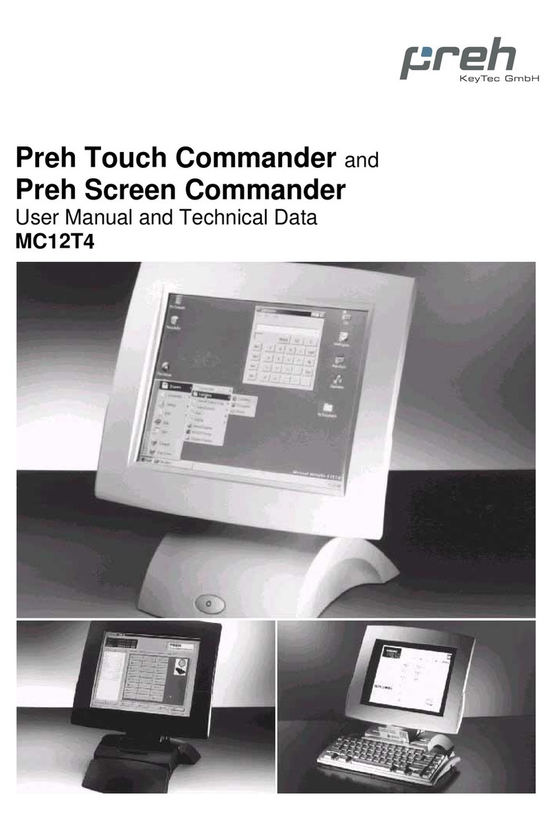
Preh Touch Commander
Preh Screen Commander
Operators Manual and Technical Data

2
Table of Contents
1General Points__________________________________________________________ 6
2Contents of packing______________________________________________________ 7
3Installation of Touchscreen _______________________________________________ 8
3.1 Conditions for the System _______________________________________________ 8
3.2 Cable Installation and System Settings _____________________________________ 8
3.3 On Screen Display (OSD)_______________________________________________ 9
3.3.1 Menu: BASIC SETTINGS ___________________________________________________ 10
3.3.2 Menu: IMAGE POSITION ___________________________________________________ 11
3.3.3 Menu: SYSTEM___________________________________________________________ 12
3.4 Mechanical Adjustment of the LCD Position________________________________ 13
4Driver Installation______________________________________________________ 14
4.1 Driver for resistive Touchscreens ________________________________________ 14
4.2 Driver for capacitive Touchscreens ______________________________________ 14
5 Care _________________________________________________________________ 15
6Troubleshooting _______________________________________________________ 15
6.1 General Points ______________________________________________________ 15
6.2 Diagnostic Programme ________________________________________________ 15
6.3 Troubleshooting list __________________________________________________ 16
6.4 Additional help ______________________________________________________ 17
7Technical Data ________________________________________________________ 17
8Safety Instructions______________________________________________________ 19
9Further Indications_____________________________________________________ 19
10 Warranty _____________________________________________________________ 19
11 Statement of Confirmation_______________________________________________ 20
12 FCC Warning Statement ________________________________________________ 20

3
Model with integrated
power supply in the foot
Pict. 1: front view
Pict. 2: rear view
Pict. 3: view from below
VGA connector
supply voltage
connector (main power)
serial connector RS 232
(touch controller)
Inbus key
audio cable (with models
with loudspeaker only)
LED
Exit key
Up key
Down key
Select key
swing direction
Volume regulator (with models
with loudspeaker only)
LC-Display (12,1”)
with touch interface
or monitor glass
ON/OFF switch
loudspeaker
(optional)
swing direction

4
Model with
Modular foot
Pict. 4: front view
Pict. 5: rear view
Pict. 6: view from below
VGA Connector
Power Supply
Serial Connector RS 232
(Touch Controller)
Inbus Key
LED
Exit Button
Up Button
Down Button
Select Button
Swing Direction
LC-Display (12,1”)
with touch interface
or monitor glass
Base Cover Module
Magnetic
Card Reader
(Optional)
Smart Card
Reader (Optional)
Swing Direction

5
LC-Display (12,1”) with
touch surface or
monitor glass
VGA connector
(15 pol.)
Power Supply
(jack bush)
serial connector RS 232
(Touch Controller)
Model with bracketry
for pole or wall mount
Pict. 7: front view
Pict. 8: rear view I
Pict. 9: rear view II (bracketry)
LED
Exit Button
Up Button
Down Button
Select Button
Bracketry
Threaded bushings
(M5)

6
1General Points
The Preh Touch Commander serves as graphical input device which makes the screen
of the computer react immediately on touching graphical operating characters (symbols,
keys, printings etc.). In this way touchscreen allows simple, interactive handling of a
computer even for the PC-inexperienced user. For example this input media offers the
possibility of reducing training time and costs for the operating staff via a comfortable
user's dialogue. With its ergonomic design and its comfort in handling the Preh Touch
Commander is applicable in the fields of medicine, commerce, gastronomy, fast-food
as well in the restaurants and hotel business.
The Preh Touch Commander consists of two logical units, the active matrix color LDC
(TFT) and the highly sensitive touch. These two units must be considered different from
each other in regard to their function. This means that the appearance of the picture on
the LCD (screen) is to be considered independent on the touch drivers. As far as the
computer is concerned the system is connected with the VGA output (LCD) as well as
with a serial interface (touching function).
The Touch Commander can thus take over the function of monitor and mouse.
A normal mouse can be used parallel to the Touch Commander.
The Preh Screen Commander is without a touch surface. Instead of this you will have a
monitor glass. In this case you do not have a touch function on the screen. You will have
a high quality TFT monitor.
The active matrix Color LCD (TFT) has a diagonal of 12,1" (307 mm) with a resolution of
800x600 image spots as well as 262.144 colours. The display has an especially high
degree of brightness (type.250 cd/m²) and colour brilliancy as well as a large viewing
angle of 110° horizontally and 85° vertically. The LCD parameters as for example
brightness, contrast, picture position etc. are adjustable via the On Screen Display
(OSD).
The analogous resistive 5 wire touch technology has a resolution of 1.024x1.024
spots. Giving in data is done by touching it with a finger or a blunt object. The strength of
resolution thereby corresponds with 1N. The touch surface consists of a hardened
polyester foil with a high resistance against scratches and an insensitivity to dirt, fat and
water splashes. The durability amounts to about 35 million single actuation per touching
point.
The capacitive touch technology has also a resolution of 1.024x1.024 spots. Giving in
data is done by touching it with a finger. The touch needes no force. As the System is
processing with capacitive changes, it is not possible to use isolated parts (gloves, pen
...) for making an input. The touch surface consists of a hardcoated glass with a high
light transmission, resistance against scratches and an insensitivity to dirt, fat and water
splashes. The durability amounts to about 20 million single actuation per touching point.
Models with loudspeakers (optional) allow the possibility of giving the user a feedback
via sounds and noises. The volume can be regulated by a tuner on the rear side of the
foot.

7
The Preh Touch Commander/Preh Screen Commander with modular foot enables the
simple swapping of the base cover modules in exchange for an independently-
programmable MC 80 W/X-, MC 84 W/X- or MC 128 W/X-keyboard. The optional
integration of a magnetic- and/or Smart Card reader into the cover module is provided
for.
The Preh Touch Commander/Preh Screen Commander can also be used with optional
bracketry for wall mount or pole mount hardware.
Pict. 10: Example for adjustable Pict. 11: Example for adjustable
Wall mount solution telescope pedestal (pole mount)
2Contents of packing
Prior to taking into operation your touchscreen/TFT monitor, please check whether the
following single parts are there and in undamaged condition:
1Touchscreen Preh Touch Commander or TFT monitor Preh Screen Commander
1CD-Rom with touchscreen driver for the operating systems DOS, Windows
3,1x/9x/NT/2000 and OS/2.
1Operator's Manual
1VGA cable
1serial cable (not included at Screen Commander)
1power cable
For the models with the modular foot or the bracketry version there must be a power
supply (12 V, 2 A) included.

8
3Installation of Touchscreen
Please read the following indications prior to starting work with the Preh Touch
Commander/Preh Screen Commander!
The following steps are necessary for a correct function of the device:
1Adjust computer and switch it off, connect Touch Commander/Screen Commander,
switch on computer and Touch Commander/Screen Commander (see chapter 3.2).
2Adjust displays for graphic card in the computer by means of menu point "AUTO-
ADJUST" of the OSD. This step is important for the quality of representation (see
chapters 3.3).
3Only Touch Commander:
Installation of touchscreen driver for the corresponding operating system (see
chapter 3.5).
The Touch Commander/Screen Commander with the modular foot or bracketry must be
operated with the delievered original power supply.
3.1 Conditions for the System
The Preh Touch Commander/Screen Commander has been developed for the use on
PC graphic adapters in SVGA-setting with 800x600 spots of resolution. As an operating
system it is necessary to have either a DOS version 3.3 (or higher), Windows 3.1x,
Windows 9x, Windows NT, Windows 2000 or OS/2.
For models with loudspeakers a sound card with "Line Out" outputs for generating
sounds is necessary in addition.
3.2 Cable Installation and System Settings
The installation of the cables must be done with the computer switched off. The best
thing to do is to set the correct screen resolution first (in Windows 3.1x/9x/NT and OS/2.
The optimum resolution is 800x600 image spots, however, you can also use a resolution
of 640x480.With Windows 9x you should take the Laptop-Monitor 800x600 out
of the standard monitor types (refresh rate 60 Hz).
To start with connect the VGA cable and the RS232 cable as well as the audio cable
(with loudspeaker models only) (see pict. 3 and pict. 6). Then plug in the mains
connection cable to the socket (see pict. 3).
If you now switch on the computer, the LED lights up green after about 3 seconds and
the corresponding picture appears on the screen. If the computer is in suspend or
standby mode the LED is off.

9
Firmware Version
Status Display
If the SVGA cable between touchscreen/TFT monitor and computer is disconnected, the
LED lights up red.
3.3 On Screen Display (OSD)
For setting the LC Display you find 4 keys on the right-hand side of the housing (see
pict. 4). The On Screen Display can be initiated with either of the 4 keys. First of all the
main menu appears.
LED
Exit
Up
Down
Select
Pict. 12: Description of the keys for operating the On Screen Display.
The various sub-menus or menu points are selected by the UP and DOWN keys; they
are opened with key SELECT. With key EXIT you leave the On Screen Display whereby
the settings made will be memorised. With the menu point EXIT you will jump to the
corresponding overriding menu. If you have changed a setting you can leave the
corresponding point with SELECT. In the main menu you quit the On Screen Display
with the menu point EXIT. The settings made are also memorised thereby.
Pict. 13: On Screen Display
-
↵
+
M

10
Important point to menu point AUTO-ADJUST:
Most graphic cards differ in regard to their video signals sent out. For this reason it
could happen that the touchscreen/TFT monitor must be readjusted on connecting it with
another computer. The pre-adjustment of the touchscreen/TFT monitor was done in a
way that it produces good results with a possibly great number of graphic cards. Not
with every combination of resolution and refresh rate can an optimum adjustment be
obtained, however, a good picture quality should be achieved with each resolution.
With an adjustment under Windows it would be best to go to "Shutdown Windows"
picture and to activate the menu point AUTO-ADJUST. By doing this, the display tries to
find the possibly best adjustment. With DOS, the program EDIT is used instead of
picture "Shutdown Windows".
A fine adjustment which might be necessary can be carried out with point PHASE in
menu BASIC SETTINGS. For this fine adjustment you should use either picture
"Shutdown Windows“, a test picture or a monitor test program. In the file: \Touch\Montest
(CD Rom) you will find a monitor test program for the different operating systems.
Besides, the adjustment must be made individually for every video mode (resolution) to
be used. In addition it must be observed that prior to setting the display the graphic card
had been adjusted for the correct parameters (resolution, colour ...). In case of
connection with a notebook it might be necessary to deactivate the internal display of
the notebook in order to obtain a good representation.
The screen resolution, the H-Sync-Frequency and the V-Sync Frequency of the current
picture signal is shown up in the status display.
3.3.1 Menu: BASIC SETTINGS
Pict. 14: Menu: „BASIC SETTINGS“
The following parameters of the display can be adjusted in menu BASIC SETTINGS:
BRIGHTNESS
With the keys UP and DOWN the brightness of the picture can be increased or
decreased.

11
CONTRAST
With the keys UP and DOWN the contrast of the picture can be increased or decreased.
COLOR CONTROL
In this sub-menu the saturation of each of the three main colour parts of the picture can
be adjusted individually. Consequently the colour tone can be adapted to the individual
preference of colour on part of the user.
PHASE
With this menu point the picture definition can be adjusted and horizontal interference
stripes removed.
DEFAULT SETTINGS
With this menu point all parameters can be reset to factory setting except for the
language of the OSD.
3.3.2 Menu: IMAGE POSITION
Pict. 15: Menu „IMAGE POSITION“
With this menu the picture geometry can be changed to the following directions:

12
HORIZONTAL POSITION
With this menu point the picture can be moved by using keys UP (right) andDOWN
(left).
HORIZONTAL SIZE
With this menu point the picture can be made wider or narrower by using keys UP and
DOWN. On false adjustment of this parameter vertical stripes may appear in the picture.
VERTICAL POSITION
With this menu point the picture can be moved upwards and downwards by using keys
UP and DOWN.
3.3.3 Menu: SYSTEM
Pict. 16: Menu „SYSTEM“
LANGUAGE:
With this menu point one of the six languages can be chosen for the menu. With EXIT
the menu point is quitted without changing the language setting.
OSD POSITION
With this menu point the position of the OSD menu can be adjusted on the display.

13
OSD TURN OFF TIME
With this menu point it can be adjusted for how long the menu is to be shown on the
screen after last pressing the OSD button.
3.4 Mechanical Adjustment of the LCD Position
At the bracketry version the LCD position can not be changed directly an the
touchscreen/TFT monitor. The adjustment (tilting or swinging) of the touchscreen/TFT
monitor depends on your used pole or wall mount hardware.
The LCD of the Preh Touch Commander is swinging and tiltable. According to the
usage the LCD position can be changed.
The right picture shows the model with the modular foot.
Pict. 17: setting screws on rear side
The infinitely variable adjustment of the tilting strength is carried out with two setting
screws fixed on the rear wall of the monitor. The pulling strength (1-3 Nm)should be
about the same on both screws.
Pict. 18: setting screws below

14
The infinitely variable adjustment of the swinging strength is carried out with two setting screws in the foot of the
monitor. The pulling strength (1-3 Nm) should be about the same on both screws.
For the adjustment it is best to use a 4 mm Allan key which is fixed to the foot of the
touchscreen/TFT monitor from below (see pict. 3 and pict. 6).
Note: On changing the housing position you should be careful not getting your fingers too
near to the opening on the rear side of the housing as they might get stuck there.
4Driver Installation
Important Note:
The new calibrating is always necessary if another touchscreen/TFT monitor was
connected to the computer or if the screen resolution was changed. This means that due
to this calibrating the computer is adjusted to the mechanical features of the special
touchscreen/TFT monitor which is at that time connected to the computer.
4.1 Driver for EloTouch Touchscreens
Important Note:
Integrated in the Preh Touch Commander there is the serial Accu Touch Controller
E271-2210 (Controller model Smart Set 2xx0). It is firmly adjusted to 9600 Bps.
Normally this is clearly recognised by the setup programs. If, however, it is not clearly
recognised, the adjustment can be done by hand or be restarting the corresponding
setup program.
Common informations for the driver installation are in the file:
D:\TOUCH\ELO\README.TXT
You find detailed information in the path, named with your operating system. (The CD-
ROM drive of your Preh-CD is here defined with the letter „D“).
4.2 Driver for MicroTouch Touchscreens
Common informations for the driver installation are in the file:
D:\TOUCH\MICRO\README.TXT
You find detailed information in the path, named with your operating system. (The CD-
ROM drive of your Preh-CD is here defined with the letter „D“).

15
5Care
Before cleaning, switch off the power supply. For cleaning the housing a soft cloth
moistened with a soft cleaning agent can be used. For cleaning the screen it is better to
use soft kitchen paper moistened with a mild household cleaning agent. For cleaning the
surface do not apply the cleaning liquid directly but use a moistened paper cloth. Please
see to it that no liquid is running over the rear side into the housing.
6Troubleshooting
6.1 General Points
Attention:
The Preh Touch Commander/Preh Screen Commander does not contain any
electronical components which can be replaced or repaired by the user. Consequently
you should not try to do your own repair work. Moreover, you would lose all warranty
claims for this product. Besides, the touching surface must not be operated with a
pointed object, such as a knife etc.
In case of returning the device, the original packing must be used by also observing
correct packing. If this is not done, the sender will be made responsible for possible
transport damage.
6.2 Diagnostic Programme
The diagnostic programme COMDUMP is located in the path D:\TOUCH\MONTEST. It
is started on DOS or commando prompt whereby the COM connection must be stated;
the baudrate is optional.
COMDUMP <number of COM port 1 or 2> [baudrate]
COMDUMP will then show you the data coming from touchscreen to COM port in
hexadecimal writing on the screen. If you now contact the touch the reactions should be
seen on the display.

16
6.3 Troubleshooting list
A lot of malfunctions can be traced back to incorrect or loose cable connection. So
please make sure that all plug connections are in order.
Fault Possible cause Remedy
voltage supply not in orde check plug-in connection of
power supply
LED on touchscreen/
TFT monitor remains dark computer switched off switch on the computer
LED on touchscreen/
TFT monitor lights up red
and no picture appears
VGA cable is not
correctly connected check cable connection of
VGA connection
choice of display
resolution is wrong check for correct display
resolution it should be
800x600 or less
The display shows only part
of the picture or the picture
is distorted display adjustment
insufficient see notice to adjustment of in
chapter 3.3
LCD shows indistinct
vertical stripes display ("HORIZONTAL
SIZE") is insufficiently set set horizontal size of picture in
menu IMAGE POSITION of
OSD(see chapter 3.3.2)
LCD shows fine horizontal
stripes display ("PHASE") is not
correctly adjusted adjust PHASE in menu
BASIC-SETTINGS of OSD
(see chapter 3.3.1)
Touch does not work under
DOS and Windows 3.1 RS 232 cable connection
incorrect check serial cable connection
and restart computer. During
booting procedure look out for
error indication of the driver.
Check touchscreen with
diagnostic programme
COMDUMP(see chapter
Diaqcnostic Programm)
Touch cannot be calibrated
under the operating systems
of Windows, button
"calibrate" is deactivated
cable connection
incorrect check serial connection,
restart computer
Calibrating programme
states error when called up touchscreen driver not
correctly installed Set the driver again with
SETUP or with button setup in
the calibrating programme.
Here the serial connection
should be correctly entered
and the correct controller
(E271-2210) or controller
model (SmartSet 2xx0) should
be selected. Check the serial
cable connection

17
6.4 Additional help
If you have problems with the connection and the installation of the Preh Touch
Commander, please contact your dealer.
You will get our service under the following numbers:
Email: [email protected]
fax: +49 (9771) 92-152
7Technical Data
Electronics:
Following values are valid for the model with integrated power supply only:
Line voltage: 100-230 AC, 50-60 cycles, 0,6-0,4A
Power consumption max. 25 W
Following values are valid for the model with modular foot or bracketry only:
Operating Voltage: 12 V ±5% (100-240VAC, 50-60Hz, 0.8A)
Ripple: < 120 mV
Power Consumption max. 18 W
The values in brackets are the values of the power supply delievered with the Touch
Commander.
Display:
Type: TFT active matrix
Size of screen 246,0x184,5 mm (12,1")
Brightness: typ. 250 cd/m2
Contrast: typ. 200:1
Resolution: max. SVGA 800x600 (RGB)
Colours: 262.144 (6 Bit RGB)
Refreshrate (vertical): 70 HZ / DOS text mode
60 Hz / 640x480
60 Hz/ 800x600
Durability of background
illuminaton: typ.50.000 h

18
Touch:
resistive
Interface: RS232, Mouse Emulation under DOS, Windows 3 x,
Windows 9x, NT, 2000 and OS/2
Technology: 5-wire resistive (AccuTouch / MicroTouch)
Resolution: min. 1.024x1.024
Surface: hardcoated polyesterfoil
Transmition: 75% (EloTouch), 81% (MicroTouch)
Controller: E271-2210/Smartset 2xx0 (EloTouch)
or MT510 (MicroTouch)
Durability 35 million actuations
capacitive
Interface: RS232, Mouse Emulation under DOS, Windows 3 x,
Windows 9x, NT, 2000 and OS/2
Technology: Capacitive (ClearTek)
Resolution: min. 1.024x1.024
Surface: glass overcoate with anticlare finish
Transmition: 85%
Controller: MT3000
Durability 20 million actuations
ESD and EMV behaviour:
CE-sign (see also chapter Statement of confermation)
Perturbing radiation: EN55022, class B
FCC part 15, class A
Resistance to jamming: resistance to jamming against electrostatic discharge
according to EN 61000-4-2, testing hardness 8kV
resistance to jamming against high frequency
electromagnetic fields according to EN 61000-4-3,
testing hardness 3 V/m resistance to jamming against
fast transient electrical interference features according
to EN 61000-4.4, testing hardness 0,5 kV
Durability mechanical bearing parts:
Tilting and swinging about 1.000 cycles
Environmental conditions:
Operating temperature: 0°C...40°C
Storing temperature: -10°C...60°C
Relative humidity of air: 10%...90% (at max. 35°C) (resistive)
10%...90% (at max. 40°C) (capacitive)
Air pressure: 700hPa...1060hPa

19
8Safety Instructions
Do not drink the liquid crystal running out of an LCD in case of breakage. If your skin
comes into contact with liquid crystal, wash it with soap immediately.
Please observe the installation rules before connecting to the mains.
The socket must be as near as possible to the device and it should easily be
accessible.
Never open the housing as there is dangerous electrical voltage inside of it. For repair
work the device must be sent to the dealer.
Do not operate the device in the open air. See to it that no objects or liquids can get into
the interior through cut-outs in the housing.
9Further Indications
All Preh products are subject to a continuous process of improvement. For this reason
we reserve the rights of technical modifications.
We point out that inadequate handling, storage, influence and/or modification can cause
disturbances and damage in usage.
In case you modify our products in any way we do not assume warranty and liability
unless you have an explicit release in writing for your specific case.
This applies especially to unprofessional repair and maintenance jobs.
Any claims for damages against the Preh works – no matter for which legal reason – are
excluded if no intention and gross negligence can be proved. Above limitation do not
apply to claims for damages out of the product liability law.
This Operator's Manual is exclusively valid for the product Preh Touch Commander
supplied with it.
10 Warranty
Preh guarantees that all products supplied are free from production and material faults.
The period of warranty is three years and begins with the date of delivery.
An exception of three year's warranty is the display for which we state a warranty period
of two years.
Otherwise the general sales conditions of the Preh company are valid.

20
11 Statement of Confirmation
This is to certify that statements of confirmation are available for all different types of the
Preh Touch Commander and the Preh Screen Commander.
Of course, you can order them from Preh stating the exact type description (see type
label on the bottom of the device).
Preh-Werke GmbH & Co.KG
An der Stadthalle
D-97616 Bad Neustadt an der Saale
Fax: +49 (9771) 92-105
12 FCC Warning Statement
Note: This equipment has been tested and to comply with the limits for Class A or Class
B (modular foot) digital device, pursuant to Part 15 of the FCC Rules. These limits are
designed to provide reasonable protection against harmful interference in a residential
installation. This equipment generates, uses and can radiate radio frequency energy
and, if not installed and used in accordance with the instructions, may cause harmful
interference to radio communications. However, there is no guaratee that interference
willl not occur in a particular installation. If this equipment does cause harmful
interference to radio or television reception, which can be determined by turning the
equipment on and off, the user is encouraged to try to correct the interference by one of
the following meassures:
•Reorient or relocate the receiving antenna.
•Increase the separation between the equipment and receiver.
•Connect the equipment into an outlet on a circuit different from that to which the
receiver is connected.
•Consult the dealer or an experienced radio/TV technician for help.
Shielded interface cables must be used in order to comply with the
emission limits.
Caution:
Changes or modifications not expressly approved by the party responsible for
compliance could void the user’s authority to operate the equipment.
03555-105/0000 1.006
This manual suits for next models
2
Table of contents
Other Preh Touch Terminal manuals
