manuals.online logo
Brands
  1. Home
  2. •
  3. Brands
  4. •
  5. Carel
  6. •
  7. Touch Terminal
  8. •
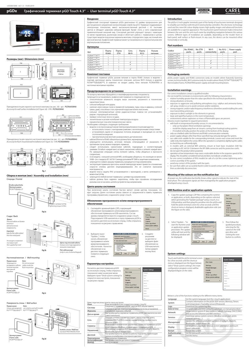
  9. Carel IR U Series User manual

Carel IR U Series User manual

IR*U* e IR*X* - Terminali e visualizzatori a led / LED terminals and displays
+050000135 - rel. 1.1 - 19.09.2007
Caratteristiche generali
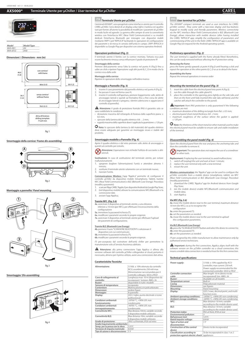
I terminali IR* U* e IR* X* (Fig. 1) collegati ad un controllo CAREL visualizzano la
temperatura trasmessa dal controllo e ne registrano eventuali anomalie di funzionamento.
Nei modelli provvisti di tasti (IR* U*) il terminale è anche in grado di impostare i valori
trasmessi dal controllo.
Cavo di collegamento
Il cavo per collegare IR*U* o IR*X* ad un controllo CAREL non è incluso; è necessario
munirsi di un cavo con le seguenti caratteristiche:
- a 3 conduttori;
- con una distanza massima di 10 mt tra il controllo e il terminale;
- sezione di 0,5…2,5 mm2.
Installazione e collegamenti (Fig. 2)
- Eseguire tutti i collegamenti elettrici necessari
C
D
B
A
estraendo i cavi dal foro del pannello
(consultare il manuale d’uso del controllo per maggiori informazioni sui collegamenti);
- Inserire il terminale nel foro del pannello
C
D
B
A
;
- Applicare le 2 staffette laterali facendole scorrere sui binari laterali del terminare
C
D
B
A
;
Per rimuovere il terminale, premere ed estrarre le 2 staffette laterali, estrarre il terminale
dal pannello ed infine togliere i collegamenti elettrici. Per l’estrazione delle staffette
premere come indicato da figura
C
D
B
A
.
Porta commissioning (Fig. 3)
I terminali IR* U* e IR* X* sono dotati di porta commissioning che permette il
collegamento tra un PC ed un controllo MPXPRO.
Per individuare tale porta nel terminale è necessario:
• Rimuovere la placchetta del terminale/visualizzatore inserendo un cacciavite a lama
piatta nell’apertura in basso a sinistra della placchetta
C
D
B
A
;
• Rimuovere la gomma della pulsantiera
C
D
B
A
;
• Collegare il cavo tLAN, in dotazione con il convertitore USB-tLAN (IROPZTLN00)
C
D
B
A
.
Consultare il manuale d’uso di MPXPRO per un corretto collegamento ed utilizzo della
porta commissioning.
Caratteristiche tecniche (Fig. 4)
Alimentazione Tensione 10…15 V ottenuta dal controllo collegato;
assorbimento 60 mA max.;
si raccomanda che l’alimentazione utilizzata per il controllo collegato
sia di tipo SELV (tipo di alimentazione con isolante galvanico di
grado rinforzato).
Contenitore Materia plastica;
dimensioni 35x76.4x39.4 mm;
profondità incasso 31mm.
Montaggio A pannello liscio, rigido ed indeformabile e mediante staffe di
fissaggio laterali, da pressare fino a fine corsa;
dima di foratura dimensioni 28.8±0.2 x 70.8±0.2 mm.
Display 3 cifre digit LED, con punto decimale sulla seconda cifra;
visualizzazione –99…999;
stati di funzionamento indicati con 10 icone grafiche sul display.
Temperatura di
funzionamento
0T50 °C
Umidità di
funzionamento
<90% U.R. non condensante
Temperatura di
immagazzinamento
-20T70 °C
Umidità di
immagazzinamento
<90% U.R. non condensante
Grado di protezione
frontale
IP65 (montaggio su pannello liscio ed indeformabile con
guarnizione)
Fig. 2
C
D
B
IR*U* (con tasti) / IR*U* (with buttons) IR*X* (senza tasti) / IR*X* (no buttons)
Montaggio a pannello IR*U* e IR*X* (visione laterale)
IR*U* and IR*X* panel mounting (side view)
Rimozione terminali IR*U* e IR*X* (visione laterale)
Removing the IR*U* and IR*X* terminals (side view)
A
1 2 3 0T50
Power
Supply
MPXPRO
Scheda base
Main Board
verso altre interfacce utente
to other user interfaces
(PSTCON0%B0)
Rx/Tx
Gnd
Power Supply
Rx/Tx
GND
GND
VL
GND
T.U.I.
Tx/Rx
25
24
26
Connessioni elettriche IR*U* e IR*X* (vista posteriore)
IR*U* and IR*X* electrical wiring (back wiew)
A B C cavo tLAN / tLAN cable
Fig. 1
Porta commissioning / Commissioning port
Fig. 3
General features
IThe IR* U* and IR* X* terminals (Fig. 1) connected to a CAREL controller display the
temperature transmitted by the controller and record any operating anomalies. In the
models with buttons (IR* U*), the terminal can also be used to set the values transmitted
by the controller.
Connection cable
The cable used to connect IR*U* or IR*X* to a CAREL controller is not included; use a
cable with the following characteristics:
- 3 wires;
- maximum distance 10 m between the controller and the terminal;
- cross-section of 0.5 to 2.5 mm2.
Installation and connections (Fig. 2)
- EMake all the electrical connections required
C
D
B
A
by removing the cables from the
opening on the panel (see the controller user manual for further information on the
connections);
- Insert the terminal in the opening on the panel
C
D
B
A
;
- Apply the 2 side brackets, sliding them on the side rail of the end
C
D
B
A
;
To remove the terminal, press and remove the 2 side brackets, remove the terminal from
the panel and finally remove the electrical connections. To remove the brackets, press as
shown in the figure
C
D
B
A
.
Commissioning port (Fig. 3)
The IR* U* and IR* X* terminals come with a commissioning port, which is used for
connection between a PC and an MPXPRO controller.
To identify this port on the terminal, proceed as follows:
• Remove the frame from the terminal/display by inserting a flat-head screwdriver in
the opening on the bottom left of the frame
C
D
B
A
;
• Remove the rubber from the keypad
C
D
B
A
;
• Connect the tLAN cable, supplied with the USB-tLAN converter (IROPZTLN00)
C
D
B
A
.
Refer to the MPXPRO user manual for the correct connection and use of the commissio-
ning port.
Technical specifications (Fig. 4)
Power supply Voltage 10 to 15 V from the controller connected;max. current
input 60 mA;
the power supply to the controller connected should be SELV
(power supply with reinforced insulation).
Case Plastic;
dimensions 35x76.4x39.4 mm;
mounting depth 31mm.
Assembly Smooth, hard and indeformable panel using side fastening
brackets, pressed in fully;
drilling template dimensions 28.8±0.2 x 70.8±0.2 mm.
Display 3 LED digits, with decimal point on the second digit;
display –99 to 999;
operating status indicated by 10 graphic icons on the display.
Operating
temperature
0T50 °C
Operating humidity <90% RH non-condensing
Storage
temperature
-20T70 °C
Storage humidity <90% RH non-condensingRH non-condensing
Front panel index of
protection
IP65 (assembly on smooth and indeformable panel with gasket)
CAREL S.p.A.
Via dell’Industria, 11 - 35020 Brugine - Padova (Italy)
Tel. (+39) 0499716611 – Fax (+39) 0499716600
http://www.carel.com – e-mail: [email protected] +050000135 - rel. 1.1 - 19.09.2007
Smaltimento
L’apparecchiatura (o il prodotto) deve essere oggetto di raccolta separata in conformità
alle vigenti normative locali in materia di smaltimento.
Disposal
The appliance (or the product) must be disposed of separately in compliance with the
local standards in force on waste disposal.
AVVERTENZE IMPORTANTI
Il prodotto CAREL è un prodotto avanzato, il cui funzionamento è specificato nella
documentazione tecnica fornita col prodotto o scaricabile, anche anteriormente all’acquisto,
dal sito internet www.carel.com.
Il cliente (costruttore, progettista o installatore dell’equipaggiamento finale) si assume
ogni responsabilità e rischio in relazione alla fase di configurazione del prodotto per il
raggiungimento dei risultati previsti in relazione all’installazione e/o equipaggiamento
finale specifico.
La mancanza di tale fase di studio, la quale è richiesta/indicata nel manuale d’uso, può
generare malfunzionamenti nei prodotti finali di cui CAREL non potrà essere ritenuta
responsabile. Il cliente finale deve usare il prodotto solo nelle modalità descritte nella
documentazione relativa al prodotto stesso. La responsabilità di CAREL in relazione al
proprio prodotto è regolata dalle condizioni generali di contratto CAREL editate nel sito
www.carel.com e/o da specifici accordi con i clienti.
IMPORTANT WARNINGS
The CAREL product is a state-of-the-art device, whose operation is specified in the
technical documentation supplied with the product or can be downloaded, even prior to
purchase, from the website www.carel.com.
The customer (manufacturer, developer or installer of the final equipment) accepts
all liability and risk relating to the configuration of the product in order to reach the
expected results in relation to the specific installation and/or equipment. The failure to
complete such phase, which is required/indicated in the user manual, may cause the
final product to malfunction; CAREL accepts no liability in such cases.
The customer must use the product only in the manner described in the documentation
relating to the product.
The liability of CAREL in relation to its products is specified in the CAREL general contract
conditions, available on the website www.carel.com and/or by specific agreements with
customers.
Grado di inquinamento ambientale 2 (normale)
PTI dei materiali di isolamento Circuiti stampati 175, plastica e materiali isolanti 175
Periodo delle sollecitazioni
elettriche delle parti isolanti
Lungo
Categoria di resistenza al fuoco Categoria D e categoria B (UL 94-V0)
Classe di protezione contro le
sovratensione
Categoria 1
Tipo di azione e disconnessione Non applicabili
Costruzione del
dispositivo di comando
Dispositivo di comando incorporato, elettronico
Classificazione
secondo la protezione contro le
scosse elettriche
Classe II per mezzo di appropriata incorporazione
Modalità di utilizzo Questo dispositivo NON deve essere tenuto in mano
mentre funziona né incorporato in apparecchiature
destinate ad essere tenute in mano.
Classe e struttura del software Classe A
Interfaccia seriale tLAN a 2 fili: Rx/Tx e GND;
parametri comunicazione di default
velocità: 9600 baud (4800, 19200 selezionabili da
parametri macchina); numero di bit: 8; parity bit:
No; stop bit: 2; protocollo standard CAREL, con
espansioni.
Indirizzo seriale IR*U*: parametro= 0;
IR*X*: parametro= 1.
Pulizia frontale dello strumento Utilizzare esclusivamente un panno morbido e non
abrasivo con detergenti neutri o acqua.
Segnalazione allarmi
‘E0’ Il controllo comunica al terminale un allarme relativo ad una anomalia di una
sonda. Ripristinata l’anomalia il controllo comunicherà al terminale di disattivare
tale visualizzazione.
‘Cn’ Il terminale non riesce a comunicare con Il controllo a causa di un problema nella
linea di comunicazione seriale. L’allarme si attiva dopo 30 secondi dall’ultima
comunicazione avvenuta. Ripristinata l’anomalia l’allarme si disattiverà automati-
camente.
‘EE’ Si è verificata un’anomalia nei parametri del terminale o del controllo master via
tLAN. Il ripristino dipenderà direttamente dall’individuazione e risoluzione del
problema. Si rinvia al manuale d’uso del controllo e/o del terminale.
Modelli
I R ________
MODELLO:
X terminale solo visualizzatore
U terminale con visualizzatore e comando a 4 tasti
COLORE:
Colori display: R= rosso
PLACCHETTA FRONTALE:
0 °C
1 °F
2 neutra
OPZIONI:
6 base senza opzioni
A con porta commissioning
7 con buzzer
B con buzzer e porta commissioning
8 con ricevitore infrarossi e buzzer
C con ricevitore infrarossi, buzzer e porta commissioning
Fig. 4
Montaggio a pannello IR*U* e IR*X* / IR*U* and IR*X* panel mounting
dima di foratura
drilling template
71x29 mm
35
76.4
38.6
31
39.4
I R ________
MODEL:
X terminal with display only
U terminal with display and 4 buttons
COLOUR:
Display colours: R= red
FRONT FRAME:
0 °C
1 °F
2 neutral
OPTIONS:
6 basic without options
A with commissioning port
7 with buzzer
B with buzzer and commissioning port
8 with infrared receiver and buzzer
C with infrared receiver, buzzer and commissioning port
Degree of environmental pollution 2 (normal)
PTI of insulating materials Printed circuits 175, plastic and insulating materials
175
Period of electrical stress across
the insulating parts
Long
Category of resistance to fire Category D and category B (UL 94-V0)
Class of protection against
voltage surges
Category 1
Type of action and disconnection Not applicable
Construction of the control device Electronic control device built-in
Classification
according to
protection against electric shock
Class II when appropriately integrated
Operating mode This device must NOT be hand held when operating
nor integrated into equipment designed to be hand
held.
Software class and structure Class A
tLAN serial interface 2 wire: Rx/Tx and GND;
default communication parameters
speed: 9600 baud (4800, 19200 can be set by
parameter);
number of bits: 8; parity: None; stop bits: 2; standard
CAREL protocol with expansions.
Serial address IR*U*: parameter= 0;
IR*X*: parameter= 1.
Cleaning the front panel of the
instrument
Only use a soft and non-abrasive cloth with neutral
detergents or water.
Alarm signals
‘E0’ The controller sends the terminal an alarm relating to a probe fault.
When the fault is resolved the controller tells the terminal to reset the display.
‘Cn’ The terminal cannot communicate with the controller due to a problem in the
serial communication line. The alarm is activated 30 seconds after the last
communication. When the fault is resolved the alarm is automatically reset.
‘EE’ A fault has occurred in the parameters on the terminal or the master controller
via tLAN. It will be reset depending on the identification and resolution of the
problem. See the controller and/or terminal user manual.
Models
This manual suits for next models

1

Other Carel Touch Terminal manuals

Carel EasySet HYPW User manual

Carel

Carel EasySet HYPW User manual

Carel pGD Series User manual

Carel

Carel pGD Series User manual

Carel pGD Touch User manual

Carel

Carel pGD Touch User manual

Carel pGDx Series Instruction Manual

Carel

Carel pGDx Series Instruction Manual

Carel MTST User manual

Carel

Carel MTST User manual

Carel pGDx User manual

Carel

Carel pGDx User manual

Carel pGDx User manual

Carel

Carel pGDx User manual

Carel PLD Series User manual

Carel

Carel PLD Series User manual

Carel pGD Touch Instruction Manual

Carel

Carel pGD Touch Instruction Manual

Carel AX5000 User manual

Carel

Carel AX5000 User manual

Carel pGD Series User manual

Carel

Carel pGD Series User manual

Carel pGD touch 7 User manual

Carel

Carel pGD touch 7 User manual

Carel PAD User manual

Carel

Carel PAD User manual

Carel pGD touch Instruction Manual

Carel

Carel pGD touch Instruction Manual

Carel pGDx Touch 4.3” User manual

Carel

Carel pGDx Touch 4.3” User manual

Carel pGD touch PGDT04000FS00 Instruction Manual

Carel

Carel pGD touch PGDT04000FS00 Instruction Manual

Carel TH Tune User manual

Carel

Carel TH Tune User manual

Carel PAD User manual

Carel

Carel PAD User manual

Carel pGD 7 Series User manual

Carel

Carel pGD 7 Series User manual

Carel pGDx User manual

Carel

Carel pGDx User manual

Carel pGDx Touch 4.3 User manual

Carel

Carel pGDx Touch 4.3 User manual

Carel pGD Series User manual

Carel

Carel pGD Series User manual

Carel AX3000 Series User manual

Carel

Carel AX3000 Series User manual

Carel pGD Series User manual

Carel

Carel pGD Series User manual

Popular Touch Terminal manuals by other brands

nvent Raychem NGC-30 installation manual

nvent

nvent Raychem NGC-30 installation manual

Festo CPV-GE-ASI-8E6A-Z Series Brief description

Festo

Festo CPV-GE-ASI-8E6A-Z Series Brief description

Motorola MK3000 Quick reference guide

Motorola

Motorola MK3000 Quick reference guide

Ingenico group Desk Series user guide

Ingenico group

Ingenico group Desk Series user guide

M2I TOPR Series Hardware manual

M2I

M2I TOPR Series Hardware manual

Avalue Technology RiPac-10P1 user manual

Avalue Technology

Avalue Technology RiPac-10P1 user manual

HP RP7 Model 7800 Illustrated Parts and Service Map

HP

HP RP7 Model 7800 Illustrated Parts and Service Map

ABB SACE Tmax XT instruction manual

ABB

ABB SACE Tmax XT instruction manual

Advantech POC-176 user manual

Advantech

Advantech POC-176 user manual

ZKTeco S922 Series user guide

ZKTeco

ZKTeco S922 Series user guide

First Data FD130 Quick reference guide

First Data

First Data FD130 Quick reference guide

Rockwell Automation Allen-Bradley 2711-TBDC installation instructions

Rockwell Automation

Rockwell Automation Allen-Bradley 2711-TBDC installation instructions

Festo CPX-FB13 Electronic manual

Festo

Festo CPX-FB13 Electronic manual

iPhotonix 7261G installation guide

iPhotonix

iPhotonix 7261G installation guide

Solux SX-DT-900 user manual

Solux

Solux SX-DT-900 user manual

Johnson Controls FlexSys MIT3-CN Installation & operation manual

Johnson Controls

Johnson Controls FlexSys MIT3-CN Installation & operation manual

GRUP ARGE HT E21 user manual

GRUP ARGE

GRUP ARGE HT E21 user manual

Siemens SIDATA 9756 installation manual

Siemens

Siemens SIDATA 9756 installation manual

manuals.online logo
manuals.online logoBrands
  • About & Mission
  • Contact us
  • Privacy Policy
  • Terms and Conditions

Copyright 2025 Manuals.Online. All Rights Reserved.