Premier Manufacturing Co. 238DB Operating manual

IMPORTANT
Read these instructions completely before installing, using or
attempting to repair this product. If you have any questions,
call Premier at (800) 255-5387 or (503) 234-9202.
Installation, Inspection, Operation
& Maintenance Guide
MANUFACTURING CO.
THE FIRST NAME IN QUALITY COUPLINGS
238DB, 245DB & 245DB-3
Bolt-On Drawbar Eyes

PREMIER MANUFACTURING COMPANY 1-800-255-5387 • www.premier-mfg.com
Page 2
Selecting The Right Equipment
Step 4: Browse Premier Product Catalog
Step 3: Considering Operating Conditions and Environments
Step 2: Determine “Tongue Weight Capacity”
Step 1: Determine “Gross Trailer(s) Weight”
Whatever your application, selecting the proper equipment for the job is very important. Proper selection along
with regular inspection and maintenance will help keep operating costs minimal while providing long life to each
component. Below are general guidelines for selecting Premier Couplings and Drawbar Eyes. If you feel that your
application is unique, please give Premier a call so that we may help you through the selection process.
Follow these four steps to ensure proper selection of Premier Couplings and Drawbar Eyes.
Step 2:
Determine “Tongue
Weight Capacity”
(Maximum occurring tongue weight)
Step 3:
Add Margin of Safety
(Dependent upon your equipment
and operating environment)
Step 4:
Browse Premier
Product Catalog
(Based on Steps 1 - 3)
Step 1:
Determine “Gross
Trailer(s) Weight”
(GVWR(s) of towed trailers)
“Gross Trailer(s) Weight” is usually determined by the Gross Vehicle Weight Rating (GVWR). This information is
attached to the trailer by the trailer manufacturer.
For “Double Trailer” configurations, only the rear trailer is considered
when selecting your Premier Coupling or Drawbar Eye. In this example, a
Coupling and Drawbar Eye with a “Gross Trailer Weight” rating of 40,000 lbs.
(18,143 kg) would be the minimum rating acceptable for normal, over-the-
road applications (see Tongue Weight section below).
For “Triple Trailers”, only the two most rearward trailers are
considered in selecting your Premier Coupling or Drawbar Eye.
In this example, a Coupling and Drawbar Eye with a “Gross
Trailer Weight” rating of 80,000 lbs. (36,287 kg) would be the
minimum acceptable for normal, over-the-road applications
(see Tongue Weight section below).
Double Trailer Configuration
Triple Trailer Configuration
Example only, each application may vary and should be considered unique.
Example only, each application may vary and should be considered unique.
40,000 LBS 40,000 LBS
40,000 LBS
Environments such as rough uneven roads or off-road use can dramatically increase shock loads to both drawbar
eyes and couplings. In general, increasing the “Gross Trailer Weight” (Step 1:) and “Tongue Weight Capacity”
(Step 2:) by a minimum of 25% will be sufficient for many applications. Even if an application is used off-road
occasionally, the minimum increase necessary for Gross Trailer and Tongue Weight is 25%. Certain types of
equipment and/or operating practices can also dramatically increase loads through equipment binding and/or
improper loading practices. Of special concern is high tongue weight. However, each application is unique and
every environment different, therefore your application may require more than 25%.
Once both “Gross Trailers(s) Weight” (Step 1:) and “Tongue Weight Capacity” (Step 2:) have been determined,
evaluate your operating conditions and apply an appropriate margin of safety.
Browse the Premier Product Catalog and refer to the “Specifications” section of each product. Be sure to review
the “Understanding Premier Load Specifications” section and “Coupling to Drawbar Eye Cross-Reference” sheet
on the next couple pages.
“Tongue Weight Capacity” is the maximum expected weight at
the drawbar eye. If a hinged drawbar is used, the maximum weight
will be approximately 1/2 the overall drawbar weight. If a non-hinged
drawbar is used and the actual tongue weight is not known, you can
approximate the weight by multiplying the GVWR of the towed trailer
by 15%. However, each application is unique and the best practice is
to weigh the tongue when the trailer is loaded to its GVWR.

1-800-255-5387 • www.premier-mfg.com
PREMIER MANUFACTURING COMPANY Page 3
premier manufacturing company 1-800-255-5387 • www.premier-mfg.com 5
Understanding Premier Load Specifications
Selecting The Right Equipment
SAMPLE ONLY
5
Weight of Trailer(s) being towed
(see Steps 1-4 on page 4).
Maximum occurring tongue
weight. Static as well as dy-
namic loads.
Maximum load on latch
or upper coupling surface
containing drawbar eye.
Latches and upper coupling
surfaces are not designed
for sustained load at this
stated capacity.
The largest x-section in
eyelet portion of eye. Used to
determine compatibility
with coupling.
Minimum inside diameter
of eyelet portion of eye.
Used to determine
compatibility with coupling.
Weight of unit or pair of
units without accessories.
Each Premier product undergoes extensive design and testing prior to being introduced. We use the latest in
Computer Aided Design and Analysis Software as well as physical destructive tests. Premier’s published load
specifications are the maximum load a given product or part will withstand without failure. Premier’s testing
procedures closely follow the Society of Automotive Engineers (SAE) guidelines of Recommended Practice for
testing Couplings and Drawbar Eyes (SAE J847 & J849).
Maximum Gross Trailer Weight:
Maximum Tongue Weight:
Ultimate Latch/Upward Vertical Capacity:
Maximum Eye X-Section:
Minimum Eye Opening:
Unit Weight:
30,000 lbs. (13,607 kg)
4,500 lbs. (2,041 kg)
5,000 lbs. (2,267 kg)
1 13/16 in. (46 mm)
2 in. (51 mm)
12.6 lbs. (5.7 kg)
Customer Service: We are always here to support you. Do you need additional information or assistance? Your
phone calls are greeted by our courteous receptionist, during business hours. We have exceptional, personable
Customer Service Reps for you to rely on. If you have product questions or want to place an order, you can speak
directly with one of our experienced and knowledgeable Customer Service Representatives.
Sales Representatives: Would you like on site training or assistance? Contact one of our veteran Premier Sales
Reps for more information about product training for your staff. Or be sure to visit with them at a Trade Show (see
website for schedule).
www.premier-mfg.com: Our website is an informative resource at your fingertips. In addition to our Installation
and Service Guides, you will find our Sales Representatives, distributor locations, online catalog pages, product
specifications, how to select product, trade show schedule, and links to trucking resources.
Additional Product Resources at Your Fingertips
Importance of Inspection and Maintenance
Safety is our #1 Priority: Through high quality designs and unsurpassed quality control procedures, Premier
assures our customers that our focus on safety continues to be our #1 priority.
Scheduled Inspection & Maintenance: Regularly scheduled inspection and maintenance are essential for
maintaining safe and efficient operations whether you are using Couplings, Drawbar Eyes, Jacks, Hinge Assemblies,
or any other Premier product. Inspection and maintenance are necessary for proper function and will also keep
repair costs to a minimum.
Technical Literature: Premier provides important literature to assist you with our products. We package and attach
Installation, Inspection, Operation & Maintenance Guides, or Service Guides, to each of our major products. This
literature is also available to view and/or print from our website at www.premier-mfg.com. These supply you with
important information and help guide you through installation, inspection, operation, routine maintenance and part
replacement.
Wear Gages: In accordance with the Federal Motor Carrier Safety Regulations, we created Wear Gages to assist
you in determining the wear limits of Premier couplings and drawbar eyes. See details on catalog pages 7 & 75.

PREMIER MANUFACTURING COMPANY 1-800-255-5387 • www.premier-mfg.com
Page 4
premier manufacturing company 1-800-255-5387 • www.premier-mfg.com
6
Coupling - to - Drawbar Eye, Cross Reference Chart
Selecting The Right Equipment
2*
3
4
5
6/6A
8
11
20
21
22
23
107
108
110
123
125
126
127
200
200L
203
205
207
238DB
245DB
245DB-3
300
304
305
306
307
309
405
407SE
410
16 •••••••••••••••••••••••••••••••••••
24 •
40 •
100 †••••••••••••••••••••••••••• •••••
100-3 †•••••••••••••••••••••••••••••••••
100-4 †•••••••••••••••••••••••••••••••••
100-4H †•••••••••••••••••••••••••••••••••
130 •••••••••••••••••••••••••••• ••••
135NT ••••••••••••••••••••• •••••• •
140 • • •
150 •••••••••••••••••••••••••••••••••
160 •••••••••••••••••••••••••••••••••••
235NT •••••••••••••••••••• •••••• •
240 •••••••••••••••••••••••••••• •••••
240K •••••••••••••••••••••••••••••••••
270 •••••••••••••••••••••••••••••••••
290 •••••••••••••••••••••••••••••••••
360 •••••••••••••••••••••••••••••••••
370 •••••••••••••••••••••••••••••••••
370B •••••••••••••••••••••••••••••••••
470 •••••••••••••••••••••••••••••••••
470H •••••••••••••••••••••••••••••••••
480 •••••••••••••••••••••••••••••••••
570 •••••••••••••••••••••••••••••••••
580 •••••••••••••••••••••••••••••••••••
580J •••••••••••••••••••••••••••••••••
590 •••••••••••••••••••••••••••••••••••
690/690T •••••••••••••••••••••••••••••••••
770 •••••••••••••••••••••••••••••••••
780 •••••••••••••••••••••••••••••••••
790 • •••••••
880 • •••••••
890/890C ••••••••• •••• •••• ••••• •
2200 •••••••••••••••••••••••••••••••••
2300 •••••••••••••••••••••••••••••••••
2300B •••••••••••••••••••••••••••••••••
2400 •••••••••••••••••••••••••••••••••
2400H •••••••••••••••••••••••••••••••••
2880 • •••••••
Couplings
Drawbar Eyes
† Saf-Tite Product
* Industrial Application
CAUTION: Verify that both the coupling’s and drawbar eye’s rated capacities
meet your application(s) requirements.

1-800-255-5387 • www.premier-mfg.com
PREMIER MANUFACTURING COMPANY Page 5
SAFETY WARNING
This product is designed for towing under
normal conditions within the stated gross
trailer weight. Do not overload or abuse this
product. Overloading or abuse may lead to
property damage, severe injury, or death.
238DB, 245DB & 245DB-3 Bolt-On Drawbar Eyes
238DB STANDARD INSTALLATION DRAWING
SPECIFICATIONS AND LOAD CAPACITIES
245DB STANDARD INSTALLATION DRAWING
Inside Diameter:
Unit Weight:
3 in. (76 mm)
27.8 lbs. (12.6 kg)
Max. Gross Trailer Weight:
Maximum Tongue Weight:
90,000 lbs. (40,823 kg)
8,000 lbs. (3,628 kg)
Inside Diameter:
Unit Weight:
2 3/8 in. (60 mm)
41.6 lbs. (18.9 kg)
245DB-3 STANDARD INSTALLATION DRAWING
Inside Diameter:
Unit Weight:
3 in. (76 mm)
42 lbs. (19.1 kg)
1-800-255-5387 • www.premier-mfg.com
PREMIER MANUFACTURING COMPANY Page 6
238DB, 245DB & 245DB-3 Bolt-On Drawbar Eyes
INSTALLATION
Installation Procedure:
1. The 238DB, 245DB and 245DB-3 Drawbar Eyes
must be installed to comply with the Federal
Motor Carrier Safety Regulations. Specifically,
Section 393.70, Paragraph C: “Towing of Full
Trailers.” Prior to install or operation, consult
with local, State and Federal agencies, as there
may be additional applicable laws governing
installation and use of this product.
2. Drill six 41/64” diameter mounting holes in the
mounting structure as outlined in the Standard
Installation Drawing. NOTE: Seven mounting
holes are required for model 238DB.
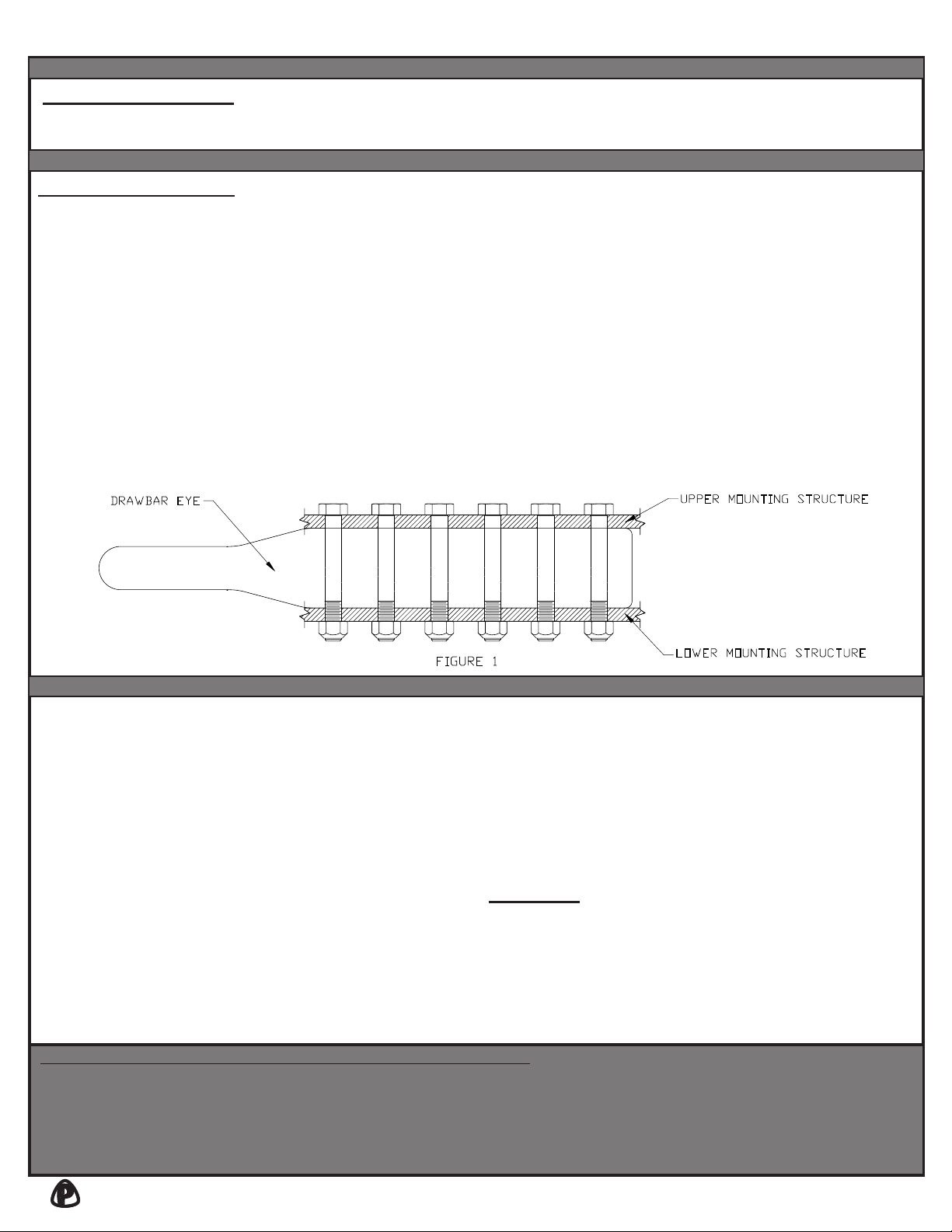
3. Secure the 238DB, 245DB or 245DB-3 Drawbar
Eye using 5/8” grade-8 bolts and grade-C
locknuts. Torque nuts to SAE specifications.
THE MOUNTING STRUCTURE MUST
ATTACH TO BOTH THE UPPER AND LOWER
SURFACES OF THE DRAWBAR EYE, AS
SHOWN IN FIGURE 1. ALL BOLT HOLES
MUST BE USED.
4. An “IMPORTANT WARNINGS!” sticker was
enclosed. This must be attached to the front
end, adjacent to the drawbar eye, visible for the
end user to read.
1. Visually inspect the drawbar eye for cracks,
impact damage and/or deformation before each
and every use. Do NOT use if any of these
conditions exist.
2. Check all fasteners to make certain that they
are secure before each and every use.
3. If the original cross-section of the eye loop has
been reduced by 20% or greater, the drawbar
eye is NOT to be used and is considered out-of-
service.
4. This product is designed to be operated within
its free rotation limits. It is the responsibility of
the vehicle designer/end user to assure that
these limits are not exceeded (do not bind-up/
jackknife).
5. WARNING: Prior to towing, make certain that
adequately rated safety chains have been
properly connected.
6. Never weld on any Premier drawbar eye in
order to repair damaged or worn areas. Field
and/or shop weld repairs are inadequate and
may further weaken the drawbar eye.
WARNING: OTHER INSPECTIONS AND
PROCEDURES ARE ALSO REQUIRED
PRIOR TO OPERATION OF COMBINATION
VEHICLES. CONSULT AND FOLLOW ALL
FEDERAL MOTOR CARRIER SAFETY
REGULATIONS AS WELL AS LOCAL OR
STATE/PROVINCE GUIDELINES.
ACCESSORIES
Optional Accessories:
- 14005 (1 5/8”) Wear Gage: Used to determine if the eye has worn beyond its intended service life.
INSPECTION / OPERATION / MAINTENANCE
- Never attempt weld repair of damaged or worn drawbar eyes
- Air adjusted drawbar eyes must be used with an air service chamber or
#500 slack adjuster
- Only Grade-8 fasteners properly torqued should be used when attaching
bolt-on drawbar eyes
- Clean and inspect drawbar eyes and eye assemblies for damage or
excessive wear before each and every use
- Structure to which eye is attached must be of sufficient strength to
withstand load rating of eye
- Do not bind-up (Jackknife) any application as stresses can cause damage to products
or components, resulting in failure and detachment of the trailer while in use
- Do not apply lubricants to the coupling hook or drawbar eye loop, as they can cover
up possible damage and accelerate wear
IMPORTANT GUIDELINES that apply to all Premier Bolt-On Drawbar Eyes
LOWER MOUNTING STRUCTURE
UPPER MOUNTING STRUCTURE
DRAWBAR EYE
FIGURE 1

(1) VERIFY THAT BOTH COUPLING’S AND
DRAWBAR EYE’S RATED CAPACITIES MEET
YOUR APPLICATION(S) REQUIREMENTS.
(2) DO NOT OVERLOAD COUPLING OR DRAWBAR
EYE.
(3) INSPECT COUPLING, LATCH AND DRAWBAR
EYE FOR CRACKS, BENDING DAMAGE OR
EXCESSIVE WEAR. DO NOT USE IF ANY OF
THESE CONDITIONS EXIST!
(4) CHECK FOR GAP BETWEEN CLOSED LATCH
AND TOP OF HORN OR COUPLING BALL.
DO NOT USE IF GAP IS 3/8 IN. OR MORE.
(5) MAKE SURE COUPLING IS LATCHED AND THAT
LATCH WILL NOT OPEN.
(6) PRIOR TO USE, ALWAYS CONNECT SAFETY
CHAINS OF ADEQUATE STRENGTH FOR
LOAD(S) BEING TOWED.
(7) DO NOT BIND-UP (JACKKNIFE) ANY
APPLICATION AS STRESSES CAN CAUSE
DAMAGE TO THE COUPLING, DRAWBAR EYE,
OTHER COMPONENTS OR ANY COMBINATION
OF THEM. JACKKNIFING MAY RESULT IN
FAILURE OF PRODUCTS OR COMPONENTS,
RESULTING IN DETACHMENT OF THE TRAILER
WHILE IN USE.
(8) DO NOT APPLY LUBRICANTS TO THE COUPLING
HOOK OR DRAWBAR EYE LOOP, AS THEY
CAN COVER UP POSSIBLE DAMAGE AND
ACCELERATE WEAR.
(9) ALWAYS ABIDE BY ALL APPLICABLE STATE AND
FEDERAL REGULATIONS GOVERNING SAFE
AND PROPER TRANSPORTATION.
(10) NEVER STRIKE ANY OF THESE COMPONENTS
WITH A HAMMER OR ANY OTHER DEVICE.
(11) ALWAYS VERIFY PROPER OPERATION
OF LATCHING SYSTEM AND COUPLING
COMPONENTS PRIOR TO DRIVE OFF.
(12) NEVER USE A COUPLING THAT YOU DO NOT
FULLY UNDERSTAND HOW TO PROPERLY
OPERATE AND VERIFY SECURE LATCHING OF.
(13) NEVER REPLACE ANY PART IN ANY OF
PREMIER’S ASSEMBLIES WITH NON-PREMIER
COMPONENTS. DOING SO WILL VOID ALL
WARRANTY AND POTENTIALLY COMPROMISE
THE UNIT’S INTEGRITY, WHICH COULD RESULT
IN PROPERTY DAMAGE, SERIOUS INJURY, OR
DEATH.
ATTENTION !
End Users must read and follow this information.
DISTRIBUTORS & OEM’S: Please ensure that your customers
are made aware of the following information on this page.
1-800-255-5387 • www.premier-mfg.com
PREMIER MANUFACTURING COMPANY Page 7

WARRANTY: We warrant all Premier products to be free from defects in material or workmanship for one year. We
will repair or replace, at our option, any Premier product which our examination reveals to be defective, provided
that the product is returned to our factory, at Tualatin, Oregon transportation prepaid, within one year of purchase
by the first retail purchaser. Our warranty does not extend to products which have been subject to misuse, neglect,
improper installation, maintenance or application, nor does our warranty extend to products which have been
repaired or altered outside of Premier’s facility unless the repair or alteration has been expressly authorized in
writing by Premier. This warranty is in lieu of all other warranties, express or implied, and excludes
warranties of merchantability, fitness for a particular purpose and otherwise, and in no event will Premier
be liable for incidental, special, contingent or consequential damages.
DISCLAIMER: Although great care has been taken to ensure accurate information throughout this document,
Premier Manufacturing Company must reserve the right to alter any information contained within. These changes
include but are not limited to: Dimensional changes, load capacity and availability of any part or assembly.
© 2009 Premier Manufacturing Company
All rights reserved. Any reproduction of the photographic images or any other portion of this document, including but not limited to the photocopying, or retention and/or storage
in a retrieval system of any kind, is strictly prohibited without prior express written permission from Premier Manufacturing Company.
WARNING!
This envelope contains important
instructions AND MUST REMAIN
ATTACHED TO THIS DRAWBAR
EYE. It may be removed only by the
End User or by an Original Equipment
Manufacturer who preserves this
envelope and instructions and
provides it to the end user.
PREMIER MANUFACTURING COMPANY
THE FIRST NAME IN QUALITY COUPLINGS
800-255-5387 (503) 234-9202
www.premier-mfg.com
1-800-255-5387 • www.premier-mfg.com
PREMIER MANUFACTURING COMPANY Page 8
Revised: 11/13
238DB, 245DB & 245DB-3
Bolt-On Drawbar Eyes
Installation, etc.
This manual suits for next models
5
Table of contents
Other Premier Manufacturing Co. Automobile Accessories manuals


Popular Automobile Accessories manuals by other brands


ULTIMATE SPEED
ULTIMATE SPEED 279746 Assembly and Safety Advice

SSV Works
SSV Works DF-F65 manual

ULTIMATE SPEED
ULTIMATE SPEED CARBON Assembly and Safety Advice

Witter
Witter F174 Fitting instructions

WeatherTech
WeatherTech No-Drill installation instructions

TAUBENREUTHER
TAUBENREUTHER 1-336050 Installation instruction