1-800-255-5387 • www.premier-mfg.com
premier manufacturing company Page 2
pull sideways, removing it from the body. When the
896 Handle is removed, the 895 Latch and 895A
Spring are also free to be removed. Please note that
Thread Locker is used to secure the 895C Set Screw.
Therefore it may be necessary to slightly heat-up the
part with a torch, in order to remove the set screw.
CAUTION: Do Not apply heat to the 895A Spring or
permanent damage will occur.
12) If the 891P Pin & Cable are damaged, you can
now remove them. Using a chisel or flat-bladed
screwdriver placed at the base of the 16DS Drive
Screw, tap with a hammer to wedge the 16DS up and
out of the hole it resides in, and remove the 891P Pin
& Cable.
13) Disassembly is now complete. Clean and inspect
parts and body for wear and/or damage. If wear
exists or damage is noted, replace affected
part. NEVER ATTEMPT WELD REPAIR OF ANY
DAMAGED OR WORN COMPONENT.
DISASSEMBLY IS COMPLETE
IMPORTANT NOTES TO CLEAN,
INSPECT & LUBRICATE:
► Use only genuine PREMIER replacement parts on
any repairs. Use of other parts, which can have
different specifications or tolerances, may fail to alert
you to non-obvious damage to the hitch which can
lead to hitch failure.
► All body holes, part holes and pins need to be
thoroughly cleaned and lubricated with a heavy
grease before the parts are reassembled. If a bushing
resides in a part, lubricate the hole prior to installing
the bushing. (DO NOT LUBRICATE PINTLE HOOK
WEAR SURFACE).
► Clean, inspect and lubricate latch components
every 90 days or sooner if required by the operating
environment.
► Clean and inspect the coupling for damage and
excessive wear prior to each and every use.
► Do not over-tighten fasteners as this may cause
damage.
ASSEMBLY
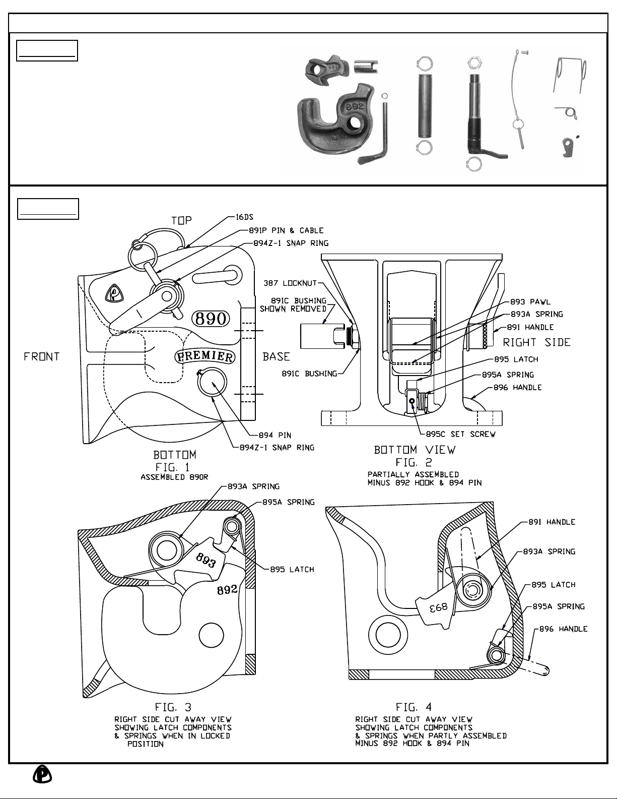
1) With the coupling body positioned on its topside as
shown in Image #2, Fig. 2. Slide 896 Handle into
the body from the right side until approx. 1/2” of the
handle is protruding past the inside surface of the
body.
2) Place the 895A Spring inside body onto the
protruding portion of the 896 Handle, to temporarily
hold the 895A Spring in position. Straight spring leg
will be pointing towards you. (See Image #2, Fig. 2
for spring position.)
3) Place 895 Latch into position, making certain that
the spring catch on the spring is located on the long
flat side of the part. While holding the 895 Latch in
position, slide 896 handle thru the 895 Latch and
continue thru the other body sidewall until snap ring
groove is exposed. (See Image #2, Figs. 2 & 4 for
spring and latch position.)
4) Locate counter-drilled hole in 896 Handle and align
it with the tapped hole in 895 Latch. Install 895C Set
Screw into 895 Latch, making certain it maintains
alignment with 896 Handle counter-drilled hole, and
then tighten in position. 895C Set Screw should
be flush with the surface of the 895 Latch. If it is
protruding, it is not aligned with the counter-drilled
hole in the 896 Handle. (See Image #2, Fig. 4 for
approx. handle position when completed.) Use a
permanent thread locker to secure the 895C Set
Screw.
5) Rotate the 896 Handle counterclockwise checking
for spring resistance. If the 895A Spring is installed
correctly, a smooth increasing spring resistance
should be felt when handle is rotated. If no
resistance or binding is felt, the spring and/or part is
not installed correctly and must be corrected prior to
proceeding further.
6) Install 275-50 Snap Ring into groove provided on the
end of the 896 Handle. Install the 894Z-1 Snap Ring
into groove provided on 891 Handle.
7) From the left side of the body, insert the 891C
Bushing into the hole (where the 891 Handle will
reside), with the cut out lugs going inward first. Make
sure the 891C Bushing is flush with the interior body
wall.
8) Place 893A Spring into body (opened spring legs
pointing away from you), and align spring with the
hole that the 891C Bushing is resting in. When
aligned, push 891C Bushing into spring loop just
enough to hold spring in position. (See Image #2,
Figs. 2 & 4 for spring position and orientation.)
9) Grasp 893 Pawl and lower into position, making
certain the closed loop of the spring is closest to you
and catch the backside of the 893 Pawl on the spring
as shown in Image #2, Fig. 4. Align the 893 Pawl