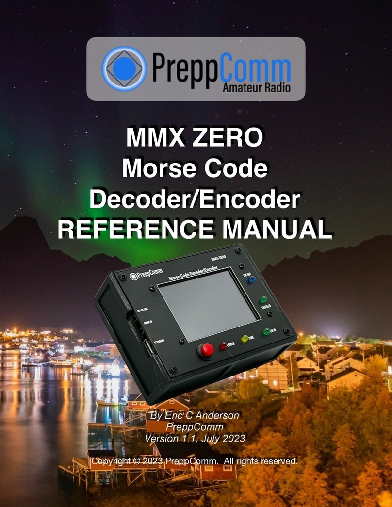
PreppComm MMX-804020 User manual

Morse Made Easy™
MMX MultiBand Transceiver
MMX ZERO Decoder/Encoder
QUICK START GUIDE
By Eric C Anderson, PreppComm
Version 1.2, July 2023
Copyright © 2023 PreppComm. All rights reserved.!

Copyright © 2023 PreppComm. All rights reserved.
I. Introduction
There are two ways to use the MMX transceiver. For MMX ZERO, only the second one
is available:!
1, Sand-alone QRP Transceiver
2. Companion or assistant for decoding/encoding to your existing transceiver
In this Setup Guide, we will first cover setting up the MMX itself for operation, followed
by Electrical Setup and then Operation for each of the two modes in separate sections.
II. MMX Computer Setup
The MMX start up in External Mode, or Companion Mode, and is discussed in detail in
Section II. This is displayed in the Frequency Button. In Figure 1 below, the Frequency
Button shows a 40M frequency, so this is clearly not a MMX ZERO screen, which
always shows External in the Frequency Button space.
1. Connect the MMX to a power source, and press the red Power button. The
Splash Screen will display for approximately 3 seconds, followed by the Main Screen
then is displayed, as shown in Figure 1 below.
FIGURE 1: MAIN SCREEN
Spend a few moments to review the screen tags above. Take particular attention to the
CCS Button (CCS = Captured Call Sign) and the Frequency Button, which at first
Page 2

Copyright © 2023 PreppComm. All rights reserved.
power on reads External. For the MMX ZERO, the Frequency Button always shows
External, as there is no transceiver or VFO installed.
2. Press the Menu Button, and the Main Menu screen will display, as shown in
Figure 2 below.
FIGURE 2: MAIN MENU
Note that Graphics and Firmware version numbers are now displayed in the lower
bottom corners of the Main Menu (not shown here).
3. Press the LOCAL STATION SETUP button at the top of the menu. The Call Letters
entry screen will display, as shown in Figure 3 below:
FIGURE 3: CALL LETTERS ENTRY SCREEN
Page 3

Copyright © 2023 PreppComm. All rights reserved.
4. Enter your call letters assigned to you by the FCC. Use backspace or delete to
edit if you make a mistake. Note: you do not have to hold down the caps key - all caps
is automatic. Press the NEXT button to continue.
5. Using the NEXT buttons, proceed through a series of screens and enter the
required information
a) Name, or in ham radio lingo, your Handle, such as JOHN
b) Location, or QTH in ham lingo, such as CHICAGO, IL
c) Rig Type (PREPPCOMM MMX)
c) Antenna Type. The antenna you are using, or DUMMY LOAD.
d) License Level. Select your FCC license level
The License Level Entry screen is shown in Figure 4 below
FIGURE 4: LICENSE LEVEL ENTRY SCREEN
6. Press the FINISH button on the License Level Screen
You will be returned to the Main Screen. You have now completed initial setup of your
MMX transceiver.
7. Press the Menu button again, followed by the Typing Speed button. You will see
the Typing Test screen shown in Figure 5 on the next page. Why are we taking a typing
speed test now? Because you want to establish the upper limit of how fast the
transmitter should be allowed to transmit Morse code, right at the start. Normally, the
encoder typing speed is set by the decoder, based on the speed of the other station.
However, if you can’t send as fast as the other station, you need to let the computer
know, so it will limit the WPM (Words Per Minute) based on your ability to type. This is
important to enable well-formed Morse communications. If the transmitter is running too
Page 4

Copyright © 2023 PreppComm. All rights reserved.
fast, it will end up pressing you to type faster, making more mistakes, not to mention not
having fun. So take the time now to do this important setup step, unique to PreppComm
Morse transceivers. Follow the directions on the screen
Figure 5: Typing Speed Test
The result? Your transmit speed will match the other station unless it is going too fast, at
which point your speed will be set to the maximum allowed.
Once you complete the test, you will see the screen shown in Figure 6 below:
FIGURE 6: TRANSMITTER MAXIMUM WPM
The value you see on this screen is the maximum WPM the transmitter will transmit. To
be clear, for MMX ZERO, this means the maximum WPM of the Morse Encoder, so the
Page 5

Copyright © 2023 PreppComm. All rights reserved.
maximum transmit speed of the external transceiver. This is a computed value, based
on a number of factors. Go with it for now - you can always come back and edit it. Press
SAVE to complete the setup.
8. Initial setup of the MMX is now complete.
III. Learning Auto-CALL and ANS
In this section we are going to familiarize you with using the four different call and
answer functions built into the MMX. These work the same for both external and internal
transmitters.
If not in External Mode already, press the Frequency Button until it shows
External. Then, follow the following steps.
1. Press CALL. On the status line, you will see the question SET CALL WPM = ?
Asking you to specify how fast to transmit, as there is no history to base that on
at this first transmission, and the CALL button will turn RED.!
2. Press SPACE BAR to set the default 20 WPM. You can change the default later
if you wish. If you are not hearing tone output, adjust your volume control and
check your wiring. If all else fails, exit CALL by pressing ESC and press K, and
try pressing CALL again. K toggles the tone output on/off. ESC is the instant,
emergency exit from transmit mode. ESC has a number of other functions not
covered here.!
3. Watch as the MMX transmits the general call or CQ, using your call sign.!
4. Press CALL to end the call. The current repeat continues until complete, and
ends with a Kappended. The CALL button will turn AMBER during the ending
of the call. K means "Come Back (anyone).” Note that the general call will
repeat until you end it. Typically you will run it for 30 - 90 seconds when on the
air.!
5. Press NO CCS button and enter the call letters of a station you would like to
call. Press SPACE or FINISH to complete and return to the Main Screen.!
6. Note the CCS Button now has the new call sign you just entered loaded.
Normally, the decoder will fill the CCS button from a received station ID.!
7. Press CALL again to start a directed call. Note it will automatically use 20 WPM
from recent history, your call sign, and the call sign you entered into CCS.!
8. Watch as the MMX calls the specified station. Press CALL again to end the
directed call. Note that KN is appended at the end, which means "come back,
Page 6

Copyright © 2023 PreppComm. All rights reserved.
only the station I am calling.”!
9. Press the ANS Button twice, quickly. The first press will result in a RED
button, the second press will result in an AMBER button. Ignore the Type-Ahead
Buffer Pop-Up for now.!
10. Watch as the MMX transmits the answer-validate sequence. This is a short
station ID used when you are responding to another station’s CQ (general call) to
attempt to establish a 2-way communication. If they answer you, then a 2-way
has been established, and communication can begin. Answer Validate is not
required if you make a call and someone answers you. In this case, you are
using a CCS you entered. Normally, the CCS would have been set by the station
calling CQ.!
11. Press ANS once. The button turns RED, and a Type-Ahead Buffer pops up.
12. Type a tilde (~) character, then press ANS again. The button turns AMBER.!
13. Watch as the MMX sends the initial station ID, followed by the INFO text
message, which is generated when you type in a tilde character. The Type-
Ahead Buffer goes away as soon as the tilde is read out. The final station ID
back to the other station completes the transmission, with a KN.!
!
The key in this step is to understand the use of ANS pressed once, and using the
tilde character to send the INFO message automatically from your information
previously entered. You can create your own INFO message with microprograms
later.!
14. Think up a short message, such as "HI, BOB. HOW ARE YOU TODAY?"!
15. Press ANS and IMMEDIATELY type your message. You should be able to
type at least part of the message during the initial auto station ID, and then your
message will begin to transmit.
16. Press ANS again to indicate to the computer that your typing is complete. Your
message will first appear in the Type-Ahead Buffer, until the initial auto station ID
has completed, and then your message will be read out one character at a time,
and reappear as transmitted text in the main text area. Finally, since you pressed
ANS the second time, it completes the transmission with another station ID.!
!
The use of ANS to go back and forth with another station is very easy and
simple, but it does mean an auto ID at beginning and end of each transmission.
You can change this easily with simple microprograms. You can also “press” the
CALL and ANS buttons using function keys (or press YOUR call and answer
function), also using microprograms.!
!
Page 7

Copyright © 2023 PreppComm. All rights reserved.
These built-in microprograms (CALL, ANSWER, and INFO) can be customized
and controlled from function keys using RPL (Rig Programming Language) in our
microprogramming system. There are 12 user-defined microprograms. Watch
our YouTube video on microprogramming to get the "starter set" to play with. The
starter set is also described in Section 18-10 of the MMX Reference Manual.!
17. You now have a basic idea of how to use the four main transmit functions:
1. General Call
2. Directed Call
3. Answer-Validate
4. Answer
This completes the basic training of the automated CALL-ANS functions.
Page 8

Copyright © 2023 PreppComm. All rights reserved.
IV. Choose your mode of operation
There are two more sections to the Guide:
1. QRP Transceiver: Getting started using your MMX as a QRP (low power)
Transceiver. This is referred to as the "Transceiver Mode." In this use, you need
the MMX, keyboard, headphones, battery, and an antenna (or dummy load if you
are learning how to use it). Go to Section III below.!
2. External Transceiver Decoder/Encoder: This is for when you want to
connect your MMX to your base station transceiver to use as a CW decoder/
encoder. This is referred to as the "External Mode or Companion Mode." This
mode enables use of the internal computers for decoding and encoding, and uses
the receiver and transmitter inside your base or portable station transceiver. This
allows the decoder and encoder to operate on any band your base station operate
on, and at a higher power level, set by your base station. This is also the MMX
ZERO mode Go to Section VII.
Page 9

Copyright © 2023 PreppComm. All rights reserved.
V. QRP Mode Electrical Setup
1. Set up the MMX as shown in Figure 7 below. Take care plugging in connectors.
FIGURE 7: STATION SETUP AS STAND-ALONE STATION
2. Turn on the transceiver using the RED power switch.
WARNING: NEVER OPERATE THE TRANSMITTER WITHOUT A LOAD ON THE
ANTENNA CONNECTOR. DOING SO VOIDS YOUR WARRANTY FOR ANY
DAMAGE CAUSED BY AN UNLOADED TRANSMITTER.
If you plan to use a key to transmit, this will be covered at the end of this section.
Page 10

Copyright © 2023 PreppComm. All rights reserved.
The MMX start up in External Mode, or Companion Mode, and is discussed in detail in
Section IV. Pressing External Mode on the LCD Display (Frequency Button in Figure 1)
switches to your lowest band transceiver function. Pressing repeatedly will cycle
through the available bands and External Mode.
The Receive Mode Keyboard for the MMX is shown below. There is a large version for
printing out in Appendix VI of the MMX Reference Manual. It is a good idea to print out a
copy so you can refer to it as you learn the keyboard receive mode commands.
FIGURE 8: MMX RECEIVE MODE KEYBOARD COMMANDS
Here are a few things to take note of at this time:
1. The < and > keys (unshifted, so the comma/period keys) control the headphone or
powered speaker volume.
2. Delete and Backspace work the same - they delete the previously entered character,
if it is still available to be deleted.
3. The Space Bar restarts the decoder, and causes the Speed and Hand Algorithms to
be run after collecting data. CRITICAL FUNCTION at the beginning of any new CW
code stream!
4. The B backlight toggle: use this to turn on/off the backlight. The 3-minute auto-turn
off is still there, and when you turn the backlight back on, a new 3-minutes timer
begins (for no activity on the screen). Any activity will also restart this timer.
Next we will look at using the receiver.
Page 11

Copyright © 2023 PreppComm. All rights reserved.
VI. QRP Mode: Using the Receiver
1. Background
Obviously, the first thing you need to do to tune in a station is... remove the dummy load
(if you used one) and connect to a real antenna. A good antenna is a critical aspect of
any radio station. Since you are running QRP (Low Power), a good antenna is truly a
MUST.
One one level, tuning in a station is fairly simple: you scan up or down the band looking
for a signal, and stop and adjust around the signal so that it is decoding correctly. On
the other hand, it can be quite daunting.
Why can it be daunting? There are several reasons that you need to be aware of. First
and foremost is the "band condition." The band can be "open" or "closed." It depends
primarily on the sunspot cycle, the current sunspot activity, and time of day. If you hear
nothing on the band, the band is probably closed, or, as they say, DEAD. Try later.
However, a dead band does not mean you can’t connect with someone nearby (local).
If you have a scheduled time and frequency to meet, even if the band is dead, i.e., long
distance communications is out, local can still work quite well, depending on your
antenna. Typically, the 40 meter band opens in early to mid afternoon, and is open at
various distances - ever growing farther and farther away - until very early morning. By
that I mean oh-dark-thirty. It’s all about the ionosphere and its height above the earth. It
rises at night, and thus your "skip" distance increases.
2. Receiver Incremental Tuning
After transmitting, that the Frequency Button changes to show RIT +0. RIT stands for
Receiver Incremental Tuning. This decouples the receiver frequency from the
transmitter frequency. The transmitter frequency remains constant, but you can make
minor adjustments to the receiver frequency, as needed. Specifically, when another
station comes back to you the first time, their frequency may be slightly off, and you
may need to adjust the receiver frequency for optimal decoder operation. More on that
below.
3. Receive Mode Keyboard Commands
Page 12
NOTE: For this section, you will need a real antenna, and the Frequency button
should show a frequency value, not External. Press the button to switch to an
available band, which turns on the transceiver inside the MMX.

Copyright © 2023 PreppComm. All rights reserved.
Figure 8 above is a diagram showing the receiver keyboard commands. You can tell
that you are in Receive Mode because both the CALL or ANS Button are BLUE. Press
MENU / HELP / RECEIVE for a summary of these commands. The commands are on
two separate screens, which you can access via the NEXT and PREVIOUS buttons.
The EXIT button or the keyboard ESC will return you to the Main Screen.
Note that on the Help Screen, there is also help for TRANSMIT and MICROPROGRAM
commands, as well.
There is a large version of this layout in Appendix VI of the MMX Reference Manual
you can use print out and as a guide. For now, just note the following keys:
a. the 4-way Receiver Frequency Control keys (bottom right)
b. the Gain Control keys, (to the left of the frequency controls)
c. the Restart Decoder (space bar) key.
Note that the initial frequency display shows the QRP Calling Frequency for the
selected band, and the initial frequency step size of 1 Hz. 7.03 MHz is the small signal
calling frequency for 40 meters, for example.
4. Volume Controls
There are two separate volume or gain controls on the MMX. One controls the audio
volume going to the headphone jack. The other controls the signal gain to the decoder.
The default values are 10 and 30, and are shown at the bottom left and right of the Main
Screen (see Figure 3).
Try adjusting both now, using the keys with or without the shift key down, watching the
values change on-screen. For weak signals, increase the decoder gain to 40. For
strong signals, you may need to reduce below 30. Audio setting is for your preference.
5. Tuning Practice
1. Press the right arrow key. Note the frequency has increased 1 Hz. You have
increased the receiver frequency by 1 Hz.!
2. Press and hold the right arrow key, and after 1 second, auto-repeat on the
keyboard kicks in. Now you see the frequency step up in 1 Hz intervals.!
3. Press the up arrow key once. You have now increased the step size to 10 Hz.
Note that the last digit has become a small zero. This is the visual indicator of the
step size. Repeat steps 1 and 2 with 10 Hz steps.!
Page 13

Copyright © 2023 PreppComm. All rights reserved.
4. Press the down arrow key once. The step size has returned to 1 Hz steps.!
5. Note: Typically, you will scan the band for a station by using 100 Hz or 1000 Hz
steps. Do that now by pressing the up arrow key twice (two small zeros for 100 Hz
steps), or one more time for 1000 H steps, and holding the right arrow key down.!
6. Test: See if you can return to the QRP calling frequency on the Frequency Button.
Practice moving around. If you have a real antenna connected, check out 10 MHz
or 5 MHz for WWV. Hint: Go to 10,000 Hz steps to get there quickly. Note that
outside the ham band the status line displays SW Listening for Short Wave
Listening. Naturally, you can’t transmit there, but you can receive SSB, AM and CW.!
7. If you hear a Morse Code signal, adjust the frequency until you see the CW IN
LED light up and track the signal. Using 10 Hz steps, move up and down in
frequency steps to find approximate center of where the LED lights up. Adjust the
decoder gain down if the CW IN LED is staying on between Morse Code tones (very
strong signal), or up if the decoder is missing some tones (weak signal) using the
Decoder Gain keys.!
!
If you don’t hear any signals, try again later in the day when the band is open.!
8. When you first tune into a new station, with CW IN LED blinking, press the SPACE
bar to restart the decoder. The decoder will start collecting data, and when it has
enough, it will determine the sender’s speed and measure 5 different factors related
to the specific style of the sender’s code, or hand. The decoder will then use that
information to fully decode the captured signal, and then continue in real time.
9. Any decoded Morse Code will appear on the screen in GRAY letters. If a
transmitting station call sign is detected, it will be captured automatically, and it will
show up in place of the NO CCS (Captured Call Sign) text in the CCS Button.!
10. Do not be surprised by strange decodings. If you have not tried, it is hard to focus
on sending with your hand and thinking about what is the next letter in the word, and
thinking what is the next word... Sounds easy, but It is not, although practice makes
perfect. Also, there are a lot of stations that send what appears to be gibberish.
Often it is weather or other digital information. Look for conversations that sound
like two or more people talking, or call CQ. Also, a lot of abbreviations are used to
speed communications, so check out the abbreviations list in Appendix VII in the
MMX Reference Manual.
Page 14
Always restart the decoder when tuning in a different station to ensure proper
capture of the sender’s code.

Copyright © 2023 PreppComm. All rights reserved.
6. Calling CQ
1. If you can’t find anyone calling CQ, find a quiet spot on the band to transmit. Make
sure the Green ENABLED LED is lit up. This tells you that your license allows you
to transmit on this frequency. You can’t transmit if that LED is not lit.!
2. Use the CALL Button to do at least a 30 second general call.!
3. Listen for at least 30 seconds to see if anyone replies. Repeat. If you get no
response after 5 or 10 calls, try longer calls. Maybe the band is dead, or your
antenna is not working properly?!
4. If someone answers, use the left-right arrow keys to adjust the frequency of the
receiver for best decoder operation (you will be in RIT Mode automatically).!
5. When they pass back to you, use the ANS Button. You are one your way!
6.
7. The Tuning Rule: Before You Answer a CQ
Calling CQ and having someone answer you automatically means you and they are on
the same frequency. You do not have to worry about the Tuning Rule. But if you are
answering someone else’s CQ, you need to make sure you are on the correct
frequency.
There are actually TWO frequencies where you can hear another station and have the
CW LED flashing and the decoder happily operating. For example, if the other station is
transmitting at 7.03 MHz, you can tune them in at 1300 Hz higher or lower, or 7.031300
MHz or 7.028700 MHz. Just to keep things sane, we subtract 1300 Hz from the
receiver frequency, so it shows 7.03 MHz when tuned to a 7.03 MHz station with a 1300
Hz tone, but you can also tune the station 2600 Hz higher, at 7.032600 MHz and get the
same tone. Sound complicated? Well, OK. So just follow the Tuning Rule.
8. The Tuning Rule
1. If you made the call and someone answered, skip this - no rule required.
2. If you want to answer a call: If increasing your frequency one step makes the
received tone go DOWN in frequency, skip this.
3. If the tone went up, Press the Dkey to drop down 2600 Hz, and adjust your
frequency slightly to receive the other station accurately (make sure you are within the
decoding frequency bounds).
Page 15
NOT using the Tuning Rule is the cause of many missed QSO’s (ham lingo for
an on-air conversation). Do not forget to do this step!

Copyright © 2023 PreppComm. All rights reserved.
Experiment with this process by tuning in stations, then applying the Tuning Rule.
9. Getting it Right
Learning the ropes is a slow process. The best way to become comfortable with the
process is to practice. Practice practice practice! There are two major areas to
practice:
1. Operating the MMX: This is the easy part. Use the MMX Reference Manual.
There is so much more the MMX can do we have not touched on.!
2. Tuning and Doing QSO’s: This is harder, because there is much to learn: what
are the best frequencies to use? What is the best time of day to operate? How to
identify different styles of operation? How to establish your own style? How to use
microprogramming to support your own style? This is the more time-consuming
part, but especially if you are a prepper, do it NOW, and do it FREQUENTLY so if
the S does HTF, you will be comfortable operating your communications safety net!"
Page 16

Copyright © 2023 PreppComm. All rights reserved.
VII. External Mode Electrical Setup
Before you begin setup, you are going to need some cables and adaptors. Or better
yet, you have purchased the PreppComm’s External Transceiver Cable Assembly
accessory, which makes the interconnection between your MMX and everything else
easy and neat.
Using the cable assembly, the electrical setup is shown in Figure 9 below:
FIGURE 9: EXTERNAL (ZERO) MODE ELECTRICAL SETUP
If you plan to use a key to transmit, a 1/4” jack input is provided (straight key for pure
Morse only). If you would like to use a paddle, an external circuit that converts the two-
wire input from the paddle into pure Morse is required as an external add-on.
If you plan to only use the ZERO or MMX as a decoder, the keyboard is not required.
You plug your key directly into your external transceiver, and use the status line as the
decoder restart, rather than the space bar.
Page 17

Copyright © 2023 PreppComm. All rights reserved.
External Receive Mode Keyboard Commands
The keyboard commands for operating with an external transceiver are much fewer
than when operating QRP. The reason is simple: you don’t have any control over the
external transceiver, other than transmit via Key-Down.
FIGURE 10: MMX ZERO OR EXTERNAL MODE RECEIVE MODE COMMANDS
Note that B key for turning on/off the backlight, which will automatically turn off after 3
minutes of inactivity. Use B to turn it on. Of course the 3-minute timer will start again, if
there is no activity on the display.
Page 18

Copyright © 2023 PreppComm. All rights reserved.
VIII.External Transceiver Setup
There has been so much confusion on how to set up an external transceiver so the
ZERO, DMX-40 or MMX multi-band in External Mode can receive the proper 1300 Hz
signals, and still have the transmitter transmit on the correct frequency - the same
frequency of the station that is being decoded.#
I don’t have a wall full of transceivers, as some folks do, I have only my trusty old
IC-7300. I say old, because I bought it when it first came out at $1500. I recognized
even before it was on sale from the information made available that it was a
breakthrough product, and I was right. What an amazing day in amateur radio history!
Below is a step-by-step method for setting up an IC-7300. The process will need to be
adjusted for your specific case, as terminology and arrangement of functions are
different between transceiver companies, but the functions referred to should be
available on your transceiver, unless it is a very old unit.#
Step 1: Setting CW PITCH or SIDE TONE:
Let’s start out by first setting the CW PITCH or sidetone as high as it
will go. To do this for the IC-7300, go to CW mode, and then, using the
Multi knob/button, press once for the display shown on the right. Touch
CW PITCH to select. Turn the Multi knob until the value reaches 900
Hz. You should see something like the view on the right. Press Multi to
save the value.#
Now let’s consider what this setting is doing. For many, it is a mystery.
Basically, to turn a carrier wave - which has no sound in itself - into a
tone, we do this using a method called creating a beat frequency. A
beat frequency is the difference frequency between two signals. So, if
you have your dial set at 7.030.000, or 7,030,000 Hz, or 7.03 MHz, to
get a 600 Hz beat frequency audio tone, you must use another
frequency at 7.030.600. Note that 7.029.400, which is 600 Hz lower, will
also generate a 600 Hz beat frequency tone. So in effect, this 600 Hz higher frequency #
is your VFO or receive frequency, and the displayed frequency is your transmitter
frequency. Thought of in another way, a zero beat will occur 600 Hz higher on the dial,
indicating that your receiver is, in effect, operating at 600 Hz higher in frequency than
your transmitter, so you can hear the other station.#
Thus, the CW PITCH control is an offset between your transmitter frequency and a VFO
frequency generated within the transceiver. You can tune up or down, and this tone will
go up and down depending on the distance between an incoming carrier and the VFO,
which is offset from the displayed frequency by this setting, now 900 Hz. The displayed
Page 19

Copyright © 2023 PreppComm. All rights reserved.
frequency is both your transmitter frequency AND the station’s frequency you are
listening to,#
The VFO frequency is the receive frequency, and it is the frequency we "insert" into the
RF mixer to generate an audio signal. To receive 1300 Hz tones for a given frequency,
we actually set the receiver frequency (VFO) 1300 Hz above the displayed frequency,
and turn offthe 1300 Hz offset when transmitting. We have only achieved 900 Hz so
far, and we will add the extra 400 Hz later,#
Step 2: Selecting a Filter
There are 3 built-in filters, and the one you are currently using is shown to the right of
the blue CW button on the 7300 LCD screen, at the top of the screen (see Figure 11
below). Here, we see a gray button labeled FIL1, which is Filter 1. Pressing briefly
switches between filters, but pressing and holding brings up the settings for the filter. In
the figure, you see the effect of holding down FIL1 at the bottom of the screen, an area
called FILTER (CW). Note that you can use any of the 3 filters for this purpose.#
FIGURE 11: 7300 FILTER SETTING
Note in the bottom left, the filter "center" is 900 Hz, as you have set in the CW PITCH,
and the bandwidth in this example happens to be set to 1.5K, shown below FIL1
between the DEF button and SOFT button. That is 1500 Hz, and the filter is from 600 to
2100 Hz as shown on the left. SOFT is a good setting - SHARP will introduce too much
ringing and other artifacts into the signal, interfering with the signal processing in the
ZERO.#
Step 3. Selecting Bandwidth Edit
Press the BW button to the left of FIL1, as shown in Figure 12 below:#
Page 20
This manual suits for next models
1
Table of contents
Other PreppComm Radio manuals
