Pres Block AFNOR NF S 90-116 Manual

USE AND MAINTENANCE HANDBOOK FOR
AFNOR NF S90-116 /FD S90-119
TERMINAL UNITS /PROBES AND ACCESSORIES
CONFORM TO EN ISO 9170-1 STANDARD
0476
93/42/EEC
1. General information
1.1 Introduction
Pres Block NF S 90-116 / FD S 90-119 terminal units, probes and
accessories are medical devices “CE” marked, built to comply with
93/42/EEC European directive and EN ISO 9170-1 and NF S 90-
116 / FD S 90-119 standards.
Before using the device, please read this handbook and ensure it is
read by authorized operators.
1.2 Destination of use
Pres Block terminal units, probes and accessories have been
designed to connect in a safe way medical equipment to the
medical gases distribution system.
1.3 Classification and information under 93/42/EEC directive
The medical device:
•is identified with class of risk IIb, according to rule 11 of Annex IX
of directive 93/42/EEC;
•is neither for single use, nor sterile;
•does not intentionally contain latex;
•does not incorporate neither medicinal substances, nor biological
or animal tissues, nor human blood;
•does not contain phthalates classified as carcinogenic, mutagenic
or toxic to reproduction.
1.4 Marking
Marks on every device are:
“ ” or “Pres Block”
Identifies Pres Block as the manufacturer
“0476”
Identifies the Notified Body that approved
the CE certification for the device
Symbol of the gas distributed
according to EN ISO 9170-1 standard
Batch Numbers and other markings per component:
Sockets
Referenced standards
Batch number: either as a data stamp [XXYY], followed by one or two letters
identifying the gas [ZZ] or as “LOT XXYYZZ”. In both cases “XX” stands for
the year of manufacture
Name of the Customer
(optional)
Base Blocks: Please refer to handbook FTGTD05Ze and
FTGTI05e
Probes and Adaptors
“LOT XXYYZZ”
Batch number, where XX identifies the year of
manufacture
Referenced standard
(optional)
2. Technical information
2.1 Components
Available components are:
Name
Code
(initial part)
Descriptions
BASE
BLOCK
ZARMOR
ZARM
Part connected to the distribution system.
Please refer to handbook FTGTD05Ze for
ZARMOR and to handbook FTGTI05e for ZARM.
SOCKET
VGTF…-OR
Part integrated in or connected to the OR-base
block by a gas-specific interface.
Contains the gas-specific connection point with
the probe.
VGTF
Part connected to the base block by a gas-specific
thread.
Contains the gas-specific connection point with
the probe.
PROBE
IGTF /
IGTGF
Male component which is connected into and
retained by the socket.
ADAPTOR
/ SET
AGTF
Component for special applications /
Set made up of several components intended as a
single device
2.2 Technical and Operating characteristics
In compliance with the
following standards:
NF S 90-116 / FD S90-119 and EN ISO 9170-1
Transport, storage and
working temperatures
range:
-20 ÷ +60° C
Transport, storage and
working humidity range:
10 ÷ 90 %
Atmospheric pressure
limits:
700 ÷ 1060 hPa
Materials used:
Brass (type CW614N or CW617N) with and
without plating (chrome or nickel), Zamak (Zinc
alloy), AISI (302/304/420), ABS, PA66, PE,
POM, EPDM
Lubricants:
Compatible with distributed gases (especially for
O2)
Distributed gases and
relative working pressures:
O2; N2O; CO2; Air,
mixtures
from 320 kPa to 600 kPa
Vacuum
from -10 kPa to -60 kPa
N2; Air-800
from 560 kPa to 1200 kPa
2.3 Transport and storage
The original packaging is designed to guarantee the proper
transport and storage of the product, in compliance with the
requests of EN ISO 15001 standard.
The device must be transported and stored in its
original packaging; any damage to the packaging may
be detrimental to the functioning or safety of the
product.
The device must be protected from atmospheric agents
(rain, snow, etc.): water may cause malfunctioning.
3. Installation
The medical device must be installed only by expert
and authorized operators. The installation must strictly
follow these instructions and the requests of EN ISO
7396-1 standard.
The medical device must be installed at an easily accessible
height, reducing as much as possible the risk of damages, due to
furniture or other medical devices, and granting a distance ≥100
mm between 2 consecutive terminal units.
All the materials used during installation must be compatible with
the gases supplied and the materials of the device.
Every precaution must be taken to guarantee and maintain the
cleanliness of the device according to EN ISO 15001 standard.
Before installation, verify that the device is compatible with the
devices it must be connected with, especially if supplied by
different manufacturers.
Before use, connect the device to equipotential earth.
33.1 Base blocks
Please refer to handbook FTGTD05Ze for ZARMOR base blocks
and to handbook FTGTI05e for ZARM base blocks.
3.2 Sockets
Socket model VGTF…-OR…
Perform the following operations in succession:
•align the 2 fixing holes I/D 4,5 mm. with the 2 females M4
threaded of the OR base block;
•fix the socket onto the ZARMOR base block tightening at the
same time the 2 M4 screws (supplied with the base block) with an
Allen wrench;
•fix the terminal unit into the box with the metal nuts, if supplied;
•place the gas identification disc (2) on the cassette, securing it by
means of a special plastic nut (1) that is screwed on the socket
body (3).
•point out that the socket cannot be used, because final tests on
the system must be run before its use.
1
2
3
Socket model VGTF…
Perform the following operations in succession:
•screw the socket on the ZARM base block (always threaded right,
apart from air and nitrogen outlets with left thread);
•fix the terminal unit into the box with the metal nuts, if supplied;
•place the gas identification disc (2) on the cassette, securing it by
means of a special plastic nut (1) that is screwed on the socket
body (3).
•point out that the socket cannot be used, because final tests on
the system must be run before its use.
3.3 Probes
Probe with barb end terminal IGTF…PG…and IGTGF...PG...
Perform the following operations in succession:
•fix the barb end to the flexible hose (I/D 6 or 8 mm.) with a
suitable single-use clip or crimped ferrule, according to EN ISO
5359 standard.
Probe with threaded terminal IGTF…F…and IGTF…M…
Perform the following operations in succession:
•fix the threaded terminal granting the tightness with a suitable O-
ring or PTFE tape.
3.4 Adaptors
Perform the following operations in succession:
•fix the adaptor to the panel using suitable screws;
•fix the barb end to the flexible hose (I/D 6 mm.) with a suitable
single-use clip or crimped ferrule, according to EN ISO 5359
standard.
Once installation is completed, verify the tightness: no
leakages are allowed.
Afterwards testing required by EN ISO 7396-1 standard
must be run.
4. Use
4.1 Functioning
SOCKET / PROBE CONNECTION
1. Verify that the socket and the probe are designed for the same
gas and that they refer to the same standard;
2. Grasp the probe and turn it aligning its profile with the
corresponding profile of the socket;
3. Insert the probe into the socket with enough force to oppose the
upstream pressure;
4. Rotate clockwise the probe;
5. Release the probe verifying that it remains anchored into the
socket.
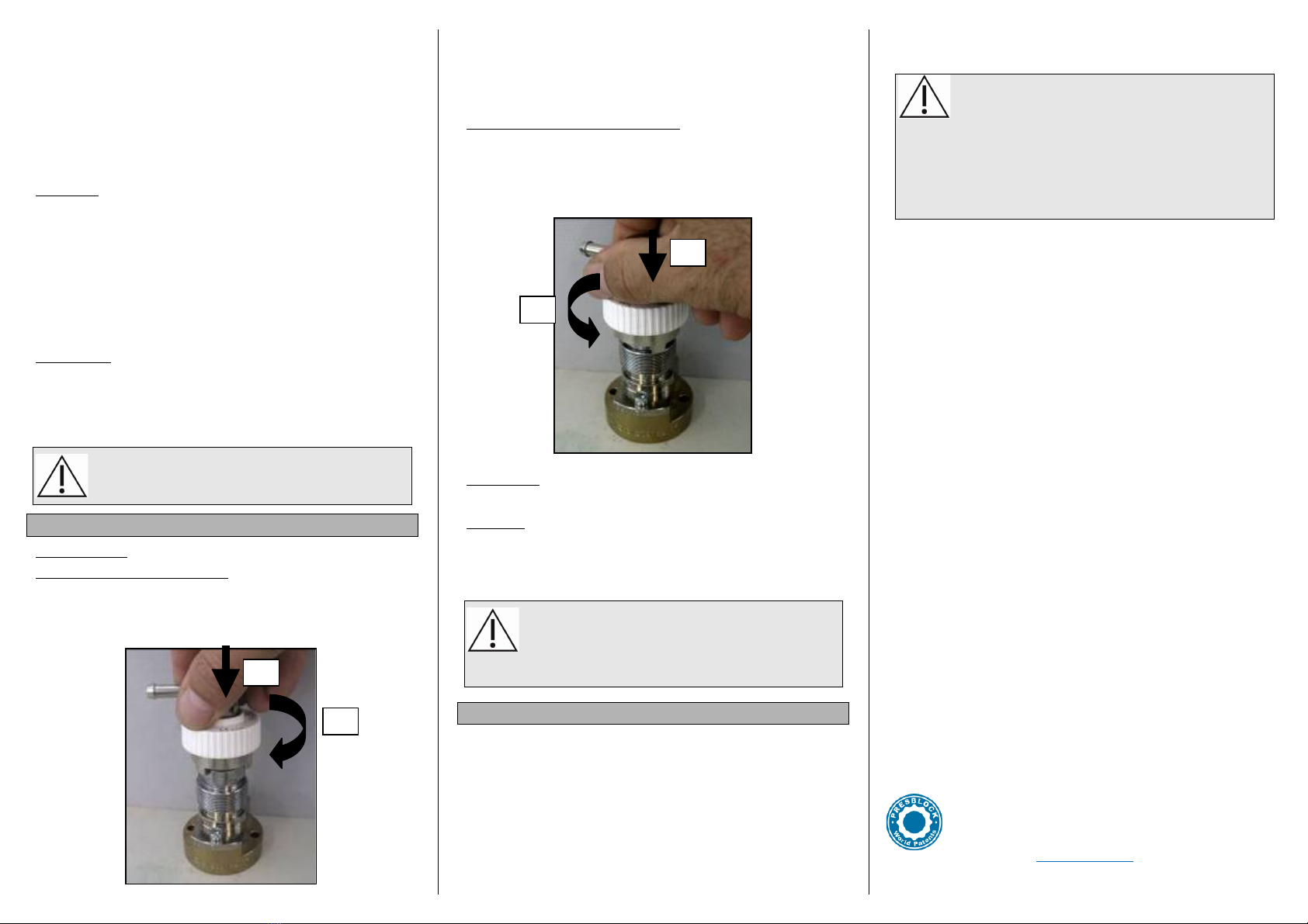
SOCKET / PROBE DISCONNECTION
1. Keep the probe, in order to prevent its quick projection;
2. Push the probe towards the base block with enough force to
oppose the upstream pressure;
3. Rotate anticlockwise the probe;
4. Pull out the probe from the socket.
4.2 Cleaning
For cleaning use only distilled water or diluted ethyl alcohol.
4.3 Safety
Before use, personnel must familiarize with the control devices and
their operations.
If the medical device is out of order or in maintenance, disconnect
the gas supply and place a visible sign stating “NOT IN SERVICE.
DO NOT USE”.
Do not use the medical device for gases or pressures
different from those for which it is designed.
Do not crash the probe, in order not to spoil its
functionality.
Do not try to insert probes designed for a different gas and/or
different standard into the sockets. This may damage both devices.
5. Maintenance
The maintenance program must envisage a minimum of biannual
inspections with particular reference to:
•easy coupling and disconnection;
•wear or damage;
•contamination;
•marking – labelling;
•tightness;
•flow rate according to EN ISO 7396-1.
These operations must be recorded.
The following maintenance kits are available for the sockets:
•VGTF-RIC (for all gases except VAC and AIR-800);
•VGTF-A8-RIC (only for AIR-800);
•VGTF-V-RIC (only for VAC).
Every precaution must be taken to maintain the
cleanliness according to the requests of EN ISO 15001
standard.
During maintenance and repair only original parts must be used.
Do not use lubricants that aren’t compatible with the distributed
gases at their operating pressures. Especially in the case of contact
with oxygen there might be safety issues relating to fire or
explosion, if an incompatible lubricant is used.
Once maintenance is completed, testing required by EN ISO 7396-
1 standard must be run again
PRES BLOCK S.p.A.
via Alpignano 151-155 – I-10040 Caselette (TO) - Italy
Ph: 0039-011-9688055 - Fax : 0039-011-9688668
www.presblock.com
FTGTF05e Rev.6 dated 2017-05
3°
4°
2°
3°
This manual suits for next models
1


