Abtus ABT4650 RouteScan User manual

4650-1 Issue 04
ABT4650
RouteScan
Instruction Manual

4650-1 Issue 04
1
1.0Index
1.0 Index 1
2.0 Item List 2
3.0 Specification 2
4.0 Getting Started 3
4.1 Overview 3
4.2 Assembly 4
4.3 Bluetooth Connection 4
4.4 Single Point Measurement 6
4.5 Recording Data 7
5.0 Software Features 9
5.1 Settings 9
5.2 View Results 9
5.3 File Types 10
5.4 Transferring Recorded Data Files to a PC 10
6.0 Target Pole 11
7.0 Maintenance 13
7.1 Before Each Use 13
7.2 Every 3 Months 13
7.3 Annual 13
8.0 Measurement Characteristics 14
8.1 Point Co-ordinates 14
8.2 Gauge 14
8.3 Super-Elevation 14
9.0 Trouble shooter 15
9.1 Tips for Good Recording 15
9.2 No Power 15
9.3 Cannot Connect 15
9.4 Cannot Save Data 15
9.5 Measurement Takes a Long Time 15

2
4650-1 Issue 04
2.0Item List
1. RouteScan
2. Control Unit
3. Carry Case
4. Instruction Manual
5. RouteScan Charger
6. Control Unit Charger
7. Optical Cleaning Kit
8. Target Pole (if purchased separately)
3.0Specification
Weight
-
-
-
On track(RouteScan)
(Control Unit)
In Box
9.5kg
0.2kg
25kg
Physical Dimensions
-
-On Track(RouteScan)
In Box 1655 x 250 x190 mm
Length:1755 mm
Height:373 mm
Width:385 mm
Operating
Temperature - -10°C to + 50°C (-4°F to 122°F)
Environmental
Rating - IP54
Battery Life
-
-RouteScan
Control Unit Up to 6 hours
Up to 6 hours
Operating System -
PC Connectivity - USB
Bluetooth
Wireless LAN

4650-1 Issue 04
3
4.0Getting Started
4.1 Overview
The RouteScan has been developed to provide quick, accurate structure
clearance measurements relative to the Permanent Way. With the RouteScan in
position on the track, the operator is able to control, from a position of safety, the
measurement laser using the Control Unit via a Bluetooth connection.
The unit is a lightweight (9.5kg) and is provided with a protective box for easy
transportation to and from site. All data is shown on a colour screen and is stored
on an SD Memory Card for easy transfer to a PC, where the files can be opened
and viewed in MS Excel.
The use of wireless technology in the RouteScan means that there are two
separate batteries in the ABT4650:
•RouteScan
•Control Unit
The unit has been designed to be user-friendly with only limited training required.
RouteScan is approved for use in the UK in areas of 3rd rail. The following
guidelines should be adhered to when using RouteScan in an area of live 3rd rail:
1. Never touch any part of RouteScan against the electrified 3rd rail
2. When carrying RouteScan on the track, take extra care to avoid tripping.
Carry RouteScan on the opposite side of your body to the 3rd rail
3. When lifting RouteScan on or off the rail, ensure you have a firm footing
and that you are standing between the running rails
4. When pointing the laser dot at a specific point, never place yourself or
others in a position of danger. Wherever possible, control the position of
the laser dot using the PDA from a safe position
Before Use:
Make sure there are no stains or marks on the optical window and
that the optical window is NEVER touched directly.
For cleaning instructions see Section 7.1
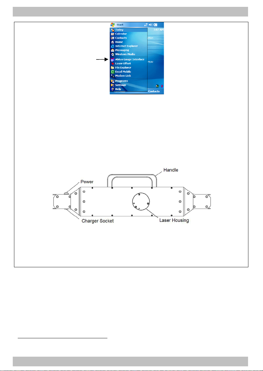
RouteScan produces a visible (635nm wavelength) laser beam which emerges
from the Laser Housing (Figure 2)

4
4650-1 Issue 04
It is a Class II laser product in accordance with:
1) IEC60825-1 (2001) “Radiation safety of laser products”
2) EN60825-1 (2001) “Radiation safety of laser products”
3) FDA 21 CFR 1040.10 and 1040.11 (US department of health and human
service, Code of federal Regulations)
Laser Class II products:
Do not stare into the laser beam or direct it towards other people unnecessarily.
Eye protection is normally afforded by aversion responses including the blink
reflex.
CAUTION
Looking into the laser beam may be hazardous to the eyes.
Laser may turn on without warning.
Do not allow water droplets to fall on the lens of the laser housing as this may
compromise accuracy. If water does drop on the lens, carefully blot away using
the lens tissue provided. Follow the instructions in Section 7.1 to clean the lens if
necessary.
Please review Section 9.1 prior to using your ABT4650 for the first time.
4.2 Assembly
Upon receipt of your ABT4650 no assembly is required.
4.3 Bluetooth Connection
Before recording can start, a Bluetooth connection must be made between the
Control Unit and the ABT4650 – imagine this step is like plugging in the cable:
1. Turn on the Control Unit (Please refer to manufacturers own operating
manual for details of operation as Control Unit models may vary) – wait
until the Windows operating system has fully loaded
2. Load the Abtus Gauge Interface software from the Start Menu (as shown
in Figure 1) – the software launches directly to the ‘Connection’ screen

4650-1 Issue 04
5
Figure 1
3. Ensure that the gauge is powered by pressing the Power Button – the
Power Button should now display a green light (Figure 2).
N.B. Once the Power Button has been pressed, RouteScan goes through
a start-up period – it is not possible to turn off RouteScan until start-up is
complete. During start-up the Laser Housing will rotate as part of a self-
calibration routine; do not interfere with it during this period.
Figure 2
4. Select the desired gauge from the list1and click the ‘Connect’ button
5. Please be patient while the Control Unit makes the connection
6. When the connection has been made, the ‘Options’ screen is displayed
(Figure 3)
1The Abtus Gauge Interface software is common to all Abtus Bluetooth products and so it is possible
to ‘Pair’ the Control Unit with a number of different gauges

6
4650-1 Issue 04
Figure 3
7. If the connection fails see Section 9.3 for help
8. Rotate the black lens cover to reveal the optical lens before attempting to
take any readings (Figure 4)
Figure 4
4.4 Single Point Measurement
To make a single point measurement:
1. Select ‘Single Point’ from the ‘Options’ screen (Figure 3) – this will display
the ‘Single Point’ screen (Figure 5)
2. The position of the laser beam can now be controlled either by rotating
the laser housing by hand
or
by sliding the Rotate bar left/right on the Control Unit. When the laser
beam is in the desired position, return the Rotate bar marker back to the
centre position
3. The laser can be returned to Zero by clicking ‘Zero’. The laser returns to
either an absolute or a relative zero depending on the status of the
‘Absolute’ tick box
4. To take an offset measurement, click the ‘Measure’ button
•An absolute or relative reading can be selected by ticking or un-

4650-1 Issue 04
7
ticking the ‘Absolute’ tick box
•Tick the ‘Target Pole’ tick box to measure to a point using the target
pole2
Figure 5
Note – it is not possible to send commands from the Control Unit when the
Laser Housing is rotating. Ensure that the Laser Housing is stationary
before clicking any buttons or closing a window.
4.5 Recording Data
Profile:
1. The parameters used when recording a profile are set in the ‘Settings’
Menu – see Section 5.1
2. Select ‘Start Recording’ from the ‘Options’ screen (Figure 1)
3. Select ‘Profile’ from the next menu (Figure 6) – note that it is also
possible to add a series of Single Point measurements to a profile
recording
Figure 6
4. In the ‘Session Details’ screen, enter a file name. A start description
2See section 6.0 for more details.

8
4650-1 Issue 04
can be added by selecting ‘More’. Hide the keypad and select ‘Start
Recording’
5. When ready, select ’Start’ to begin the scanning process. The Laser
Housing unit will begin to rotate and after a short period
measurement data will begin to appear on the display. The scan is
automatically broken up into sections. Scanned data is displayed on
the Control Unit after each section has been scanned. By clicking
‘Cancel’ it is possible to stop the scan at any time; the scan will stop
after it has completed the current section
6. When the scan is complete, the laser will switch off and the Laser
Housing will rotate back to its Zero position
7. The profile can now be saved or re-measured – to insert additional
points click ‘Single Point’. Position the laser (see Section 4.4) and
click ‘Measure’. See below for more information on this step
Single Point
1. Select ‘Start Recording’ from the ‘Options’ screen (Figure 1)
2. Select ‘Single Point’ from the next menu (Figure 6)
3. Control the laser as described in section
4. Click ‘Measure’ – select ‘Save Point’ to confirm the measurement – a note
can now be added against this point
5. After adding a note, hide the keypad and click ‘Save Point’ again.
Note – it is not possible to send commands, other than ‘Cancel’, from the
Control Unit when the Laser Housing is rotating. Ensure that the Laser
Housing is stationary before clicking any other buttons or closing a
window.

4650-1 Issue 04
9
5.0Software Features
5.1 Settings
Within the settings page (Figure 7) it is possible to create/edit any number of scan
parameter sets. The parameters in each set define how a scan is performed:
•Start Angle
•End Angle
•Increment (Resolution)
•Absolute/Relative
Predefined settings can be selected to suit the structure being scanned
1. Select ‘Settings’ from the options screen (Figure 1)
2. To create a new set of parameters, select ‘Create Profile’ from the
Settings Profile drop down menu. ‘New profile’ will now be displayed, click
and hold this in order to rename it
3. Click inside the corresponding box to change the various parameters –
use the keypad to do this
4. If a Bluetooth connection to the RouteScan exists, it is possible to set the
Start and End Angle visually:
•Click and hold in either the ‘Start Angle’ or ‘End Angle box
•Click ‘Turn Laser On’
•Point the laser at the desired point
•Click ‘Select ‘Angle’
5. An absolute or relative reading can be selected by ticking or un-ticking the
Absolute tick box
Figure 7
5.2 View Results
To review recorded Data Files click the ‘View Results’ button in the ‘Options’
screen. Select the file you wish to review from the drop down box at the bottom of
the screen. Toggle between file types (see section 5.3) using the button in the
bottom right of the screen.

10
4650-1 Issue 04
5.3 File Types
The ABT 4650 automatically saves two files for each recording. The file types are:
•*.csv
•*.sec
The CSV file is in a standard format which will open in almost any software
package (e.g. Excel, Word, Notepad etc). This file contains all the Start and Finish
information along with all the recorded data in an easy to read layout.
The SEC file contains exactly the same information as the CSV file but is
encrypted. It is only possible to view this ‘secure’ file through the ‘View Results’
screen (see section 5.2) however it is not possible to edit it. This file is tamper-
proof and is suitable for auditing purposes.
5.4 Transferring Recorded Data Files to a PC
Recorded Data is stored on the control unit in the following location:
\\SD Card\Abtus Gauge Interface\Recorded Data\RouteScan\....
Data can be transferred in one of two ways:
ActiveSync
1. Connect the control unit to the PC using either a USB cable or a
Bluetooth connection
2. Open Windows Explorer on the PC and in My Computer, select Mobile
Device
3. Navigate to the above location and copy the Data Files as required
(Depending on the PC’s Operating System, the PC may try to download
ActiveSync from the internet when it has sensed the connection between the
Control Unit and the PC – follow the on-screen instructions to complete this step)
SD Card Reader
1. Remove the SD card from the control unit (always power down the control
unit before removing the SD card) and insert it into the PC
2. Navigate to the above location on your PC using Windows Explorer and
copy the Data Files as required
Abtus Ltd can supply SD Card readers that connect to a USB port.

4650-1 Issue 04
11
6.0Target Pole
The target pole is an optional accessory for RouteScan. It allows the
measurement of points that cannot be ‘seen’ directly by the laser, such as the
gauge corner of the rail on an adjacent track.
It is comprised of:
•Target Pole
•Rail Pole
•Pointed Foot
•Rounded Foot
Figure 8
To measure a point using the target pole, load the Single Point screen and tick
the ‘Target Pole’ tick box. The software will automatically adjust the measurement
by the vertical height of the target.
When measuring to the Target Pole:
•Ensure that the target surface is ‘square’ to the laser
•Check that it is held vertically by using the bubble embedded in the top of
the pole – a 1mm offset of the bubble from the centre of the vial
translates approximately to a 0.5mm error in the X-Y measurement

12
4650-1 Issue 04
The Pointed Foot and Rounded Foot click into the bottom of the Target Pole and
are interchangeable. When using the Target Pole on its own, it is advisable to use
the Rounded Foot to minimise wear to the Pointed Foot (refer to Section 7.2).
When using the Target Pole with the Rail Pole, the Pointed Foot must be fitted.
When measuring the location of an adjacent track, the Rail Pole allows the
Pointed Foot to be located accurately on the gauge corner of the rail.
1. Place the Rail Pole on the track to be measured
2. Ensure that the Rail Pole is located ‘squarely’ across the track and that it
is firmly located against the rail being measured
3. Locate the Pointed Foot in the socket in the Rail Pole

4650-1 Issue 04
13
7.0Maintenance
7.1 Before Each Use
Make sure there are no stains, marks or dirt on the lens. After blowing off dirt and
dust, the drag method can be used to remove fingerprints or other contaminants
The lens is of an extremely high grade and is coated with a proprietary
compound. Unlike many other optical coatings of this grade, this compound is
tough enough to be cleaned using the lens tissues and cleaning solution
provided. However, each clean detracts from the life time of the coating and so
direct contact cleaning should be kept to a minimum.
NEVER touch the lens with anything other than the lens tissues provided
NEVER use high pressure air to remove dirt/dust from the lens
NEVER use a circular motion to clean the lens
7.2 Every 3 Months
Visually inspect the ABT4650 for signs of damage. If necessary, contact your
local distributor for help.
If using the Target Pole accessory, check the Pointed Foot and Rounded Foot for
wear by measuring the length as shown in Figure 9. The foot should be replaced
if it has worn by more than 1mm.
Figure 9
7.3 Annual
The ABT4650 is approved for use in the UK in areas of 3rd rail. An annual
electrical insulation test should be carried out.
The ABT4650 must be returned to Abtus Ltd annually for re-calibration to ensure
measurements are within specification. The ABT4650 will also be tested for
electrical insulation compliance at the same time. If using the Target Pole
accessory, this should be re-calibrated at the same time.
The condition of all components will be checked at this time and replaced as
required.

14
4650-1 Issue 04
8.0Measurement Characteristics
8.1 Point Co-ordinates
Range 0.2-30m
Accuracy ±3mm @ 4.0m
±6mm @ 8.0m
Resolution 1mm
8.2 Gauge
Range -15/+25mm (on nominal)
Accuracy ±0.5mm
Resolution 0.1mm
8.3 Super-Elevation
Range ±200mm
Accuracy ±1.2mm
Resolution 0.1mm
Super Elevation (SE) is measured across the running rails and is displayed as
height differential between the high and low rail in millimetres
- ive SE is the right rail lower than the left rail
+ ive SE is the right rail higher than the left rail
NB. The left end is the fixed end of the gauge

4650-1 Issue 04
15
9.0Trouble shooter
9.1 Tips for Good Recording
The ABT4650 is a very accurate piece of equipment – many of the parameters
that it measures rely on extremely sensitive sensors. While every reasonable
effort has been made to make it ‘railway proof’, users should treat it with extreme
care.
9.2 No Power
Check that all the batteries are fully charged. The RouteScan takes approximately
4hours to charge and the Control Unit takes approximately 2hours.
9.3 Cannot Connect
The connection between the Control Unit and the RouteScan is via Bluetooth.
Obstacles such as metal and water (the human body is mostly water!) can
degrade wireless signals – ensure that nothing is restricting the signal.
Ensure that all batteries are fully charged (see Section 4.1 for more information
on the batteries).
9.4 Cannot Save Data
Check that the SD Card is not set to ‘Read-Only’ (the small white switch on the
side of the card).
9.5 Measurement Takes a Long Time
The time taken to perform a point measurement is dependant on surface quality.
Surfaces that are too shiny or too dull will effect the measurement time. On
standard brickwork or masonry, RouteScan can complete up to 240
measurements per second.
RouteScan has been benchmarked on the same calibration surface as is used for
calibrating the Structure Gauging Train in the UK and has been proven to work
reliably.
When using RouteScan to measure Gauge and SE in Single Point mode; ensure
that the laser is pointing at a near-by surface to minimise measurement time.
Other manuals for ABT4650 RouteScan
1
Table of contents
Other Abtus Measuring Instrument manuals

Abtus
Abtus ABT-7000 User manual

Abtus
Abtus ABT 4610 Laser Offset Gauge User manual

Abtus
Abtus IFP-600 User manual

Abtus
Abtus ABT 4550 Series User manual

Abtus
Abtus ABT4640 User manual

Abtus
Abtus ABT4050 User manual

Abtus
Abtus ABT-7100 User manual

Abtus
Abtus ABT4650 RouteScan User manual

Abtus
Abtus ABT4659 User manual

Abtus
Abtus ABT5210 Ri59 User manual
Popular Measuring Instrument manuals by other brands

Dinel
Dinel CLM-36-10 instruction manual

ABB
ABB C1900 Series installation guide

Garmin
Garmin Approach Z80 owner's manual

Agilent Technologies
Agilent Technologies E5070A ENA Series Installation and quick start guide

Fema
Fema M40 Series user manual

Danaher Precision Systems
Danaher Precision Systems DPS BDM-6 manual