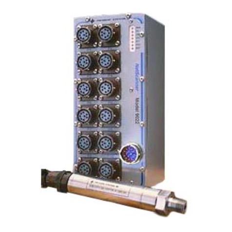
Pressure Systems NetScanner 9116 User manual

Model 9116
Intelligent Pressure Scanner
User’s Manual
August 2007
NetScanner™ System
www.PressureSystems.com

Pressure Systems, Inc. Model 9116 User’s Manual
Page i www.PressureSystems.com
REVISION REVISION HISTORY PRINT DATE
1 Updated manual terminology and deleted all
references to UDP Query and to O-ring part
numbers.
April 2004
2 Update terminology November 2004
3 Update commands August 2007
©This User’s Manual is a copyright product of Pressure Systems, Inc. , 2007.
Permission is hereby granted to make copies and distribute verbatim copies of this manual,
provided the copyright notice and this permission notice are preserved on all copies.

Pressure Systems, Inc. Model 9116 User’s Manual
Page ii www.PressureSystems.com
Table of Contents
Chapter 1: General Information ...........................................................................................1
1.1 Introduction ..............................................................................................................1
1.2 Description of the Instrument .......................................................................................2
1.2.1 Differences Between Models 9016 and 9116...................................................3
1.3 Options.........................................................................................................................5
1.3.1 Pressure Ranges..............................................................................................5
1.3.2 Manifolds and Pressure Connections...............................................................5
1.3.3 Communication Interfaces................................................................................6
Chapter 2: Installation and Set Up ......................................................................................7
2.1 Unpacking and Inspection............................................................................................7
2.2 Safety Considerations .................................................................................................. 7
2.3 Preparation for Use ......................................................................................................7
2.3.1 Environment ..................................................................................................... 7
2.3.2 Power ...............................................................................................................8
2.3.3 Mounting and Module Dimensions ................................................................... 9
2.3.4 Network Communications Hookup ................................................................... 9
2.3.4.1 Ethernet Host Port Hookup................................................................ 9
2.3.5 Diagnostic Port Hookup.................................................................................... 13
2.3.6 Pressure Connections ...................................................................................... 13
2.3.6.1 RUN Mode Inputs .............................................................................. 14
2.3.6.2 CAL Mode Inputs...............................................................................15
2.3.6.3 PURGE Mode Inputs ......................................................................... 15
2.3.6.4 LEAK Mode Inputs............................................................................. 16
2.3.6.5 Supply Air ..........................................................................................16
2.3.7 Case Grounding ............................................................................................... 17
2.3.8 Trigger Input Signal ..........................................................................................17
2.3.9 Power Up Checks and Self-Diagnostics...........................................................17
Chapter 3: Programming and Operation ............................................................................18
3.1 Commands & Responses ............................................................................................18
3.1.1 Introduction.......................................................................................................18
3.1.1.1 TCP/UDP/IP Protocols....................................................................... 18
3.1.2 Commands .......................................................................................................19
3.1.2.1 General Command Format ................................................................ 19
3.1.2.2 Command Field .................................................................................20
3.1.2.3 Position Field .....................................................................................20
3.1.2.4 Datum Fields......................................................................................21
3.1.2.5 Format Field.......................................................................................21

Pressure Systems, Inc. Model 9116 User’s Manual
Page iii www.PressureSystems.com
Table of Contents (continued)
3.1.3 Responses .......................................................................................................22
3.1.3.1 Interpreting Offset Values (Re-zero Calibration Adjustment)............. 23
3.1.3.2 Interpreting Gain Values (Span Calibration Adjustment) ...................23
3.1.3.3 Interpreting Engineering Units Output ............................................... 23
3.1.4 Functional Command Overview ....................................................................... 23
3.1.4.1 Startup Initialization ...........................................................................24
3.1.4.2 Module Data Acquisition....................................................................24
3.1.4.3 Calibration Adjustment of Offset/Gain Correction Coefficients ..........25
3.1.4.4 Delivery of Acquired Data to Host...................................................... 26
3.1.4.5 Network Query and Control Functions............................................... 27
3.1.4.6 Other Functions .................................................................................27
3.2 Detailed Command Description Reference.................................................................. 28
TCP/IP Commands
Power Up Clear (Command ‘A’) ....................................................................... 29
Reset (Command ‘B’) ....................................................................................... 30
Configure/Control Multi-point Calibration (Command ‘C’) ................................31
Sub-command Index 00: Configure & Start Multi-Point Calibration..............32
Sub-command Index 01: Collect Data for a Calibration Point ...................... 34
Sub-command Index 02: Calculate & Apply Correction Coefficients............ 36
Sub-command Index 03: Abort Multi-Point Calibration................................. 38
Read Tranducer Voltages (Command ‘V’)........................................................39
Calculate and Set Gains (Command ‘Z’).......................................................... 41
Read Transducer A/D Counts (Command ‘a’).................................................. 43
Read High-Speed Data (Command ‘b’)............................................................ 45
Define/Control Autonomous Host Streams (Command ‘c’) ..............................46
Sub-command Index 00: Configure a Host Delivery Stream........................48
Sub-command Index 01: Start Streams(s) ...................................................52
Sub-command Index 02: Stop Stream(s) .....................................................54
Sub-command Index 03: Clear Stream(s) .................................................... 55
Sub-command Index 04: Return Stream Information ................................... 56
Sub-command Index 05: Select Data in a Stream ....................................... 58
Sub-command Index 06: Select Protocol for Stream Delivery ..................... 61
Calculate and Set Offsets (Command ‘h’) ........................................................ 63
Read Temperature Counts (Command ‘m’) ..................................................... 65
Read Temperature Voltages (Command ‘n’).................................................... 67
Read Module Status (Command ‘q’) ................................................................69
Read High-Precision Data (Command ‘r’) ........................................................ 72
Read Transducer Temperature (Command ‘t’)................................................. 74
Read Internal Coefficients (Command ‘u’)........................................................76
Download Internal Coefficients (Command ‘v’) ................................................ 80
Set/Do Operating Options/Functions (Command ‘w’).......................................83
UDP/IP Commands
Network Query (UDP/IP Command ‘psi9000’) .................................................87
Re-Boot Module (UDP/IP Command ‘psireboot’) .............................................89
Change Module’s IP Address Resolution Method & Re-Boot
(UDP/IP Command ‘psirarp’) ............................................................. 90

Pressure Systems, Inc. Model 9116 User’s Manual
Page iv www.PressureSystems.com
Table of Contents (continued)
Chapter 4: Calibration ...........................................................................................................91
4.1 Introduction ..................................................................................................................91
4.2 Re-Zero Calibration......................................................................................................93
4.2.1 Re-Zero Calibration Valve Control....................................................................93
4.2.2 Re-Zero Calibration Summary.......................................................................... 94
4.3 Span Calibration...........................................................................................................94
4.3.1 Span Calibration Valve Control ........................................................................ 95
4.3.2 Span Calibration Summary ..............................................................................96
4.4 Integrated Multi-Point Calibration Adjustment.............................................................. 98
4.4.1 Multi-Point Calibration Valve Control................................................................98
4.4.2 Multi-Point Calibration Summary ...................................................................... 99
4.5 Coefficient Storage....................................................................................................... 100
4.6 Line Pressure Precautions ...........................................................................................101
Chapter 5: Service .................................................................................................................102
5.1 Maintenance.................................................................................................................102
5.1.1 Common Maintenance ..................................................................................... 104
5.1.2 Module Disassembly ........................................................................................ 105
5.1.3 Electronic Circuit Board Replacement..............................................................105
5.1.3.1 PC-327 Analog Board .........................................................................106
5.1.3.2 PC-322/323 Main Board/Power PC Daughter Board Assembly..........106
5.1.3.3 Remove and Replace PC-323 on PC-322........................................... 108
5.1.4 Replacement of Transducers ........................................................................... 109
5.1.5 Calibration Valve Solenoid Replacement ......................................................... 110
5.1.6 Replacement of O-Rings .................................................................................. 111
5.1.6.1 DH200 Pressure Transducer O-Ring Replacement ............................ 112
5.1.6.2 Tubing Plate O-Ring Replacement...................................................... 113
5.1.6.3 Adapter Plate O-Ring Replacement .................................................... 114
5.1.6.4 Calibration Manifold Piston O-Ring Replacement ............................... 115
5.1.6.5 Solenoid Valve O-Ring Replacement .................................................. 116
5.2 Upgrading Module Firmware........................................................................................ 117
5.2.1 Upgrading Firmware Via Host TCP/IP Port ...................................................... 117

Pressure Systems, Inc. Model 9116 User’s Manual
Page v www.PressureSystems.com
Table of Contents (continued)
Chapter 6: Troubleshooting Guide......................................................................................118
6.1 Ethernet Module Troubleshooting ................................................................................118
6.1.1 Checking Module Power-Up Sequence............................................................118
6.1.2 Checking Module TCP/IP Communications .....................................................119
6.1.2.1 Module IP Address Assignment .......................................................... 119
6.1.2.2 Host IP Address Assignment for Windows® 95/98/2000/XP/NT......... 120
6.1.2.3 Verifying Host TCP/IP Communications.............................................. 121
6.2 Zero and Gain Calibration Troubleshooting ................................................................. 122
6.3 User Software ..............................................................................................................123
Chapter 7: Start-up Software ................................................................................................ 124
7.1 Introduction ..................................................................................................................124
Appendices:
Appendix A: All Commands – Quick Reference .....................................................................125
Appendix B: Model 9116 Response Error Codes ................................................................... 126
Appendix C: Cable Diagrams.................................................................................................. 127
Appendix D: 9116 Mounting Dimensions................................................................................ 129
Appendix E: Model 9116 Range Codes.................................................................................. 130
Appendix F: NetScannerAppendix D: 9116 Mounting Dimensions........................................ 132
Appendix G: Binary Bit Map....................................................................................................133

Pressure Systems, Inc. Model 9116 User’s Manual
Page vi www.PressureSystems.com
Preface
This manual describes the NetScanner™System Intelligent Pressure Scanner module (Model
9116). It does not cover the pressure scanner Models 9016, 9021, 9022, the 98RK Scanner
Interface Rack, Model 9816 Intelligent Pressure Scanner, nor Models 903x (Pressure
Standards/Controllers. These products are covered in their individual User’s Manuals.
This manual is divided into six (6) chapters and several appendices, each covering a specific
topic. They are summarized below:
Chapter 1: General Information describes Model 9116 Intelligent Pressure
Scanner and its various options.
Chapter 2: Installation and Set Up describes the unpacking and inspection of a
module, and its connection to power, pressure,
and a communications network.
Chapter 3: Programming & Operation provides the information needed to program a
module from a host computer and to get
meaningful data from it.
Chapter 4: Calibration describes methods of calibrating a module.
Chapter 5: Service describes general safety precautions and
maintenance procedures.
Chapter 6: Troubleshooting describes module troubleshooting techniques.
Chapter 7: Start-up Software briefly describes NUSS software.
Appendix A: All Commands — Quick Reference
Appendix B: Response Error Codes
Appendix C: Cable Diagrams
Appendix D: Module Mounting Dimensions
Appendix E: NetScanner System Range Codes
Appendix F: NetScanner™System Products
Appendix G: Binary Bit Map

Pressure Systems, Inc. Model 9116 User’s Manual
Page vii www.PressureSystems.com
Our Company
Pressure Systems Incorporated, (PSI) develops, manufactures, and services level and pressure
measuring instruments where the highest level of traceable accuracy is required for aerospace,
industrial, municipal, and environmental applications. Our products have become the world
standard for electronic level and pressure measurement and scanning. We are committed to
the highest quality design, manufacture, and support of level and pressure instrumentation that
is in the best interest of our customers. PSI is an ISO-9001:2000 certified company.
Our Warranty
Pressure Systems, Inc., warrants NetScanner™System products to be free of defects in
material and workmanship under normal use and service for one (1) year.
Technical Support
Monday through Friday, during normal working hours, (7:30 am through 5:30 pm, Eastern time)
knowledgeable personnel are available for assistance and troubleshooting. Contact the
Applications Support Group or the Customer Services Department at Pressure Systems
(757-865-1243 or toll free 1-800-328-3665) if your scanner is not operating properly or if you
have questions concerning any of our products. E-mail assistance is available by contacting
Merchandise Return Procedures
If your scanner needs to be returned to Pressure Systems, obtain a Returned Merchandise
Authorization (RMA) from the Customer Service Department.
Be prepared to supply the following information when requesting the RMA:
•Part number
•Serial number
•Complete description of problems/symptoms
•Bill To and Ship To address
•Purchase order number (not required by PSI warranty repairs)
•Customer contact and telephone number
The above information, including the RMA number must be on the customer’s shipping
documents that accompany the equipment to be repaired. PSI also requests that the outside of
the shipping container be labeled with the RMA number to assist in tracking the repairs. All
equipment should be sent to the following address:
ATTN: PSI REPAIR DEPARTMENT (7-digit RMA number)
Pressure Systems, Inc.
34 Research Drive
Hampton, Virginia 23666

Pressure Systems, Inc. Model 9116 User’s Manual
Page viii www.PressureSystems.com
PSI will return warranty items prepaid via UPS GROUND. If the customer desires another
method of return shipment, PSI will prepay and add the shipping charges to the repair bill.
Incoming freight charges are the customer’s responsibility. The customer is also responsible for
paying shipping charges to and from PSI for any equipment not under warranty.
All products covered under the PSI warranty policy will be repaired at no charge. An analysis
fee will be charged to quote the cost of repairing any item not under warranty. If, for any
reason, the customer decides not to have the item repaired, the analysis fee will still be
charged. If the quote is approved by the customer, the analysis fee will be waived. The quote
for repair will be based on the PSI flat rate for repair, calibration, and board replacement. When
these prices do not apply, the quote will be based on an hourly labor rate plus parts. All
replaced parts are warranted for 90 days from the date of shipment. The 90-day warranty is
strictly limited to parts replaced during the repair.
Website and E-Mail
Visit our website at www.PressureSystems.com to look at our new product releases, application
notes, product certifications, and specifications. E-mail your questions and comments to us:
Our Firmware
This manual was prepared for various versions of module firmware as were released at
the time of this manual publication. Addenda will be distributed as deemed necessary
by PSI. Any questions regarding firmware upgrades may be addressed to the
Applications Support Group. Firmware revisions, manual addenda, and utility
software may also be obtained from the PSI web page at www.PressureSystems.com.
Our Publication Disclaimer
This document is thoroughly edited and is believed to be thoroughly reliable. Pressure
Systems, Inc., assumes no liability for inaccuracies. All computer programs supplied
with your products are written and tested on available systems at the factory. PSI
assumes no responsibility for other computers, languages, or operating systems. PSI
reserves the right to change the specifications without notice.

Pressure Systems, Inc. Model 9116 User’s Manual
Page 1 www.PressureSystems.com
Chapter 1
General Information
1.1 Introduction
This User’s Manual will:
!Explain the electrical and pneumatic pressure connections for the Model 9116 Intelligent
Pressure Scanner.
!Provide computer set-up instructions to make a proper Ethernet connection on most
Windows®95/98/XP/NT-based personal computers.
!Instruct you on using the PSI start-up software to manipulate and acquire data from each
module.
!Instruct you on how to program each module with computer software.
Model 9116 is a pneumatic Intelligent Pressure Scanner, with integral pressure transducers and
a pneumatic calibration manifold.
The Model 9116 provides engineering unit pressure data with guaranteed system accuracy.
This is achieved by reading factory-determined pressure and temperature engineering-unit data
conversion coefficients from its transducers’ nonvolatile memories at power-up. It also allows
additional adjustment coefficients to be “fine-tuned” with a multi-point calibration under host
control (e.g., possibly utilizing optional Pressure Systems 903x Pressure Calibrator modules).
Model 9116 provides an auto-configuring 10BaseT/100BaseT Ethernet communications port.
Half duplex/full duplex operation is also automatically configured. The Model 9116
communicates using the TCP/UDP/IP protocols.
The Model 9116 Intelligent Pressure Scanner is a component of a networked data acquisition
concept called the NetScanner™ System. Multiple NetScanner modules measuring a wide
variety of parameters can be networked to form a distributed intelligent data acquisition system.

Pressure Systems, Inc. Model 9116 User’s Manual
Page 2 www.PressureSystems.com
Figure 1.1
Model 9116 Intelligent Pressure Scanner
1.2 Description of the Instrument
The Model 9116 is available with16 channels, each with individual pneumatic transducers per
channel. The most distinctive features are highlighted below:
●Pre-calibrated Transducer - a memory chip containing full calibration data is embedded
within each internal transducer.
●Individual transducer per measurement input channel - mixed transducer ranges may
be installed in a single Model 9116 module.
●Low cost per point - per-channel cost is less than a typical industrial pressure
transducer/transmitter.

Pressure Systems, Inc. Model 9116 User’s Manual
Page 3 www.PressureSystems.com
●High accuracy - Model 9116 pressure scanners are capable of accuracies up to
±0.05%. Accuracy is maintained through use of built-in re-zero, span, or multi-point
calibration capabilities. Accuracies are maintained for six (6) months after calibration.
●Low thermal errors - each internal transducer contains an individual
temperature sensor and thermal calibration data for internal use by software
correction algorithms. Thermal errors are reduced as low as ±0.001%FS/ºC over
the calibrated temperature span.
●Re-zero upon demand - an integrated calibration valve allows for automatic re-
zero adjustment calibration of dry gas transducers to null offset drift errors.
●Ease of transducer replacement - factory calibrated transducer assemblies may
be stocked and rapidly replaced in the field. Storage of thermal coefficients
within the transducer allows for ‘plug and play’ transducer replacement.
●Ease of calibration - each Model 9116 module contains a pneumatic
calibration manifold and software commands to automatically perform re-zero,
span, and multi-point adjustment calibrations. New offset and gain coefficients
that result from the most recent calibration may be stored in non-volatile
transducer memory.
●Ease of use - modules have simple command sets and provide engineering units
output. They may interface directly to a desktop or laptop computer or they may
be interconnected into a large network controlled by many types of host
computers.
●Connectivity - use of industry-standard communications network protocols to
control and read data from NetScanner™System modules allows distribution to
the point of measurement and ensures compatibility with third party hardware
and software.
1.2.1 Differences Between Models 9016 and 9116
The all new electronics of the Model 9116 reduces data acquisition noise and capture latency,
while actually improving channel settling time and boosting data throughput. Additionally, the
Ethernet interface has been upgraded to 10BaseT/100BaseT with half and full duplex
capabilities to provide significant flexibility in network configuration. The Ethernet interface is
completely auto-configuring, ensuring the best utilization of network capabilities, while ensuring
the maximum backward compatibility. The trigger circuitry has been upgraded to allow triggering
on positive, negative, or both transitions of the trigger signal. By configuring the Model 9116 to
trigger on both transitions, the Model 9116 can be integrated into existing systems, providing
twice the data throughput for most users, without modification to the system trigger circuit.
The firmware in the Model 9116 implements the Model 9016 command set further simplifying
use with existing systems. In fact, the Model 9116 can be configured to report its identity as a
Model 9016 to ensure compatibility with system software that is sensitive to the reported model
type.

Pressure Systems, Inc. Model 9116 User’s Manual
Page 4 www.PressureSystems.com
Consolidated below are the new commands added to the Model 9016 command set, as well as
differences in existing commands, command parameters, or command responses:
Set Module type alias: w3200 xxxx
See the ‘SET/DO OPTION/FUNCTIONS’ (command ‘w’)’ in Section 3.2.
Configures the Model 9116 to report its model type as Model 9116 or as a
Model 9016 for compatibility with model type sensitive system software.
Set Hardware Trigger Mode: w320x
See the ‘SET/DO OPTION/FUNCTIONS’ (command ‘w’)’ in Section 3.2.
Configures the trigger to response to positive going, negative going, or to
any transition on the trigger input.
Query the Hardware Trigger Mode: q32
See the ‘READ MODULE STATUS’ (command ‘q’)’ in Section 3.2.
The Model 9116 will respond with a 1, 2, or 3 indicating, respectively, that its
trigger is set to respond to a positive going, negative going or to any
transition on the trigger input. The Model 9016 will respond to this command
with an ‘N08’.
Query the Module Hardware Version: w31
See the ‘READ MODULE STATUS’ (command ‘q’)’ in Section 3.2.
The Model 9116 will report the version of hardware present as a floating
point number of the format x.xxxxxx The Model 9016 will respond to this
command with a ‘N08’.
Modifications to existing commands, (See Section 3.2):
In the ‘CONFIGURE A HOST DELIVERY STREAM’ (command ‘c’), the sync delay
can now be set as small as 2 milliseconds and the granularity is 2 milliseconds with
all other values rounded down to the nearest 2 milliseconds. This value was 10
milliseconds in the Model 9016.
In the Set Number of A/D Samples to Average, (command ‘w’). the minimum
value and the default value is 4. The interleaved instrumentation amplifiers utilized
in the Model 9116 allows it to provide the same throughput with one to four
averages. With the quieter electronics of the Model 9116 and no speed advantage
for lower numbers of averaged samples, the minimum and default is set to four.
Valid values are 4, 8, 16, 32, and 64. Other values below 64 are rounded up to the
next valid value listed above.”

Pressure Systems, Inc. Model 9116 User’s Manual
Page 5 www.PressureSystems.com
Additional enhancements to the Model 9116
Software Scan List Speeds:
Software Scan lists can be run as fast as hardware trigger scan lists on the
Model 9116 (~500 Hz. See specification sheet). The Model 9016 was
limited to 100 Hz maximum software trigger scan lists.
Firmware Updates/Boot Loader:
The firmware in the Model 9116 may be updated in situ, over its Ethernet
connection. This is the preferred method for updating the firmware and may
be invoked at any time. (See Section 5.2.1).
The user must connect to the updated module. Establishing a TCP/IP
connection is the last step in validating a successful firmware update. If the
unit is power-cycled four times without establishing a TCP/IP connection, the
firmware update will be tagged as invalid. The Model 9116 contains a
protected resident boot loader that will then take over operation of the
module. The resident boot loader resides in protected memory. It monitors
the state of the firmware and the operation of any downloads. Even in the
event of a power failure during a firmware update, upon return of power, the
resident boot loader will be available, and will establish communications for
downloading new firmware. The user can determine that the Model 9116 is
in boot loader mode by observing that the firmware version reported by the
module is less than 1.0 In boot loader mode, the Model 9116 will return an
‘N08’ in response to the ‘a’, ‘c’, ‘m’, ‘n’, ‘r’, and ‘t’ commands.
1.3 Options
1.3.1 Pressure Ranges
Model 9116 contains sixteen (16) DH200 transducers. These transducers are available with full
scale pressure ranges from 10" H2O (inches of water column) to 750 psid (2.5 kPa to 5200
kPa). Transducers with different pressure ranges may be combined in a single module.
Please consult the Sales Department at Pressure Systems for availability of other pressure
ranges (1-800-678-SCAN (7226)).
1.3.2 Manifolds and Pressure Connections
Model 9116 sixteen-channel Intelligent Pressure Scanners are available with a true differential
or common reference pneumatic manifold, and have a standard purge and leak check manifold.
They are available with standard 1/8" or optional 1/16" and 1/4" compression fittings. All fittings
utilize an SAE 5/16 - 24 O-ring boss which supports a variety of other adapter compression
fittings. They are also available with a quick disconnect plate which contains 0.063" bulge
tubulation. The common differential version is available with all choices of fittings. The true
differential version is available with 0.063" bulged tubulation fittings only.
Consult the Sales Department at Pressure Systems at 1-800-678-SCAN (7226) for availability of
other input fittings.

Pressure Systems, Inc. Model 9116 User’s Manual
Page 6 www.PressureSystems.com
1.3.3 Communication Interfaces
All standard NetScanner™System Intelligent Pressure Scanners provide temperature
compensated and linearized pressure data in engineering units via digital methods. They have a
10BaseT Ethernet host communications interface using industry standard TCP/IP or UDP/IP
protocol. This interface provides high data transfer rates and system connectivity. The Model
9116 adds auto-configuring 10BaseT/100BaseT, half duplex/full duplex capabilities for improved
network flexibility.

Pressure Systems, Inc. Model 9116 User’s Manual
Page 7 www.PressureSystems.com
Chapter 2
Installation and Set Up
2.1 Unpacking and Inspection
The NetScanner™System product family has many components which may be purchased
either as an entire system, or as individual pieces of equipment. Before assembling the system,
use the shipping bill as a reference to ensure that all parts have arrived. Pressure Systems
takes no responsibility for equipment that is damaged during shipment. If containers are
broken, ripped, or damaged, contact the transportation carrier. If the equipment itself appears
to be damaged, contact the Repair Department at Pressure Systems.
Each Model 9116 Intelligent Pressure Scanner shipment will contain the following minimum
components:
•Model 9116 Intelligent Pressure Scanner module
•Start-up software CD-ROM
•Model 9116 User’s Manual for Intelligent Pressure Scanners CD-ROM
2.2 Safety Considerations
It is always a good idea to wear safety glasses when operating this equipment or when working
with pressurized lines. Always ensure that high pressure lines are properly secured and that all
pneumatic lines are rated for the proper pressure and temperature environments.
All system power should be OFF during installation (or removal) of any components in a
NetScanner™System module. Failure to turn power OFF prior to installation may cause
permanent damage to the module. Use caution and check line voltages before applying power
to the module.
2.3 Preparation for Use
2.3.1 Environment
All standard Intelligent Pressure Scanners are factory calibrated to be accurate over a specified
temperature range, but may be operated or stored over a wider temperature range (see
Environmental/Physical Specifications in the Model 9116 Data Sheet. Operating or storing
an instrument outside its specified range(s) will result in a loss of measurement accuracy and
may cause permanent damage to the instrument electronics.

Pressure Systems, Inc. Model 9116 User’s Manual
Page 8 www.PressureSystems.com
2.3.2 Power
The Model 9116 Intelligent Pressure Scanner needs only a single unregulated power supply.
See the Model 9116 Data Sheet for actual power requirements.
Model 9116 has a single round, ruggedized connector through which all power and input/output
signals pass as shown in Figure 2.1.
Figure 2.1
9116 Power Pin Assignments
WARNING: Exceeding the specified storage or operating temperatures may result
in permanent damage to the Model 9116 electronics.
WARNING: Improper connection of power to the Intelligent Pressure Scanner can
result in permanent damage to module electronics.

Pressure Systems, Inc. Model 9116 User’s Manual
Page 9 www.PressureSystems.com
2.3.3 Mounting and Module Dimensions
See the Model 9116 Data Sheet for exact dimensions of the module. A detailed mechanical
drawing is also included in Appendix E.
2.3.4 Network Communications Hookup
Every NetScanner™System Intelligent Pressure Scanner contains a Host Port, allowing it to be
interconnected in a network with other modules and a host computer. Model 9116 has an
Ethernet Host Port using TCP/IP and UDP/IP transmission protocols.
2.3.4.1 Ethernet Host Port Hookup
The Ethernet Host port of every Model 9116 Intelligent Pressure Scanner module, and its host
computer, may be interconnected in a “star” network via a standard 10BaseT or 100BaseT, half
or full duplex hub or switch. These standard devices will have their own power requirements.
Hubs will treat the host computer connection and all NetScanner™System module connections
alike. Switches may provide, or negotiate different speeds and/or different handshaking on its
various ports. The Model 9116 will auto-negotiate through the hub or with the switch, for a half
or full duplex connection at 10BaseT or 100BaseT speeds, establishing the best connection
available. Ethernet communications pin assignments for the Model 9116 electrical connector
are shown in Figure 2.2. See Figure 2.3 for typical network topology.
Figure 2.2
Ethernet Host Port Connector Pins

Pressure Systems, Inc. Model 9116 User’s Manual
Page 10 www.PressureSystems.com
The host and each module must have a unique Ethernet Hardware Address (a.k.a. MAC
Address) and a unique IP Address. The Ethernet Hardware address is generally fixed (at
manufacturing time of the Ethernet microprocessor board inside the module). The Ethernet
Hardware address is shown on each module’s label. The Ethernet Intelligent Pressure
Scanners are capable of supporting various methods for IP address assignment, using either
the factory default (static IP addressing) or user-configured Static IP addressing or Dynamic IP
address assignment. Dynamic IP address assignment is through the use of RARP or BOOTP
protocols. Unless your application requires the use of Dynamic IP address assignments, it is
strongly suggested that the module be left configured for the Static IP address protocol. This
default method is typically the simplest method for using the Intelligent Pressure
Scanner.
In the Static IP addressing mode, the module will use a factory default IP address on power-up.
This default address is set to 200.20x.yyy.zzz where x is derived from the module type (0 for
Model 9116 and 1 for 9021/9022) and yyy.zzz is derived from the module serial number. A
similar method is used to calculate each module’s Ethernet hardware address shown on the
module tag. Note that each of these fields (separated by a period, ‘.’) is a decimal
representation of a byte value. This means that each field may have a maximum value of 255.
For Model 9116 modules, the default IP address will be 200.200.y.zzz where y and zzz are
calculated as follows:
y is the integer result of dividing the module serial number by 256.
zzz is the remainder of dividing the serial number by 256 (serial number modulus 256).
These calculations may be verified by checking that y * 256 + zzz equals the original module
serial number. Once a module has powered-up and has assigned itself a default IP address, it
is capable of communications.
An alternate method for assigning an IP address to an Ethernet module is referred to as a
Dynamic IP assignment. This method allows a module to have its IP address dynamically
assigned at power-up by an application running on a node of the TCP/IP or UDP/IP network.
When configured for Dynamic IP address assignment protocols, the reset module will broadcast
its Ethernet hardware (MAC) address on the network in a Dynamic IP request packet. This
broadcast packet identifies the module by its hardware address and requests that a dynamic IP
server application return to it an IP address for use. Once this broadcast message is received,
the dynamic server application will then return an IP address to the module in a dynamic IP
reply packet. Most dynamic IP server applications determine this IP address from a user
maintained file that lists Ethernet hardware addresses with their desired IP address. If modules
are added to the network or module IP addresses are to be changed, the user can simply edit
this configuration file. This capability is common on most UNIX based machines and is also
available (although less common) in some TCP/IP packages available for PC platforms.
Support of the Dynamic IP server protocol is not currently included in the Windows®95/98/XP or
Windows®NT operating systems. In order to allow users of PC platforms to make use of the
Dynamic IP capabilities of the Model 9116, a simple Windows®95/98/XP/NT application was
developed by Pressure Systems which is capable of acting as a Dynamic IP server. This
application is referred to as BOOTP Lite since it actually makes use of the BOOTP protocol that
closely resembles the Dynamic IP request. Like traditional dynamic IP servers, this application
allows the user to configure a file that contains Ethernet hardware addresses and the
corresponding IP address to assign to those devices. This application is free of charge and
capable of running as a background program on Windows®95/98 and NT machines. It may be
downloaded from the PSI home page, www.PressureSystems.com.

Pressure Systems, Inc. Model 9116 User’s Manual
Page 11 www.PressureSystems.com
Use of Static or Dynamic IP settings may be selected through the Set Operating Options ('w')
command. If you are unsure how your module is configured, check the Tx LED during module
power-up. If it begins to blink periodically after the module power-up, your instrument is
configured for the Dynamic IP assignment protocol. (Tx LED remains OFF in static IP
configuration.) If configured for Dynamic IP assignment, a dynamic server must be configured
on the network to return an IP address to the module. Without an IP address, the host will be
unable to open a TCP/IP or UDP/IP connection to the module.
Note Obtaining the maximum performance of an Ethernet network is a
complex process, involving many tradeoffs and is best performed by
IT professionals or other personnel familiar with Ethernet
parameters, topologies, and equipment capabilities. See Pressure
Systems Web site (www.PressureSystems.com) for application
notes and characteristics of the Model 9116 together with some
hints for its use in high-speed, high-volume Ethernet networks.
Note
After closing the TCP/IP connection to the Model 9116, the host must
wait 10 seconds before re-connecting.
Table of contents
Other Pressure Systems Scanner manuals
