128-6459
4 of 6
Page 4
Purple Wire : + DOOR TRIGGER
Ifthevehicle’s doorcourtesylight switcheshavea +12volt outputwhenthe doorisopened ( mostFords
and some Imports ), you must connect this wire to the positive output from one of the door switches. In
mostcases,the purplewire willonlyneed tobe connected toone doorswitch,no matterhow manydoors
thevehiclehas.
WARNING : Do not use the purple wire if the vehicle has ground output type door switches.
( see Brown Wire ).
Noteforvehicles withinterior delaylightingsee programmingunder title"CompletingThe Installation".
Orange Wire : 300 mA GROUND OUTPUT WHEN ARMED - N. C. STARTER DISABLE
This wire is provided to control the starter cut relay. Connect the orange wire to terminal 86 of the relay.
Connect relay terminal 85 to an ignition wire in the vehicle that is live when the key is in the on and crank
positions,andoff when thekeyis in theoffposition. ( Thisiswhere the yellowwirefrom the alarmshould
beconnected).
Cut the low current starter solenoid wire in the vehicle, and connect one side of the cut wire to relay
terminal 87A. Connect the other side of the cut wire to relay terminal 30.
Note :This is a normally closed starter cut arrangement, and when power is removed from the
security system, the starter disable feature will not operate, allowing the vehicle to start.
Audiovox does not recommend using the Orange wire to interrupt anything but the
starting circuit of the vehicle.
Black w/White Trace Wire: LOWCURRENTNEGATIVEHORNOUTPUT(300mAMAX CURRENT)
TheBlack w/Whitetrace wireprovidesa300mApulsedoutputtobeepthevehicle'shorn. Thislowcurrent
pulsedoutputshould onlybe connectedtothe lowcurrent switchedgroundoutput fromthe vehicle'shorn
switch.
If the vehicle switches high current ground or + 12 volts to the horn, a relay must be used to operate the
vehicle horn. Connect the Black w/White trace wire to terminal #86 of a VF45F11 P&B or equivalent
30A automotive relay. Connect terminal #85 to a fused + 12 volt source. Connect the remaining relay
contacts 87, 87a, and 30 to perform the switching function the vehicle's horn circuit requires.
Dark Blue w/Black Trace Wire: Alternate Channel 3 Output (Dbl. Push Required)
This wire is controlled from the transmitter button programmed to the receiver's channel 3. By double
pressing this the transmitter button, this output will become active for 1 second. This is a transistorized,
low current ( 300 mA ) output, designed to provide an output only when the transmitter is intentionally
operated, such as is the case with remote start add on modules. If you require more than 300mA drive
from this output, you must drive an external relay coil, and arrange the relays contacts to preform the
specifiedfunction.
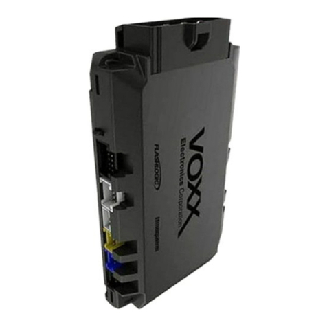
2 Pin Blue Connector : VALET SWITCH
Routethegreyandblack wiresin the2 pinconnectorfromthevalet switchto thecontrolmodule,andplug
it into the mating blue connector on the side of the module.
2 Pin White Connector : DASH MOUNTED LED
Route the red and blue wires in the 2 pin white connector from the LED to the control module, and plug it
into the mating white connector on the side of the module.
4 Pin White Connector : SHOCK SENSOR
Route the red, black, blue, and green wires in the 4 pin white connector from the shock sensor to the
control module, and plug one end into the shock sensor, and the other end into the mating white
connector onthe side of the module.
Red & Green 2 Pin White Connector : DOOR LOCK OUTPUTS
Thesewireswill provide eithera pulsed groundoutputto the factorydoor lock controlrelay,or a pulsed+
12 volt output to the factory door lock control relay. In either case, the maximum current draw through
these outputs must not exceed 300 mA.
3 Wire Ground Switched Door Locks
Inthis application,the red wire providesagroundpulseduringarming,orthepulsed ground lock output.
Connectthe redwiretothewire thatprovides alow currentground signalfrom thefactorydoorlockswitch
to the factory door lock control relay.
Thegreenwireprovidesagroundpulseduringdisarming,orthepulsed ground unlockoutput. Connectthe
greenwireto thewirethat providesalow current groundsignal from thefactory door unlockswitch to the
factory door lock control relay.
