Presto Lifts Power Stak PPS3000-125FS Setup guide

Power Stak
PPS3000-125FS
Installation, Operation
and Service Manual
Model Number _____________________________________
Serial # ____________________________________________
Date Placed in Service _____________
IMPORTANT: READ CAREFULLY
BEFORE INSTALLING OR OPERATING LIFT
Part orders are subject to a $50 minimum charge.
MAR 2014

PRESTO OWNER’S MANUAL Page 2 POWER STAK PPS3000-125FS
This manual was current at the time of printing. To obtain the latest, most updated version, please
contact the Customer Service Department or go to our website: www.PrestoLifts.com -- you will
nd a complete list of current Owner’s Manuals to print.
Presto Lifts Limited Power Stacker Warranty Policy
Presto Lifts warrants the Power Stacker against defects on the mast, fork carriage, chains, pumps,
DC motors, controllers, cylinders and wiring harnesses from faulty material and workmanship for a
period of one (1) year from the date of invoice.
All wear items such as batteries, wheels, motor brushes, seals, bearings, hydraulic hoses, all switches,
battery chargers and forks have a limited warranty against defects in faulty material and workmanship
for a ninety (90) day period from the date of invoice and 30 day limited warranty on labor. Please
note that prior authorization from Presto Lifts is required on all warranty work.
There are no implied warranties of any kind, more specically; there are no warranties of merchant-
ability or tness for any particular purpose. Presto Lifts’ sole warranty shall be as set forth in this
limited warranty. Presto Lifts will elect to repair or replace a defective component without charge,
if any components should become defective within the limited warranty period. Proof of purchase is
required for warranty. The charge for shipping the defective component is the responsibility of the
buyer and must be accompanied with an RGA number. The shipping charge to return the component
to the buyer is the responsibility of Presto Lifts, Inc.
This limited warranty does not cover labor expense for removal or reinstallation of components
after thirty days. This limited warranty shall not cover, among other things: damages resulting
from foreign matter or water, failure to provide reasonable and necessary maintenance, and if
applicable, use of product while charger is plugged into an AC outlet, or failure to follow operat-
ing instructions. The limited warranty is not valid for damage resulting from negligence, accident,
unreasonable use, abuse or misuse, exceeding data plate capacities or altering the product without
Presto Lifts authorization.
Presto Lifts expressly disclaims and excludes any liability for consequential, incidental, indirect
or punitive damages or nancial loss to people or property resulting from any breach of warranty or
the operation or failure of this product.
Presto Lifts makes no representation that this product complies with local, state, or federal safety/
product standards codes. Should this product fail to comply in any way with those codes, it shall
not be considered a defect of materials or workmanship. Presto Lifts shall not be held liable for any
damages resulting from noncompliance. It is the dealer’s responsibility to exercise this limited war-
ranty. This limited warranty is provided to the original purchaser (dened as the original end user)
and is nontransferable. This constitutes the complete and nal agreement involving Presto Lifts and
limited warranty obligations for products.

PRESTO OWNER’S MANUAL Page 3 POWER STAK PPS3000-125FS
TABLE OF CONTENTS
S E C T I O N 1:
Limited Warranty ................................................2
Introduction..........................................................4
S E C T I O N 2:
Safety ................................................................4-5
S E C T I O N 3:
Installation.........................................................5-6
A. Inspection .....................................................5
B. Removing from Pallet ...................................5
C. Preparation for Use.....................................5-6
S E C T I O N 4:
Operation...........................................................6-7
A. Operating Instructions.................................6-7
B. Daily Operations Maintenance Checks ..........7
Suggested Daily Operator Checklist....................8
S E C T I O N 5:
Battery Maintenance ............................................9
A. Preparing to Charge a Battery .......................9
B Charging the battery.......................................9
C. Warnings and Battery Info .............................9
D. Battery maintenance.......................................9
E. Charger Operation ..........................................9
S E C T I O N 6:
Maintenance....................................................9-10
A. Weekly Operations Maintenance Checks.....10
B. Monthly Operations Maintenance Checks ..10
S E C T I O N 7:
Troubleshooting .................................................10
ORDERING REPLACEMENT PARTS ............27
RESTOCKING POLICY...................................27
RETURN GOODS AUTHORIZATION............28
LIST OF FIGURES:
Fig. 1: Operational Buttons.............................................. 6
Fig. 2: Straddle Leg 4 Bolt Tightening ............................. 7
Fig. 3: PPS3000-125FS..................................................11
Fig. 4: PPS3000-125FS Exploded View........................ 12
Fig. 5: PPS3000-125FS Mast Assembly ....................... 13
Fig. 6: PPS3000-125FS Cabinet Assembly................... 14
Fig. 7: PPS3000-125FS Carriage Assembly ................. 15
Fig. 8: PPS3000-125FS Leg Assembly ......................... 16
Fig. 9: PPS3000-125FS Caster Wheel Assembly ......... 17
Fig. 10: PPS3000-125FS Steering Assembly................ 18
Fig. 11: PPS3000-125FS Handle Assembly .................. 19
Fig. 12: PPS3000-125FS Drive Wheel Assembly.......... 20
Fig. 13: PPS3000-125FS Cylinder Assembly................ 21
Fig. 14: PPS3000-125FS Power Unit Assembly............ 22
Fig. 15: PPS3000-125FS Hydraulic Schematic............. 23
Fig. 16: PPS3000-125FS Labels and Warnings............ 24
Fig. 17: PPS3000-125FS Wiring (Aug. 2011 to present) ...... 25
Fig. 18: PPS3000-125FS Battery Connection............... 26

PRESTO OWNER’S MANUAL Page 4 POWER STAK PPS3000-125FS
S E C T I O N 1
INTRODUCTION
This manual attempts to provide all of the information nec-
essary for the safe and proper installation, operation and
maintenance of Presto Lifts Inc. battery operated, Power
Stak. It is important that all personnel involved with the
installation, maintenance or operator of the stacker read this
manual. Additional manuals are available upon request or
at www.PrestoLifts.com.
Each Presto stacker is equipped with nameplate, serial num-
ber and model identications. Please refer to these numbers
when ordering parts or requesting further information.
The Presto stackers are designed for lifting, lowering and
positioning a wide variety of loads. WHERE UNIQUE
SITUATIONS ARISE, WHICH ARE NOT COVERED IN
THIS MANUAL, CALL PRESTO LIFTS FOR FURTHER
INSTRUCTIONS.
The battery operated stackers are designed for in-plant/non-
hazardous locations only. They can be used in a 8’ or larger
aisle. These units are not for personnel lifting.
S E C T I O N 2
SAFETY
You must be trained and certied to operate this
powered stacker. Federal law states that only prop-
erly trained operators are permitted to operate a
powered industrial stacker and that your employer
must train you and certify that you are qualied.
(OSHA 1910.178 29QFR-7-1-06 Edition)
Presto lifts does not offer operator training. Op-
erator training programs may be offered by your
local Presto Lifts dealer or obtained online. Enter,
“powered industrial truck operator training” into
a search engine.
The battery operated stackers are very powerful lifts capable
of doing large amounts of work.
DO NOT OPERATE THESE LIFTS WITHOUT CARE-
FULLY READING THIS MANUAL. In order to provide
for the safe operation of these stackers, Presto Lifts Inc. has
identied certain hazards that may occur during the mainte-
nance and use of these lifts. For safety reasons these units
are designed to be serviced or repaired in the fully lowered
position. If performed properly, this will greatly reduce the
possibility of injury.
WARNING!
When servicing the unit:
1. Key should be in “OFF” position.
2. E-stop should be depressed.
3. Disconnect the batteries at the terminals.
•Do not perform any repair work on lifts if there is a
load on the forks or platform.
•Do not perform any repair work if the forks or platform
is in the raised position.
•All personnel must stand clear of the lift while in mo-
tion.
•Do not put hands or feet under the forks or platform.
•Do not stand underneath the forks or platform.
•Do not stand in front of the stacker while in motion.
•Do not stand, sit or climb on the lift.
•Do not use the lift on soft, uneven or unstable surfaces.
•Do not exceed the load center or capacity.
WARNING!
You or others around you can be seriously injured or even
killed if you don’t use this stacker correctly. Read and
obey all warnings and instructions in this manual and on
the stacker. It is your responsibility before starting work
to make sure it is in good working order.
Always be alert to the area around you and watch where
you are walking. Be careful that you don’t get pinned or
crushed between the stacker and a xed object such as a
wall or post.

PRESTO OWNER’S MANUAL Page 5 POWER STAK PPS3000-125FS
•Watch your hands and feet. A foot or hand caught
between the stacker and a xed object will be crushed
or even cut off.
•If traveling forks rst, keep both hands on the control
handle and be careful when changing direction of
travel. Keep your feet clear of the stacker.
•Keep the stacker under control at all times. Operate at
a speed that allows you to stop safely. Be even more
careful on slippery or uneven surfaces. Do not run over
objects on the oor.
•Perform all stacker movements smoothly and at a
speed that will give you time to react if an emergency
occurs.
Tipovers and falls are very serious accidents; you can be
crushed or even killed. To prevent injury, know where you
are at all times and follow the rules of safe stacker operation.
•Be careful when working around docks, dockboards
and trailers. Stay away from the edge of docks and
ramps. Check to make sure the wheels of truck or trail-
ers are chocked.
•Travel with the load or forks close to the ground.
Watch for overhead obstructions. Perform all stacker
movements smoothly and at a speed that will give you
time to react in an emergency.
•Keep your hands and feet away from all moving parts
such as masts, chains, forks or wheels.
•Never stand on or under the forks, or allow anyone
else to stand on or under them. Never ride on the
stacker or allow anyone else to ride. There is no safe
place to sit or stand.
•Before you leave your stacker, be sure to lower the
forks to the oor. Shut the stacker off with the key.
WARNINGS
DO NOT use this stacker until you have been trained and
authorized to do so.
DO NOT operate until you have read all warnings and in-
structions.
DO NOT exceed load center or load weight capacities (check
capacity plate).
DO NOT operate until you have checked the conditions of
the stacker: lift systems, forks, chains, and cables.
DO NOT use if any part is damaged, worn or not working
properly.
DO NOT use on ramps or inclines. Only smooth level sur-
faces.
DO NOT use for lifting or carrying people.
DO NOT handle unbalanced, unstable or loosely stacked
loads.
DO NOT travel with forks or platform in an elevated posi-
tion.
DO NOT handle tall, unsecured or unstable loads that could
fall.
DO NOT allow people to stand or pass under forks or plat-
form with or without load.
DO NOT operate when parts of anyone’s body may be close
to mast structure or any moving parts.
DO NOT drop loads on platform or forks.
DO NOT alter or modify this stacker in any way.
S E C T I O N 3
INSTALLATION
A. INSPECTION:
Upon receipt of the stacker, inspect the equipment completely
to determine if there is any shipping damage, and that the lift
is complete. Presto tests and inspects every piece of equip-
ment prior to shipment. If damage is apparent, a freight
claim must be led with the freight company. Do not use the
stacker if there appears to be any damage. With the stacker
in a lowered position, check the following:
•Check for signs of damage especially to the back
cabinet that houses the battery, electrical/hydraulic
power pack.
•Check all electrical and hydraulic connections for
tightness.
•Remove back panel.
1. Turn key switch to “OFF” position.
2. Push in E-stop and unscrew the red knob,
3. Lift off back panel. There is enough wire to the
key switch to allow the panel to be set aside.
•Inspect for any bent or damaged parts.
B. REMOVING FROM PALLET
Each of the Presto stackers is shipped out on a pallet or skid.
Prior to removing the unit from the pallet or skid, remove
all tie down straps and packaging. Visually inspect the unit
as closely as possible.
With an overhead hoist or forklift, carefully pick up the unit
taking into consideration the center of gravity of the unit.
If you choose to pick the unit with an overhead hoist, use a
nylon sling and hoist with a minimum of 2,000-lb. capacity.
The nylon sling will not do any damage to the steel construc-
tion of stacker. Pick the unit up. On conventional masts use
the top cross member of the lift. On narrow masts the cover
must be removed to access lifting equipment. Be careful of
the stacker swinging once fully lifted off the pallet or skid.
Have all personnel completely cleared from the area.
Pick the unit up approximately six inches above the pallet
or skid. Once raised, remove the pallet or skid from below
the lift. Do not move the lift around in the air. Lower the
stacker on the ground.
C. PREPARATION FOR USE
This stacker left our factory in new condition. It has been
inspected and weight tested to assure all performance stan-
dards have been met.
Visually inspect the stacker for damage. Check for attach-
ments and accessories that may have been ordered. If there
is any damage or missing parts, report it to your carrier and
your Presto dealer immediately.
Remove all metal/plastic bands, cardboard and other material
PRESTO OWNER’S MANUAL Page 6 POWER STAK PPS3000-125FS
used for shipping purposes.
Check to see if chains are in place, and that the lift system is
in working order. Inspect for oil leaks.
See instructions for removing back panel on pg. 5.
Connect battery cable. Check cables and wires on battery
charger as well as battery.
S E C T I O N 4
OPERATION
A. OPERATING INSTRUCTIONS:
To Raise and Lower:
There are two buttons located on both sides of the handle.
The inside one is for raising the forks. The outside one is for
lowering the forks. When operating, always make sure the
load being lifted is within the loading capacity of your stacker
and the load has been stacked safely on the pallet. Also, make
sure that the length of the forks corresponds to the length of
the pallet. In this way, the load rollers will place themselves
in the opening at the end of the pallet, so that when you
raise the forks, you will not break the bottom boards of the
pallet. Always make sure that when entering the pallet that
the forks are in the fully lowered position. Be careful when
lifting pallets that are too short or too long for the stacker.
It might destroy your pallet by breaking the bottom boards,
and if the forks project through the end of the pallet, the tips
of fork may go into the next pallet that is behind the pallet
that you are lifting, which may bend the tips of forks and
overload the capacity of the stacker.
To Travel:
To travel, rotate the buttery controls throttle on the upper
part of the handle. When rotating the buttery control CW
towards the forks, the stacker runs forwards in the forks rst
direction. When rotating the buttery CCW towards you, the
stacker runs backwards in the handle rst direction. Always
make sure the stacker clears any obstruction when travel-
ing, and that your path of travel is clear of people. Never
carry loads above the loading capacity of the stacker. It is
suggested that when traveling without a load, the forks be in
the lowered position. The speed of the stacker is increased
by the degree of the rotation in either direction; it functions
like a throttle. When you release your hand from the buttery
control, it automatically will resume to the neutral position
and the speed of the stacker will slow down.
To Brake:
Your stacker is equipped with a magnetic brake. The brake
is applied when the handle is in its vertical position between
10 – 15 degrees and lowered position between 80 – 90 de-
grees. The brake could be released when you pull down the
handle at any point between 15 – 80 degrees. Always make
sure the brake is released before operating the stacker. When
the stacker is running, you could brake the stacker by raising
the handle to its vertical position or lowering the handle to
its lowest position. Or, to turn the buttery controls in the
opposite direction, the change in direction of the motor will
slow down, stop, and reverse the direction of stacker. When
parked, always put the handle in the full vertical position
with the brake applied and the forks in lowered position.
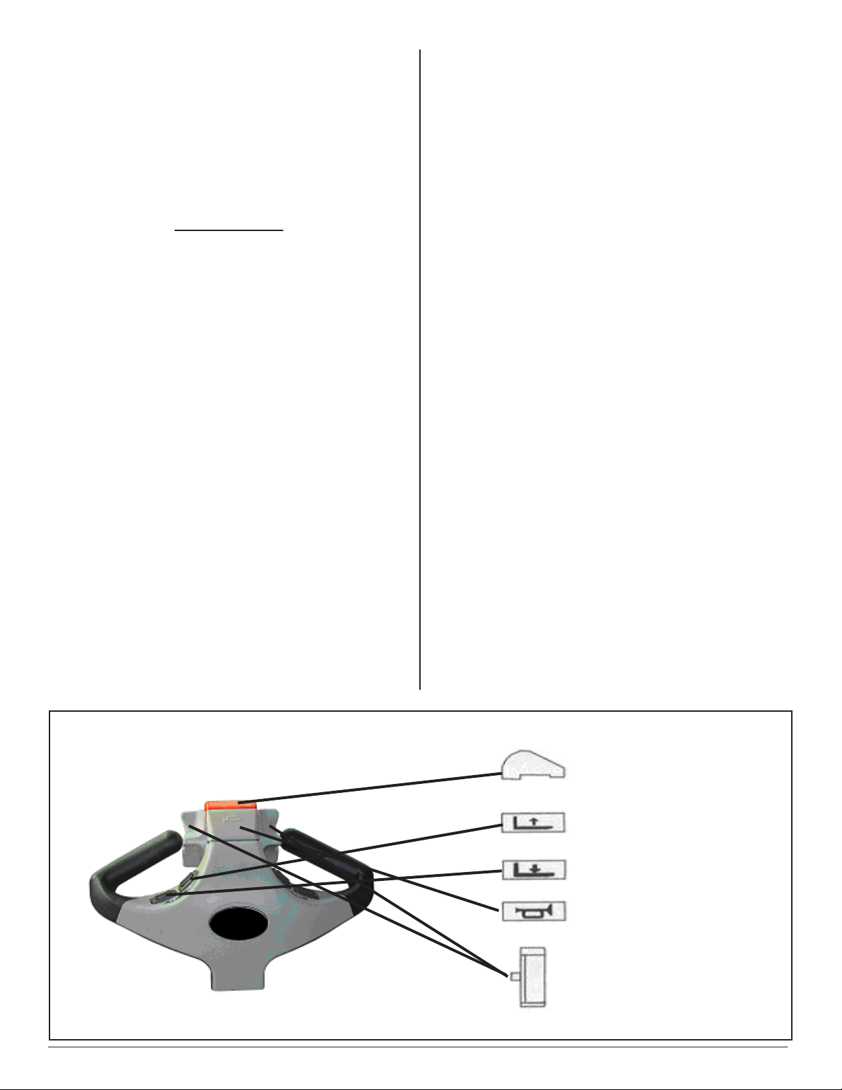
Figure 1: Operational buttons
BELLY BUTTON SWITCH
LIFT UP
LIFT DOWN
HORN
SPEED CONTROL
DIRECTION CONTROL
PRESTO OWNER’S MANUAL Page 7 POWER STAK PPS3000-125FS
Reversing Safety:
At the end of the handle there is a large, red reversing bar
(belly button switch) that is designed to protect the operator
from injury. When the operator runs the stacker backwards,
and the end of the handle comes in contact with the operator’s
body, the stacker will automatically reverse direction and
travel away from the operator. When the reversing safety
bar comes in contact with your body during operation,
immediately release your hands from the buttery control
and put the handle up to its vertical position or down to its
lowest position and the brake is on. The reversing safety bar
will automatically resume to its original position after being
activated.
Horn:
As standard equipment, a horn that is located on the top of
the handle.
AUTHORIZED OPERATORS SHOULD READ
AND UNDERSTAND ALL INSTRUCTIONS,
PRECAUTIONS AND WARNINGS.
IMPROPER USE OF THIS LIFT TRUCK COULD
RESULT IN INJURY AND/OR DAMAGE
TO LOAD AND EQUIPMENT.
•Inspect the lift for damaged or worn parts. Do not use
if not in safe operating condition.
•Use lift on hard level surfaces only.
•Make sure load is evenly distributed, not loose or un-
stable, and is as far back on platform or forks as possible.
Do not pick up loads on tips or forks or edge of platform.
•Do not overload. Check load center and load weight
capacities on the nameplate.
•Make sure travel and work area is clear of obstruc-
tions.
•Check overhead clearance before lifting loads or trans-
porting.
B. DAILY OPERATIONS
MAINTENANCE CHECKS:
1. Battery
A. Check for corroded and loose terminals. A white
powder substance will be present if there is any
existing corrosion.
B. Visually inspect for any cracks or damage to the
casing.
C. Check for loose battery tie-downs.
2. Charger
A. Inspect wire connections.
B. Check power cord for nicks/damage.
C. Check power charger for proper mounting.
3. Hydraulic System
D. Inspect pump and cylinder for oil leaks.
E. Check hydraulic oil level.
F. Check hydraulic ttings and hoses.
G. Check ram for nicks/damage.
4. Frame Assembly
A. Check chain roller assembly connections.
B. Check for any worn or damaged parts.
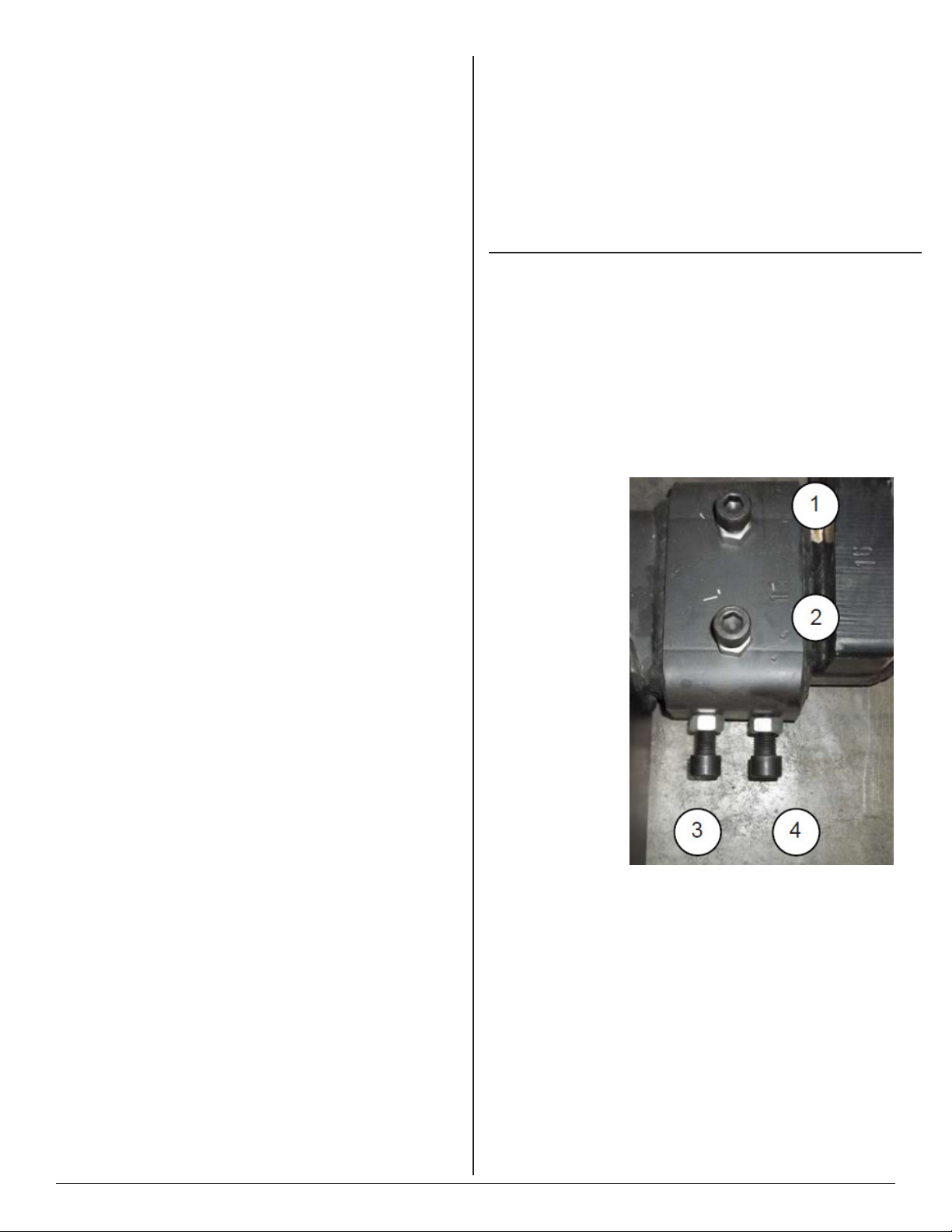
Straddle Leg Bolt Tightening Procedure
1. Pre-tighten all bolts to the bottom, but not too tight.
2. Fully tighten bolt 1.
3. Next, tighten bolt 3.
4. Next, tighten bolt 4.
5. Last, tighten bolt 2.
6. Tighten all bolts to 85 foot pounds.
Set up procedure
for PowerStak
Straddle legs with
4 Bolts
Figure 2:
Note: The Power Stak is meant to operate on a non slip
oor or surface. If traction is needed, Presto Lifts offers
an optional rubber wheel or a non-marking wheel.
Set up procedure for PowerStak
Fixed Removable straddle legs
1. Install both legs into the leg cup holders evenly on both sides
of the lift. Check to insure the ID of the legs does not exceed 50”
and each leg should be inserted into the holder evenly.
2. Relieve any weight from the legs. This may need to be done
one side at a time.
3. Adjust the legs and ensure both legs are positioned equally.
Please refer to diagram below.

PRESTO OWNER’S MANUAL Page 8 POWER STAK PPS3000-125FS
DAILY OPERATOR CHECK LIST
CHARGE CONDITION/BATTERY CHECK LIST
1. Check Battery Discharge Indicator (Fuel Gage and Hour Meter) – Be sure unit is
showing proper Charge Level before operating unit
2. Check to be sure Charging Cord is Unplugged and properly stowed before operat-
ing unit
3. Inspect Battery Wire Connections – All connections should be tight with No Corro-
sion (white powder) showing at the Battery Terminals
4. Inspect Battery Case – There should be no cracks or visible damage to the Battery
Case
WALK AROUND INSPECTION
1. Check general condition of Stacker (loose or broken parts, oil, dangling wires, dents,
cracked covers etc.)
2. Check metal frame, mast, carriage and font load supports for cracked welds, worn or
at rollers, loose or disconnected chains, loose pins, missing snap rings, and loose or
missing hardware – bolts, nuts washers etc.
3. Check for evidence of hydraulic leaks
4. Make sure all precautionary labeling is in place and legible
FUNCTIONAL INSPECTION
1. Check Drive – Forward and Reverse Function
2. Check Lift – Up and Down Function
3. Check Function for Belly Button Reverse
4. Check Horn Function
5. Check Brake Function
OPERATOR ID DATE
DO NOT USE OR OPERATE STACKER IF ANY FUNCTION IS NOT
OPERATING PROPERLY OR IF STACKER APPEARS UNSAFE IN ANYWAY
REPORT CONCERNS TO SUPERVISOR IMMEDIATELY!

PRESTO OWNER’S MANUAL Page 9 POWER STAK PPS3000-125FS
S E C T I O N 5
BATTERY MAINTENANCE
A. PREPARING TO CHARGE A BATTERY
1. Always turn off E-stop and key switch before working
with the batteries.
2. Be sure the area around the stacker and the battery is
well ventilated while battery is being charged.
3. The battery terminals, connections and wiring connec-
tions should be clean and free of corrosion. When clean-
ing any of these components wear a face shield or other
suitable protective eyewear.
B. BATTERY CHARGING
Charging must be performed with the charger that is provided
with or prewired into the machine. During charging, the
temperature in the battery must not exceed 120 F. Charging
simultaneously with truck operation is not recommended.
Plug the charger into a 115 volt outlet. Charge until the bat-
tery gauge indicator lights show fully charged (approximately
6-8 hours).
C. WARNINGS AND BATTERY INFORMATION
Avoid use of open ame near batteries. At temperatures
around freezing point, battery capacity is reduced by 30%.
The battery terminals, connections and wiring should be
clean and free of corrosion. When cleaning any of these
components, wear a face shield or other suitable protective
eyewear. Read, understand, and follow all battery and battery
manufacturer’s specic precautions while working with and/
or charging batteries.
D. BATTERY MAINTENANCE
To measure the voltage, use a digital voltmeter (DC) on the
battery poles. The truck must not have been in use for the
previous 30 minutes.
DANGER
Never alter the AC cord or plug provided. If it will not
t outlet, have proper outlet installed by a qualied elec-
trician. Improper connection can result in a risk of an
electric shock.
1. Disconnect the charger from the 115 volt wall outlet
once the indicators read fully charged.
Note: The batteries are designed for intermittent use.
Continual usage will wear the battery out and charging
will be required.
E. CHARGER OPERATION
Power Lamp
1. Green: Connection correct. Charger will operate nor-
mally.
2. Red: Bad connection or bad battery.
Fault
1. Red light blinks 3 times in 5 seconds: The output between
charger is faulty, loose, or bad connection
2. Red light blinks 5 times in 5 seconds: The temperature
is too hot for the charger to operate.
3. Building power is not compatible; too low or too high.
+- 10% is the general rule.
Charge Lamp
1. Red: Charger can charge normally. The battery is less
than 70%
2. Orange: Battery is between 70% and 100% charged.
3. Green: Battery is at 100%. Fully charged.
4. No light: The charger can not charge the battery. Voltage
of the battery may be too low to cause the charger to start. It
must be at 10.5 volts to initiate charge.
S E C T I O N 6
MAINTENANCE
Operation of Presto Power Stak is very simple — as is their
construction. They require very little maintenance. Reason-
able care will result in excellent trouble-free performance.
The Power Stak is designed for one-man operation and ease
of performance.
•Grease oor wheels and casters at least once a month.
•Use only Hydraulic Oil AW32 or Dextron III in the
hydraulic system.
•Do not overload your lift.
•Check brakes, steering mechanisms and controls be-
fore each use.
VOLTAGE
Approx. 12.7 V..... Fully charged
Approx. 12.2 V........ 1/2 charged
Approx. 12.0 V........ 1/4 charged
Approx. 11.6 V........ Discharged

PRESTO OWNER’S MANUAL Page 10 POWER STAK PPS3000-125FS
A. WEEKLY OPERATIONS
MAINTENANCE CHECKS:
1. DAMAGE: Check for bent, dented, worn or broken
parts.
2. LIFT SYSTEM: Check to assure that there is no bind-
ing or excessive play in the forks. Check for quiet and
smooth operation of the lift cylinder. Check all moving
parts and linkage.
3. LEAKS: Check hydraulic system for leaks and hydraulic
oil level.
4. WHEELS AND CASTERS: Check for wear and that
they are turning smoothly.
5. LIFT CHAINS: Check to see that they are in place and
not loose.
6. FORKS: Check that they are not bent or cracked.
7. BRAKES: Ensure brakes work properly.
8. CABLES; WIRES: Check that there are no loose cables
or wires.
9. LABELS: Ensure all precautionary labels and guards
are in place.
B. MONTHLY OPERATIONS
MAINTENANCE CHECKS:
1. Battery (maintenance free)
A. Clean terminals.
B. Clean battery compartment area if there are signs
of corrosion.
2. Hydraulic System
A. Clean and inspect hydraulic cylinder.
B. Lubricate chain with a rust inhibitive lubricant
(light machine oil).
C. Check chain tension. It should be even on both
chains. The chain should be tight enough so that
it does not come off of the roller assembly.
3. Frame Assembly
A. Clean and lubricate all roller bearings, cam fol-
lowers and all moving parts.
B. Clean and inspect all welds.
C. Check wheels for wear and damage.
D. Inspect nameplate for legibility. Place the serial
and model number shown on the nameplate on the
cover of the manual for future reference.
4. Electrical
A. Check batteries, motors, controllers, limit switches,
electrical conductors and connections.
CAUTION:
DO NOT USE LIFT IF IT IS NOT OPERATING
PROPERLY, OR APPEARS UNSAFE IN ANY WAY!
S E C T I O N 7
TROUBLESHOOTING
Before starting the troubleshooting, you have to:
A. Put the truck on an even and solid surface.
B. Turn off key switch or disconnect the battery termi-
nals.
1. Unit will not lift (motor does not run)
• Faulty wiring from fuse to lift switch in handle
• Faulty lift switch
• Faulty wiring from battery positive terminal to pump
contactor to pump motor
• Burned out brushes in pump motor
• Low hydraulic pressure caused by:
¨ Pressure relief valve needs adjustment
¨ Pump check valve stuck open
¨ Faulty solenoid valve
• Faulty wiring from lift switch to solenoid
• Faulty lift contactor
• Defective control circuit fuse
• Chain or roller bound
• Check oil level
2. Forks will not lower
• Look for binding in chains or rollers
3. No electrical power
Dead Batteries:
¨ Key switch on “OFF” position
¨ E-stop button depressed
¨ Loose or dirty battery connections
¨ Blown fuse(s)
• Faulty wiring from fuse to travel control switch
• Faulty control switch
• Faulty wiring from travel control switch direction con-
tactor
• Faulty contactor
4. No Traction
•Check to insure base legs are torqued properly.
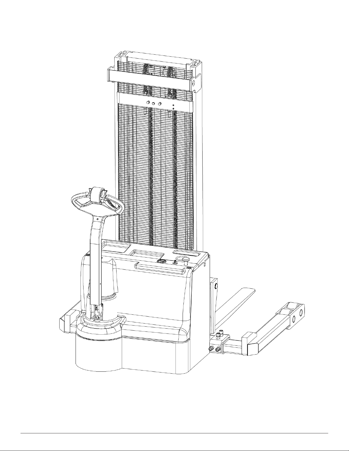
PRESTO OWNER’S MANUAL Page 11 POWER STAK PPS3000-125FS
PPS3000-125FS
Figure 3:

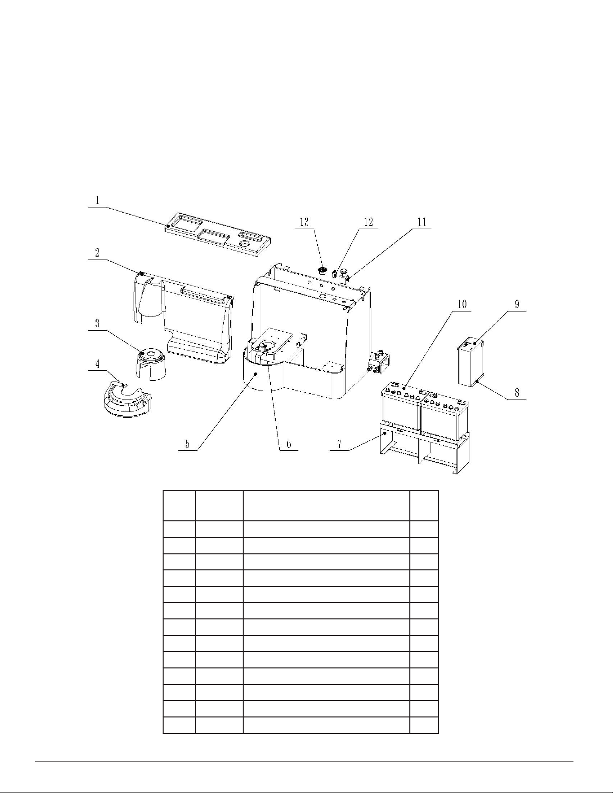
PRESTO OWNER’S MANUAL Page 12 POWER STAK PPS3000-125FS
PPS3000-125FS Exploded View
Item Parts No. Description Qty
1 1000 Body weld 1
2 2000 Mast assembly 1
3 3000 Lift mechanism 1
4 4000 Fork assembly 1
5 5000 Balance wheel 1
6 7000 Gear assembly 1
7 8000 Electric system 1
8 9000 Power unit 1
Figure 4:
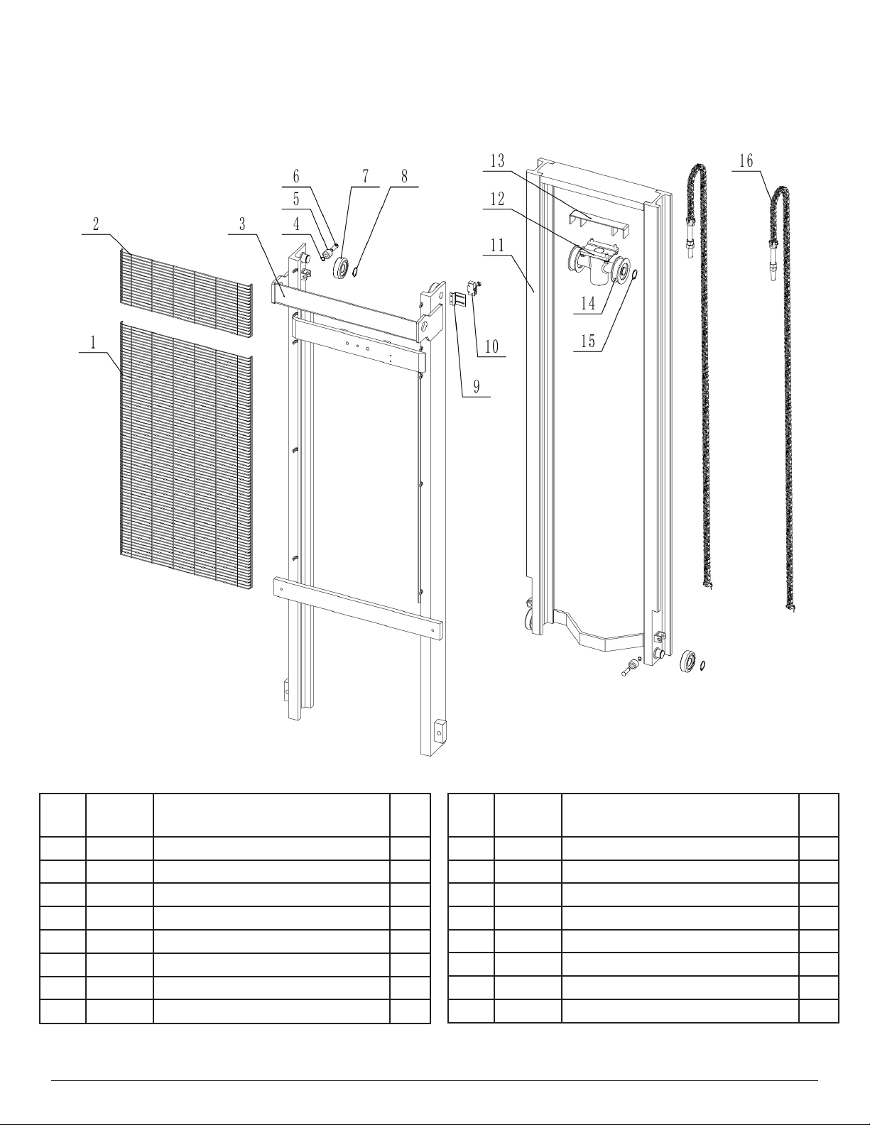
PRESTO OWNER’S MANUAL Page 13 POWER STAK PPS3000-125FS
PPS3000-125FS Mast Assembly
Item Parts
No.
Description Qty
1 2101 Top safety net 1
2 2102 Middle safety net 1
3 2200 Mast weldment Outer 1
4 2201 Snap ring Ø12 MM 4
5 2202 Guide roller 4
6 2203 Guide roller shaft 4
7 2204 Roller bearing 30706V 4
8 2205 Snap ring Ø30 MM 1
Item Parts
No.
Description Qty
9 2103 Limit switch holder 1
10 2104 Limit switch TM1703 1
11 2300 Inner mast 1
12 1505 Chain wheel frame 1
13 1504 Chain wheel protective assembly 1
14 1503 Chain wheel bearing 78060V 1
15 1502 Snap ring Ø30 MM 2
16 1501 Chain LH1223 2
Figure 5:
PRESTO OWNER’S MANUAL Page 14 POWER STAK PPS3000-125FS
PPS3000-125FS Cabinet Assembly
Item Parts
No.
Description Qty
1 1101 Battery box cover 1
2 1102 Rear box cover 1
3 1103 Steering shaft-cap 1
4 1104 Driving wheel cover 1
5 1201 Rear box 1
6 1202 Cover holder 1
7 1203 Battery holder 1
8 1204 Charger holder 1
9 1301 Charger 1
10 1302 Battery 2
11 1303 Main switch 1
12 1304 Key switch 1
13 1305 Battery meter 1
Figure 6:

PRESTO OWNER’S MANUAL Page 15 POWER STAK PPS3000-125FS
Item Parts
No.
Description Qty
1 3100 Lift frame 1
2 3200 Forged fork 2
3 3301 Fork shaft 1
4 3401 Idler wheel block 4
5 3402 Washer 4
6 3403 Snap ring Ø30 MM 4
7 3404 Roller bearing 30706V 4
8 3405 Bolt 4
9 3406 Nut 4
10 3302 Snap ring Ø35 MM 2
PPS3000-125FS Carriage Assembly
Figure 7:

PRESTO OWNER’S MANUAL Page 16 POWER STAK PPS3000-125FS
Item Parts
No.
Description Qty
1 4101 Leg assy 1
2 4102 Front wheel shaft 2
3 4103 Snap ring Ø35 MM 2
4 4201 Washer 4
5 4202 Ball bearing 6307 4
6 4203 Front wheel 2
PPS3000-125FS Leg Assembly
Figure 8:
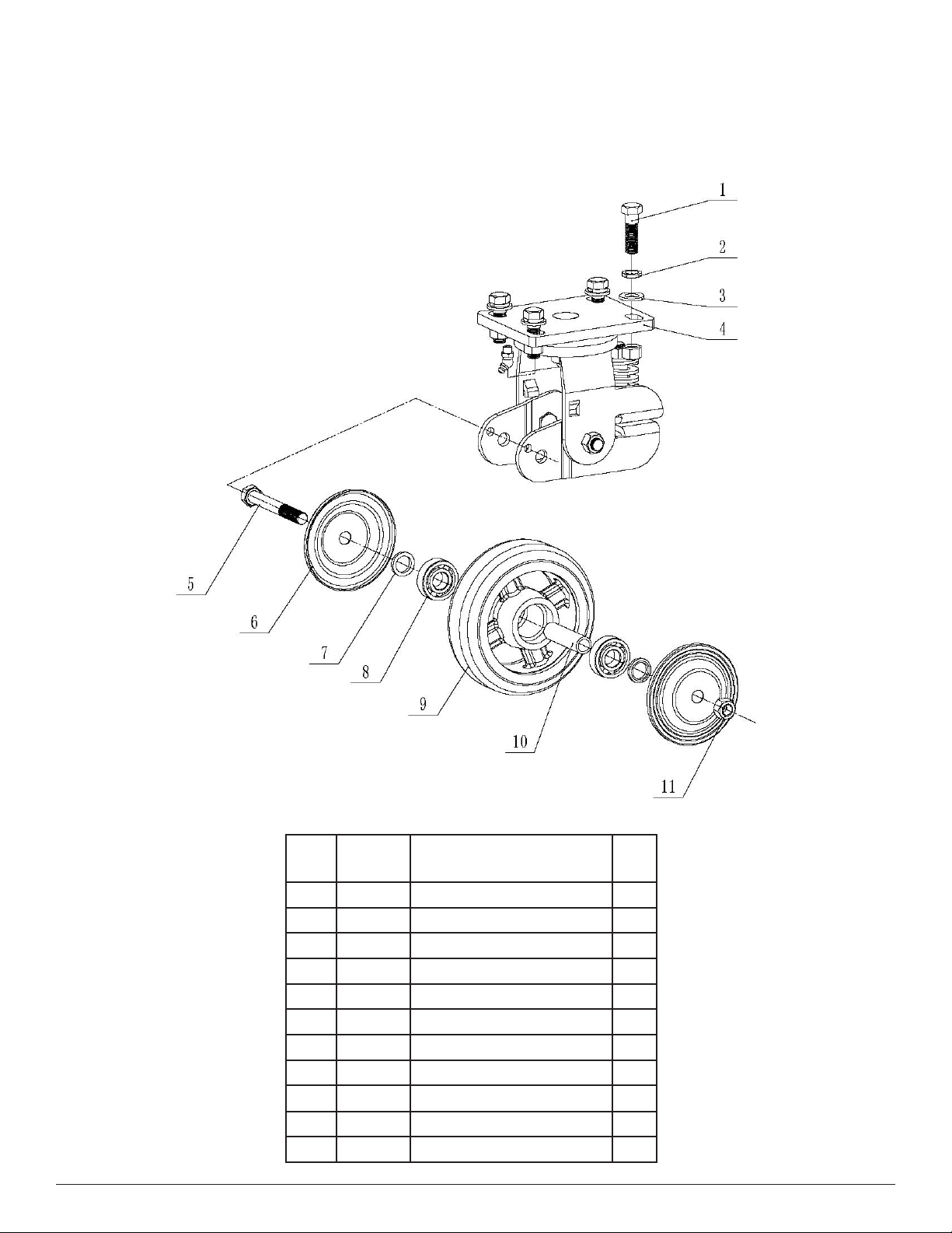
PRESTO OWNER’S MANUAL Page 17 POWER STAK PPS3000-125FS
Item Parts
No.
Description Qty
1 5101 Bolt M12X40 4
2 5102 Spring washer 12 MM 4
3 5103 Flat washer 12 MM 4
4 5104 Rear wheel frame 1
5 5201 Bolt M12X90 1
6 5202 Rear wheel side cover 2
7 5203 Snap ring 2
8 5204 Ball bearing 6203 2
9 5205 Wheel Ø150 MM 1
10 5206 Sleeve 1
11 5207 Nut M12 1
PPS3000-125FS Caster Wheel Assembly
Figure 9:
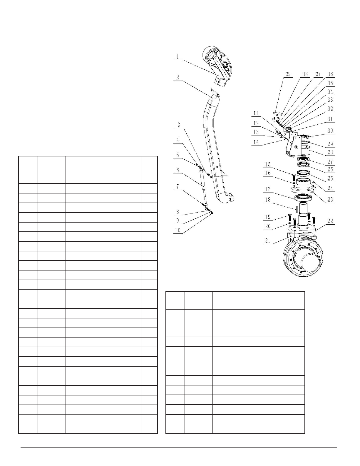
PRESTO OWNER’S MANUAL Page 18 POWER STAK PPS3000-125FS
PPS3000-125FS Steering Assembly
Item Parts
No.
Description Qty
28 7030 Handle base 1
29 7029 Round nut stop washer
Ø52 MM
1
30 7028 Round nut M52X1.5 1
31 7027 Bolt M4X25 2
32 7025 Flat washer Ø4 MM 2
33 7024 Limit switch TM1703 1
34 7023 Nut M4 2
35 7022 Nut M6 2
36 7021 Flat washer Ø6 MM 2
37 7020 Spring washer Ø6 MM 2
38 7019 Bolt M6X25 2
39 7018 Cover holder 1
Item Parts
No.
Description Qty
1 7100 Handle CH-2 1
2 7001 Handle pipe weld 1
3 7004 Pin 1
4 7002 Snap ring Ø8 MM 1
5 7003 Holder 2
6 7005 Air spring 1
7 7006 Bolt 1
8 7007 Flat washer 2
9 7008 Spring washer 1
10 7009 Lock nut 1
11 7026 Short screw 2
12 7010 Washer 2
13 7011 Spring washer 2
14 7012 Bolt M6X12 2
15 7013 Bolt M10X30 4
16 7014 Spring washer 4
17 7015 Bearing 33013 1
18 7036 A-at key 8X45 MM 1
19 7016 Bolt M10X30 4
20 7017 Spring washer Ø10 MM 4
21 7200 Drive wheel (1200W) 1
22 7037 Steering rod weld 1
23 7035 Drive wheel cover 1
24 7034 Grease zerk M8X1 1
25 7033 Ball bearing 61812 1
26 7032 Nut collar 1
27 7031 Round nut M56X2 1
Figure 10:
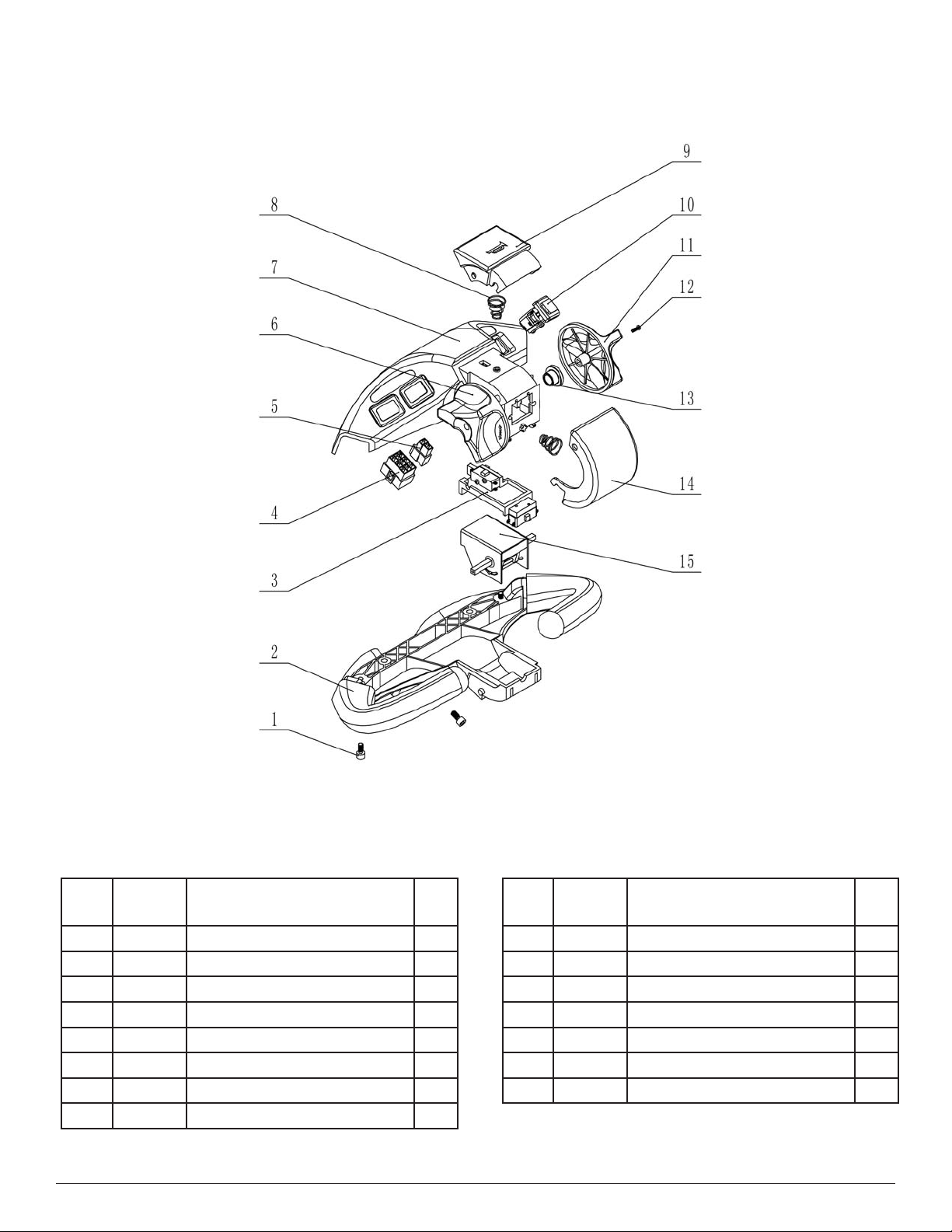
PRESTO OWNER’S MANUAL Page 19 POWER STAK PPS3000-125FS
PPS3000-125FS Handle Assembly
Item Parts
No.
Description Qty
1 7101 Bolt M6-12 3
2 7102 Handle bottom cover 1
3 7103 Front button 1
4 7104 Electrical outlet (big) 1
5 7105 Electrical outlet (small) 1
6 7106 Left handle cover 1
7 7107 Handle top cover 1
8 7108 Spring 2
Item Parts
No.
Description Qty
9 7109 Horn button 1
10 7110 Button group 1
11 7111 Right handle cover 1
12 7112 Screw M3X10 2
13 7113 Washer 2
14 7114 Switch cover F/R 1
15 7115 Forward/backward button 1
Figure 11:

PRESTO OWNER’S MANUAL Page 20 POWER STAK PPS3000-125FS
Item Parts
No.
Description Qty
1 7201 Gear 1
2 7202 Seal 1
3 7203 Gear box 1
4 7204 Spring washer 6 MM 3
5 7205 Screw M6X60 3
6 7206 Gear (2) 1
7 7207 Snap ring Ø15 1
8 7208 Washer 1
9 7209 Ball bearing 6002-2LS/P6 1
10 7210 Ring 1
11 7211 Break S0B-08-2 1
12 7212 Screw M5X50 3
13 7213 Spring washer Ø14 MM 1
14 7214 Gear Axle 1
15 7215 Key 8X7X18 1
PPS3000-125FS Drive Wheel Assembly
Item Parts
No.
Description Qty
16 7216 Ball Bearing 6006 2
17 7217 Gear (2) 1
18 7218 Seal 1
19 7219 Bearing cover 1
20 7220 Screw M5X12 3
21 7221 DC Motor (DC24V 1.2KW) 1
22 7222 Key 5X5X16 MM 1
23 7223 Key 5X5X18 MM 1
24 7224 0 Seal Ø48.7 x Ø2.65 MM 1
25 7225 Washer 1
26 7226 Screw M6X16 10
27 7227 Wheel Ø250X100 MM 1
28 7228 Oil seal Ø140XØ180X12 MM 1
29 7229 Ball bearing 61926 1
30 7230 0 ring 180 MM 1
Figure 12:
Table of contents
Other Presto Lifts Forklift manuals

Presto Lifts
Presto Lifts PPS2200-62NFO-21 Setup guide

Presto Lifts
Presto Lifts Power Stak PPS2200-101AS Setup guide

Presto Lifts
Presto Lifts PPS2200-62NFO-21 User manual

Presto Lifts
Presto Lifts Power Stak PPS2200-62NAS Setup guide

Presto Lifts
Presto Lifts Power Stak PPS2200-62NAS User manual

Presto Lifts
Presto Lifts PPS1100-62-CB User manual

Presto Lifts
Presto Lifts Power Stak PPS3000-125AS Setup guide

Presto Lifts
Presto Lifts Power Stak PPS2200-62NAS Setup guide

Presto Lifts
Presto Lifts Power Stak PPS2200-150AS Setup guide

Presto Lifts
Presto Lifts PowerStak PPS2200-101AS User manual


