Presto Lifts Power Stak PPS3000-125AS Setup guide

Power Stak
PPS3000-125AS
Installation, Operation
and Service Manual
Model Number _____________________________________
Serial # ____________________________________________
Date Placed in Service _____________
IMPORTANT: READ CAREFULLY
BEFORE INSTALLING OR OPERATING LIFT MARCH 2015
This manual covers PowerStak units with frame numbers
starting with GC stamped into the mast and shipped March
2014 and after.

PRESTO OWNER’S MANUAL Page 2 POWER STAK
This manual was current at the time of printing. To obtain the latest, most updated version, please
contact the Customer Service Department or go to our website: www.PrestoLifts.com -- you will
nd a complete list of current Owner’s Manuals to print.
Presto Lifts Limited Power Stacker Warranty Policy
Presto Lifts warrants the Power Stacker against defects on the mast, fork carriage, chains, pumps,
DC motors, controllers, cylinders and wiring harnesses from faulty material and workmanship for a
period of one (1) year from the date of invoice.
All wear items such as batteries, wheels, motor brushes, seals, bearings, hydraulic hoses, all switches,
battery chargers and forks have a limited warranty against defects in faulty material and workmanship
for a ninety (90) day period from the date of invoice and 30 day limited warranty on labor. Please
note that prior authorization from Presto Lifts is required on all warranty work.
There are no implied warranties of any kind, more specically; there are no warranties of merchant-
ability or tness for any particular purpose. Presto Lifts’ sole warranty shall be as set forth in this
limited warranty. Presto Lifts will elect to repair or replace a defective component without charge,
if any components should become defective within the limited warranty period. Proof of purchase is
required for warranty. The charge for shipping the defective component is the responsibility of the
buyer and must be accompanied with an RGA number. The shipping charge to return the component
to the buyer is the responsibility of Presto Lifts, Inc.
This limited warranty does not cover labor expense for removal or reinstallation of components
after thirty days. This limited warranty shall not cover, among other things: damages resulting
from foreign matter or water, failure to provide reasonable and necessary maintenance, and if
applicable, use of product while charger is plugged into an AC outlet, or failure to follow operat-
ing instructions. The limited warranty is not valid for damage resulting from negligence, accident,
unreasonable use, abuse or misuse, exceeding data plate capacities or altering the product without
Presto Lifts authorization.
Presto Lifts expressly disclaims and excludes any liability for consequential, incidental, indirect
or punitive damages or nancial loss to people or property resulting from any breach of warranty or
the operation or failure of this product.
Presto Lifts makes no representation that this product complies with local, state, or federal safety/
product standards codes. Should this product fail to comply in any way with those codes, it shall
not be considered a defect of materials or workmanship. Presto Lifts shall not be held liable for any
damages resulting from noncompliance. It is the dealer’s responsibility to exercise this limited war-
ranty. This limited warranty is provided to the original purchaser (dened as the original end user)
and is nontransferable. This constitutes the complete and nal agreement involving Presto Lifts and
limited warranty obligations for products.

PRESTO OWNER’S MANUAL Page 3 POWER STAK
TABLE OF CONTENTS
S E C T I O N 1:
Limited Warranty ................................................................................................................................................2
Wheel Traction and Straddle Leg Set-Up ...........................................................................................................4
Introduction.........................................................................................................................................................5
Responsibility of Owners and Users...................................................................................................................6
S E C T I O N 2:
Certied Operator Training.................................................................................................................................7
Safety .................................................................................................................................................................7
S E C T I O N 3:
Installation...........................................................................................................................................................9
A. Inspection ....................................................................................................................................................9
B. Removing from Pallet ..................................................................................................................................9
C. Preparation for Use.......................................................................................................................................9
S E C T I O N 4:
Operation.............................................................................................................................................................9
A. Operating Instructions...................................................................................................................................9
B. Daily Operations Maintenance Checks .......................................................................................................11
Suggested Daily Operator Checklist.................................................................................................................12
S E C T I O N 5:
Battery Maintenance .........................................................................................................................................13
A. Preparing to Charge a Battery ....................................................................................................................13
B Charging the battery....................................................................................................................................13
C. Warnings and Battery Info...........................................................................................................................13
D. Battery maintenance....................................................................................................................................13
E. Charger Operations......................................................................................................................................13
S E C T I O N 6:
Maintenance......................................................................................................................................................14
A. Weekly Operations Maintenance Checks....................................................................................................14
B. Monthly Operations Maintenance Checks .................................................................................................14
S E C T I O N 7:
Troubleshooting ................................................................................................................................................15
Troubleshooting Check List........................................................................................................................ 16-21
ORDERING REPLACEMENT PARTS...........................................................................................................................35
RESTOCKING POLICY..................................................................................................................................................36
LIST OF FIGURES:
Figure 1: Operational Buttons....................................................................................................... 10
Stacker Body Components........................................................................................................... 22
Control Pod................................................................................................................................... 23
Suspension Assembly .................................................................................................................. 24
Drive Unit Assembly ..................................................................................................................... 25
Carriage Assembly ....................................................................................................................... 26
Mast Assembly ............................................................................................................................. 27
Lift Cylinder Assembly .................................................................................................................. 28
Hydraulic Power Unit Assembly.................................................................................................... 29
Hydraulic System Assembly ......................................................................................................... 30
Hydraulic schematic ..................................................................................................................... 31
Electrical Diagrams..................................................................................................................32-33
Label Placement........................................................................................................................... 34
PRESTO OWNER’S MANUAL Page 4 POWER STAK
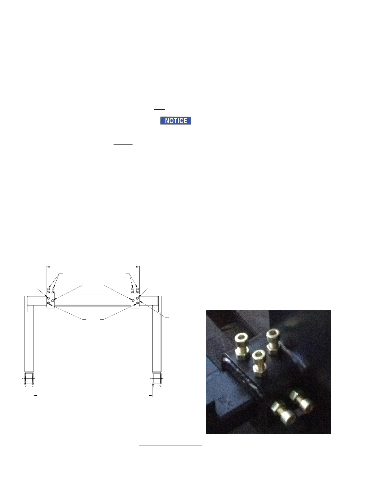
Back off all bolts and follow steps.
First - tighten Bolt 1 to 125 foot pounds
Second - tighten Bolts two (2) to 85 foot pounds
Third - tighten Bolt 3 to 125 foot pounds
Fourth – tighten Bolt 4 to 50 foot pounds - NOT 125 foot pounds!
Last - securely tighten all lock nuts
Set up procedure for PowerStak Straddle legs with 5 Bolts:
Proper Drive Wheel traction is obtained for the PowerStak Straddle unit using this Procedure
All PowerStak Models are designed and intended to operate on an unnished concrete oor surface. If
any PowerStak is operated on smooth or polished concrete, sealed concrete, epoxy sealed oor, linoleum
or other smooth surfaces Drive Wheel traction performance may be affected; If traction issues are encoun-
tered Rubber Drive Wheels are available through special order. Please contact Customer Service at
Presto Lifts 1-800-343-9322
When any PowerStak is operated on a wet, oily, powdery, sandy or non-uniform liquid or granular
surface Drive Wheel traction performance will be affected and loss of traction will occur.
SET-UP PROCEDURE FOR POWERSTAK STRADDLE LEGS
NOTE: STRADDLE LEGS MUST BE ADJUSTED IN ACCORDANCE WITH THIS PROCEDURE
1. PowerStak unit located on at, clean uniform surface, unloaded, forks raised a minimum of 1” off the oor
2. Determine the desired/required straddle width dimension (2 inches greater than pallet width, 1” on each side of
the pallet or load, up to a maximum of 50 inches inside width)
3. Be sure to fully loosen all bolts before moving stabilizing legs. Adjust one stabilizer leg at a time – using a pry
bar, pinch bar, rubber mallet etc. move the straddle leg out from the base tube to the desired position. Do not
move too far, see picture below, if the ¼” wide painted White Line is visible the leg is pulled out too far; Maxi-
mum movement 5 ½” for each leg for 3000 pound units.
4. Adjust second Straddle Leg – using a pry bar, pinch bar, rubber mallet etc. move the straddle leg out from inside
the base tube to the desired straddle width position.
5. Straddle Legs must be symmetrically adjusted, both legs adjusted to the same extended dimension!
CRITICAL – STRADDLE BOLT TIGHTENING SEQUENCE & PROCEDURE
CRITICAL PROCEDURE FOR PROPER WHEEL TRACTION
NOTE:
When adjusted
correctly, white line
cannot be seen.
1270 MAXIMUM
1020 REF.
WHITE LINE
JUST SHOWING
BOLT 4BOLT 4
BOLT 1
BOLT 3
BOLTS 2BOLTS 2

PRESTO OWNER’S MANUAL Page 5 POWER STAK
S E C T I O N 1
INTRODUCTION
This manual attempts to provide all of the information necessary for the safe and proper
installation, operation and maintenance of Presto Lifts Inc. battery operated, Power
Stak. It is important that all personnel involved with the installation, maintenance or
operator of the stacker read this manual. Additional manuals are available upon request
or at www.PrestoLifts.com.
Each Presto stacker is equipped with nameplate, serial number and model identications.
Please refer to these numbers when ordering parts or requesting further information.
The Presto stackers are designed for lifting, lowering and positioning a wide variety of
loads. WHERE UNIQUE SITUATIONS ARISE, WHICH ARE NOT COVERED IN
THIS MANUAL, CALL PRESTO LIFTS FOR FURTHER INSTRUCTIONS.
The battery operated stackers are designed for in-plant/non-hazardous locations only.
They can be used in a 8' or larger aisle. These units are not for personnel lifting.
This machine is designed for powered
travel and should not be manually moved
by applying force to the Control Pod
Handles
The Control Pod and steering arm should
only be moved side to side when the
machine is under power
The Control Pod and steering arm should
be lowered to the drive position and power,
Forward or Reverse, is engaged by moving
the thumb wheel in the direction of desired
travel then the steering arm can be moved
side to side for directional steering.
Pushing or pulling on the Control Pod
Handles when the unit is not powered can
lead to damage and/or breakage

PRESTO OWNER’S MANUAL Page 6 POWER STAK
Responsibility of Owners and Users
Inspection and Maintenance
The device shall be inspected and maintained in proper working order in accordance
with Presto’s owner’s manual.
Removal from Service
Any device not in safe operating condition such as, but not limited to, excessive leakage,
missing rollers, pins, or fasteners, any bent or cracked structural members, cut or frayed
electric, hydraulic, or pneumatic lines, damaged or malfunctioning controls or safety
devices, etc. shall be removed from service until it is repaired to the original manufac-
turer’s standards.
Repairs
All repairs shall be made by qualied personnel in conformance with Presto’s instructions.
Operators
Only trained personnel and authorized personnel shall be permitted to operate PowerStak.
Before Operation
Before using the device, the operator shall have:
• Read and/or had explained, and understood, the manufacturer’s operating instruc-
tions and safety rules.
• Inspected the device for proper operation and condition. Any suspect item shall be
carefully examined and a determination made by a qualied person as to whether it
constitutes a hazard. All items not in conformance with Presto’s specication shall
be corrected before further use of the PowerStak.
During Operation
The device shall only be used in accordance with this owner’s manual.
• Do not overload.
• Ensure that all safety devices are operational and in place.
Modications or Alterations
Modications or alterations to any Presto industrial positioning equipment shall be made
only with written permission from Presto.
Travel speed requirements must be set in the factory prior to shipping. Travel speeds for
this AC Drive System cannot be eld adjusted.
PRESTO OWNER’S MANUAL Page 7 POWER STAK
S E C T I O N 2
CERTIFIED OPERATOR TRAINING
SAFETY ALERT SYMBOLS AND SIGNAL WORDS
The safety of all persons operating, maintaining, repairing, or in the vicinity of this equipment is of paramount
concern. This is a powerful machine with moving parts, and is capable of causing personal injury if proper
precautions are not taken. Therefore, throughout this manual, certain hazards have been identied which may
occur in the use of the machine, and there are appropriate instructions or precautions which should be taken to
avoid these hazards. In some cases, there are consequences which may occur if instructions or precautions are not
followed. Below are the symbols and signal words along with their denitions referenced from ANSI Z535.4 -
Product Safety Signs and Labels.
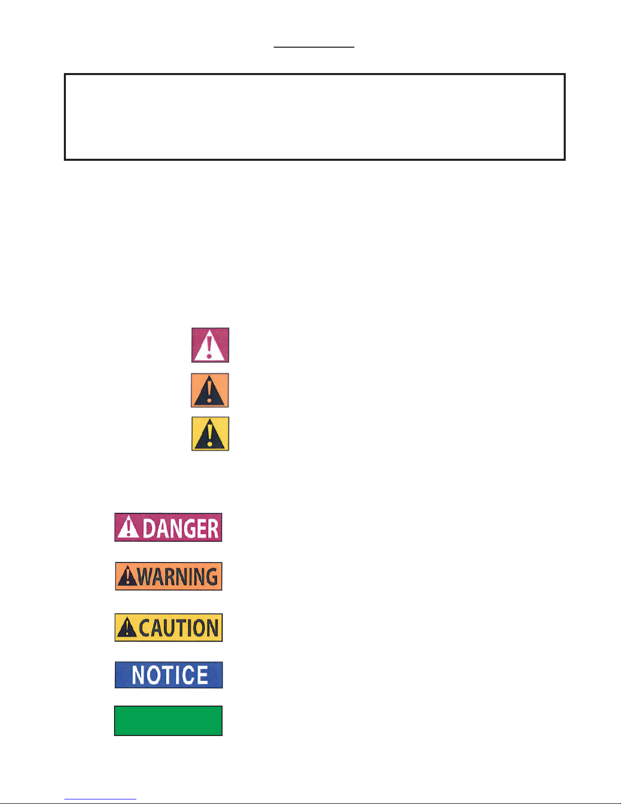
Safety Alert Symbols
These are the safety alert symbols.. They are used to alert you to potential physical injury haz-
ards. Obey all safety messages that follow this symbol to avoid possible injury or death.
For use with DANGER signal word
(Red Background)
For use with WARNING signal word
(Orange Background)
For use with CAUTION signal word
(Yellow Background)
Signal Words
The meaning of different signal words as dened by ANSI Standard Z535.4 indicates the relative
seriousness of the hazardous situation.
DANGER indicates a hazardous situation which, if not avoided,
will result in death or serious injury.
WARNING indicates a hazardous situation which, if not avoided,
could result in death or serious injury.
CAUTION, used with the safety alert symbol, indicates a haz-
ardous situation which, if not avoided, could result in minor or
moderate injury.
NOTICE is used to address practices not related to personal
injury.
(Red Background)
(Orange Background)
(Yellow Background)
(Blue Background)
SAFETY
INSTRUCTIONS
SAFETY INSTRUCTIONS (or equivalent) signs indicate safety-
related instructions or procedures.
(Green Background)
You must be trained and certied to operate this powered stacker. Federal law states that only properly trained
operators are permitted to operate a powered industrial stacker and that your employer must train you and
certify that you are qualied. (OSHA 1910.178 29QFR-7-1-06 Edition)
Presto lifts does not offer operator training. Operator training programs may be offered by your local Presto
Lifts dealer or obtained online. Enter, "powered industrial truck operator training" into a search engine.

PRESTO OWNER’S MANUAL Page 8 POWER STAK
The battery operated stackers are very powerful lifts
capable of doing large amounts of work.
DO NOT OPERATE THESE LIFTS WITHOUT
CAREFULLY READING THIS MANUAL. In order
to provide for the safe operation of these stackers, Presto
Lifts Inc. has identied certain hazards that may oc-
cur during the maintenance and use of these lifts. For
safety reasons these units are designed to be serviced
or repaired in the fully lowered position. If performed
properly, this will greatly reduce the possibility of injury.
WARNING!
When servicing the unit:
1. Key should be in "OFF" position.
2. E-stop should be depressed.
3. Disconnect the batteries at the terminals.
• Do not perform any repair work on lifts if
there is a load on the forks or platform.
• Do not perform any repair work if the forks
or platform is in the raised position.
• All personnel must stand clear of the lift
while in motion.
• Do not put hands or feet under the forks or
platform.
• Do not stand underneath the forks or plat-
form.
• Do not stand in front of the stacker while in
motion.
• Do not stand, sit or climb on the lift.
• Do not use the lift on soft, uneven or unstable
surfaces.
• Do not exceed the load center or capacity.
WARNING!
You or others around you can be seriously injured
or even killed if you don't use this stacker correctly.
Read and obey all warnings and instructions in this
manual and on the stacker. It is your responsibil-
ity before starting work to make sure it is in good
working order.
Always be alert to the area around you and watch where
you are walking. Be careful that you don't get pinned
or crushed between the stacker and a xed object such
as a wall or post.
• Watch your hands and feet. A foot or hand
caught between the stacker and a xed object will
be crushed or even cut off.
• If traveling forks rst, keep both hands on
the control handle and be careful when changing
direction of travel. Keep your feet clear of the
stacker.
• Keep the stacker under control at all times.
Operate at a speed that allows you to stop safely.
Be even more careful on slippery or uneven sur-
faces. Do not run over objects on the oor.
• Perform all stacker movements smoothly and
at a speed that will give you time to react if an
emergency occurs.
Tipovers and falls are very serious accidents; you can
be crushed or even killed. To prevent injury, know
where you are at all times and follow the rules of safe
stacker operation.
• Be careful when working around docks,
dockboards and trailers. Stay away from the
edge of docks and ramps. Check to make sure the
wheels of truck or trailers are chocked.
• Travel with the load or forks close to the
ground. Watch for overhead obstructions. Per-
form all stacker movements smoothly and at a
speed that will give you time to react in an emer-
gency.
• Keep your hands and feet away from all mov-
ing parts such as masts, chains, forks or wheels.
• Never stand on or under the forks, or allow
anyone else to stand on or under them. Never ride
on the stacker or allow anyone else to ride. There
is no safe place to sit or stand.
• Before you leave your stacker, be sure to
lower the forks to the oor. Shut the stacker off
with the key.
WARNINGS
DO NOT use this stacker until you have been trained
and authorized to do so.
DO NOT operate until you have read all warnings and
instructions.
DO NOT exceed load center or load weight capacities
(check capacity plate).
DO NOT operate until you have checked the conditions
of the stacker: lift systems, forks, chains, and cables.
DO NOT use if any part is damaged, worn or not work-
ing properly.
DO NOT use on ramps or inclines. Only smooth level
surfaces.
DO NOT use for lifting or carrying people.
DO NOT handle unbalanced, unstable or loosely
stacked loads.

PRESTO OWNER’S MANUAL Page 9 POWER STAK
DO NOT travel with forks or platform in an elevated
position.
DO NOT handle tall, unsecured or unstable loads that
could fall.
DO NOT allow people to stand or pass under forks or
platform with or without load.
DO NOT operate when parts of anyone’s body may be
close to mast structure or any moving parts.
DO NOT drop loads on platform or forks.
DO NOT alter or modify this stacker in any way.
S E C T I O N 3
INSTALLATION
A. INSPECTION:
Upon receipt of the stacker, inspect the equipment com-
pletely to determine if there is any shipping damage,
and that the lift is complete. Presto tests and inspects
every piece of equipment prior to shipment. If damage
is apparent, a freight claim must be led with the freight
company. Do not use the stacker if there appears to be
any damage. With the stacker in a lowered position,
check the following:
• Check for signs of damage especially to the
back cabinet that houses the battery, electrical/
hydraulic power pack.
• Check all electrical and hydraulic connec-
tions for tightness.
• Remove back panel.
1. Turn key switch to "OFF" position.
2. Push in E-stop and unscrew the red knob,
3. Lift off back panel. There is enough wire to
the key switch to allow the panel to be set aside.
• Inspect for any bent or damaged parts.
B. REMOVING FROM PALLET
PowerStak is shipped out on a pallet or skid. Prior to
removing the unit from the pallet or skid, remove all tie
down straps and packaging. Visually inspect the unit
as closely as possible.
With an overhead hoist or forklift, carefully pick up the
unit taking into consideration the center of gravity of the
unit. If you choose to pick the unit with an overhead
hoist, use a nylon sling and hoist with a minimum of
2,000-lb. capacity. The nylon sling will not do any dam-
age to the steel construction of stacker. Pick the unit
up. On conventional masts use the top crossmember of
the lift. On narrow masts the cover must be removed
to access lifting equipment. Be careful of the stacker
swinging once fully lifted off the pallet or skid. Have
all personnel completely cleared from the area.
Pick the unit up approximately six inches above the
pallet or skid. Once raised, remove the pallet or skid
from below the lift. Do not move the lift around in the
air. Lower the stacker on the ground.
C. PREPARATION FOR USE
It has been inspected and weight tested to assure all
performance standards have been met.
Visually inspect the stacker for damage. Check for at-
tachments and accessories that may have been ordered.
If there is any damage or missing parts, report it to your
carrier and your Presto dealer immediately.
Remove all metal/plastic bands, cardboard and other
material used for shipping purposes.
Check to see if chains are in place, and that the lift sys-
tem is in working order. Inspect for oil leaks.
Connect battery cable. Check cables and wires on bat-
tery charger as well as battery.
Note: The travel speed is preset at the factory.
For travel speed adjustment, please contact
customer service at Presto Lifts 1-800-343-9322
S E C T I O N 4
OPERATION
A. OPERATING INSTRUCTIONS:
To Raise and Lower:
There are two buttons located on both sides of the
handle. The inside one is for lowering the forks. The
outside one is for raising the forks. When operating,
always make sure the load being lifted is within the
loading capacity of your stacker and the load has been
stacked safely on the pallet. Also, make sure that the
length of the forks corresponds to the length of the pal-
let. In this way, the load rollers will place themselves
in the opening at the end of the pallet, so that when you
raise the forks, you will not break the bottom boards
of the pallet. Always make sure that when entering the
pallet that the forks are in the fully lowered position. Be
careful when lifting pallets that are too short or too long
for the stacker. It might destroy your pallet by breaking

PRESTO OWNER’S MANUAL Page 10 POWER STAK
the bottom boards, and if the forks project through the
end of the pallet, the tips of fork may go into the next
pallet that is behind the pallet that you are lifting, which
may bend the tips of forks and overload the capacity
of the stacker.
Travel Function:
To travel, rotate the buttery controls throttle on the up-
per part of the handle. When rotating the buttery con-
trol towards the forks, the stacker runs forwards in the
forks rst direction. When rotating the buttery towards
the operator, the stacker runs in the reverse direction.
Always make sure the stacker clears any obstruction
when traveling, and that your path of travel is clear of
people. Never carry loads above the loading capacity of
the stacker. It is suggested that when traveling without
a load, the forks be in the lowered position. The speed
of the stacker is increased by the degree of the rotation
in either direction; it functions like a throttle. When you
release your hand from the buttery control, it automati-
cally will resume to the neutral position and the speed
of the stacker will slow down, and come to a stop.
Turtle Speed Travel:
When the buttery control is engaged forward (toward
the forks) or reverse (toward the operator if the opera-
tor simultaneously engages the turtle speed button the
forward and/or reverse speed is limited to 50% of full
speed or turtle speed.
The operator can engage the buttery forward with the
right hand and engage the turtle speed button with the
left hand.
The operator can engage the buttery forward with the
left hand and engage the turtle speed button with the
right hand.
The reverse operation is also controlled with either hand.
The turtle speed is maintained only when the turtle speed
button is engaged. When the turtle speed button is not
engaged the unit will operate at full speed. The turtle
speed button is a maintained contact operation.
Electric Brake:
Your stacker is equipped with an electric magnetic
brake. The brake is applied when the handle is in its
vertical position between 10 – 15 degrees and lowered
position between 80 – 90 degrees. The brake could be
released when you pull down the handle at any point
between 15 – 80 degrees. Always make sure the brake is
released before operating the stacker. When the stacker
is running, you could brake the stacker by raising the
handle to its vertical position or lowering the handle to
its lowest position. Or, to turn the buttery controls in
the opposite direction, the change in direction of the
motor will slow down, stop, and reverse the direction
of stacker. When parked, the handle will spring back
Figure 1: Operational buttons
Control Pod Top
Turtle Speed
Control Pod Bottom

PRESTO OWNER’S MANUAL Page 11 POWER STAK
to the full vertical position with the brake applied and
the forks in lowered position.
Reversing Safety:
At the end of the handle there is a large, red reversing
bar (belly button switch) that is designed to protect the
operator from injury. When the operator runs the stacker
backwards, and the end of the handle comes in contact
with the operator’s body, the stacker will automatically
reverse direction and travel away from the operator.
When the reversing safety bar comes in contact with
your body during operation, immediately release your
hands from the buttery control and put the handle up
to its vertical position or down to its lowest position and
the brake is on. The reversing safety bar will automati-
cally resume to its original position after being activated.
Horn:
As standard equipment, a horn that is located on the
top of the handle.
AUTHORIZED OPERATORS SHOULD READ
AND UNDERSTAND ALL INSTRUCTIONS,
PRECAUTIONS AND WARNINGS.
IMPROPER USE OF THIS LIFT TRUCK
COULD RESULT IN INJURY AND/OR
DAMAGE TO LOAD AND EQUIPMENT.
• Inspect the lift for damaged or worn parts.
Do not use if not in safe operating condition.
• Use lift on hard level surfaces only.
• Make sure load is evenly distributed, not
loose or unstable, and is as far back on platform
or forks as possible. Do not pick up loads on tips
or forks or edge of platform.
• For fork models, adjust forks to the maxi-
mum practical width. Pick up loads on both
forks.
• Do not overload. Check load center and load
weight capacities on the nameplate.
• Make sure travel and work area is clear of
obstructions.
• Check overhead clearance before lifting loads
or transporting.
B. DAILY OPERATIONS
MAINTENANCE CHECKS:
1. Battery
A. Check for corroded and loose terminals.
A white powder substance will be present if
there is any existing corrosion.
B. Visually inspect for any cracks or damage to
the casing.
C. Check for loose battery tie-downs.
2. Charger
A. Inspect wire connections.
B. Check power cord for nicks/damage.
C. Check power charger for proper mounting.
3. Hydraulic System
D. Inspect pump and cylinder for oil leaks.
E. Check hydraulic oil level.
F. Check hydraulic ttings and hoses.
G. Check ram for nicks/damage.
4. Frame Assembly
A. Check chain roller assembly connections.
B. Check for any worn or damaged parts.
SAFETY
INSTRUCTIONS

PRESTO OWNER’S MANUAL Page 12 POWER STAK
DAILY OPERATOR CHECK LIST
CHARGE CONDITION/BATTERY CHECK LIST
1. Check Battery Discharge Indicator (Fuel Gage and Hour Meter) – Be sure unit is
showing proper Charge Level before operating unit
2. Check to be sure Charging Cord is Unplugged and properly stowed before operat-
ing unit
3. Inspect Battery Wire Connections – All connections should be tight with No Corro-
sion (white powder) showing at the Battery Terminals
4. Inspect Battery Case – There should be no cracks or visible damage to the Bat-
tery Case
WALK AROUND INSPECTION
1. Check general condition of Stacker (loose or broken parts, oil, dangling wires,
dents, cracked covers etc.)
2. Check metal frame, mast, carriage and font load supports for cracked welds, worn
or at rollers, loose or disconnected chains, loose pins, missing snap rings, and
loose or missing hardware – bolts, nuts washers etc.
3. Check for evidence of hydraulic leaks
4. Make sure all precautionary labeling is in place and legible
FUNCTIONAL INSPECTION
1. Check Drive – Forward and Reverse Function
2. Check Lift – Up and Down Function
3. Check Function for Belly Button Reverse
4. Check Horn Function
5. Check Brake Function
OPERATOR ID DATE
DO NOT USE OR OPERATE STACKER IF ANY FUNCTION IS NOT
OPERATING PROPERLY OR IF
STACKER APPEARS UNSAFE IN ANYWAY
REPORT CONCERNS TO SUPERVISOR IMMEDIATELY!
SAFETY
INSTRUCTIONS

PRESTO OWNER’S MANUAL Page 13 POWER STAK
S E C T I O N 5
BATTERY MAINTENANCE
A. PREPARING TO CHARGE A BATTERY
1. Always turn off E-stop and key switch before work-
ing with the batteries.
2. Be sure the area around the stacker and the battery
is well ventilated while battery is being charged.
3. The battery terminals, connections and wiring
connections should be clean and free of corrosion.
When cleaning any of these components wear a face
shield or other suitable protective eyewear.
B. BATTERY CHARGING
Charging must be performed with the charger that is
provided with or prewired into the machine. During
charging, the temperature in the battery must not exceed
120 F. Charging simultaneously with truck operation
is not recommended. Plug the charger into a 115 volt
outlet. Charge until the battery gauge indicator lights
show fully charged (approximately 6-8 hours).
C. WARNINGS AND BATTERY INFORMATION
Avoid use of open ame near batteries. At temperatures
around freezing point, battery capacity is reduced by
30%. The battery terminals, connections and wiring
should be clean and free of corrosion. When cleaning
any of these components, wear a face shield or other
suitable protective eyewear. Read, understand, and fol-
low all battery and battery manufacturer's specic pre-
cautions while working with and/or charging batteries.
D. BATTERY MAINTENANCE
To measure the voltage, use a digital voltmeter (DC) on
the battery poles. The truck must not have been in use
for the previous 30 minutes.
DANGER
Never alter the AC cord or plug provided. If it will
not t outlet, have proper outlet installed by a quali-
ed electrician. Improper connection can result in a
risk of an electric shock.
1. Disconnect the charger from the 115 volt wall out-
let once the indicators read fully charged.
E. BATTERY CHARGER OPERATION
LED Instruction:
Red light on: Charge error (Voltage <11V)
Red ashing light: Battery reversed polarity
Yellow ashing light: No battery connected
Yellow light on: Normal charging
Green ashing light: 80% charged
Green light on: Fully charged
VOLTAGE
Approx. 12.7 V Fully charged
Approx. 12.2 V 1/2 charged
Approx. 12.0 V 1/4 charged
Approx. 11.6 V Discharged
Battery Discharge Indicator (BDI)
Operation
Here, second from
left LED blinks
indicating reserved
power is above 70%
At this point we rec-
ommend charging
the system
Two leftmost LEDs blinking indicate EMPTY
RECOMMEND charging the system
BEFORE the BDI indicates EMPTY IN
ORDER TO EXTEND BATTERY LIFE

PRESTO OWNER’S MANUAL Page 14 POWER STAK
S E C T I O N 6
MAINTENANCE
Operation of Presto Power Stak is very simple — as
is their construction. They require very little main-
tenance. Reasonable care will result in excellent
trouble-free performance. The Power Stak is designed
for one-man operation and ease of performance.
• Grease oor wheels and casters at least once
a month
• Use only Hydraulic Oil AW32 or Dextron III
in the hydraulic system.
• Do not overload your lift.
• Check brakes, steering mechanisms and con-
trols before each use.
A. WEEKLY OPERATIONS
MAINTENANCE CHECKS:
DAMAGE: Check for bent, dented, worn or broken
parts.
LIFT SYSTEM: Check to assure that there is no
binding or excessive play in the forks. Check for
quiet and smooth operation of the lift cylinder. Check
all moving parts and linkage.
LEAKS: Check hydraulic system for leaks and hy-
drualic oil level.
WHEELS AND CASTERS: Check for wear and
that they are turning smoothly.
LIFT CHAINS: Check to see that they are in place
and not loose.
FORKS: Check that they are not bent or cracked.
BRAKE: Ensure the brake works properly.
CABLES; WIRES: Check that there are no loose
cables or wires.
LABELS: Ensure all precautionary labels and guards
are in place.
B. MONTHLY OPERATIONS
MAINTENANCE CHECKS:
1. Battery (maintenance free)
A. Clean terminals.
B. Clean battery compartment area if there are
signs of corrosion.
2. Hydraulic System
A. Clean and inspect hydraulic cylinder.
B. Lubricate chain with a rust inhibitive lubri-
cant (light machine oil).
C. Check chain tension. It should be even
on both chains. The chain should be tight
enough so that it does not come off of the
roller assembly.
3. Frame Assembly
A. Clean and lubricate all roller bearings, cam
followers and all moving parts.
B. Clean and inspect all welds.
C. Check wheels for wear and damage.
D. Inspect nameplate for legibility. Place the
serial and model number shown on the
nameplate on the cover of the manual for
future reference.
4. Electrical
A. Check batteries, motors, controllers, limit
switches, electrical conductors and connec-
tions.
CAUTION:
DO NOT USE LIFT IF IT IS NOT
OPERATING PROPERLY,
OR APPEARS UNSAFE IN ANY WAY!

PRESTO OWNER’S MANUAL Page 15 POWER STAK
S E C T I O N 7
TROUBLESHOOTING
Before starting the troubleshooting, you have to:
A. Put the truck on an even and solid surface.
B. Turn off key switch or disconnect the battery ter-
minals.
1. Unit will not lift (motor does not
run)
• Faulty wiring from fuse to lift switch in handle
• Faulty lift switch
• Faulty wiring from battery positive terminal to
pump contactor to pump motor
• Burned out brushes in pump motor
• Low hydraulic pressure caused by:
¨ Pressure relief valve needs adjustment
¨ Pump check valve stuck open
¨ Faulty solenoid valve
• Faulty wiring from lift switch to solenoid
• Faulty lift contactor
• Defective control circuit fuse
• Chain or roller bound
• Check oil level
2. Forks will not lower
• Look for binding in chains or rollers
3. No electrical power
Dead Batteries:
¨ Keyswitch on "OFF" position
¨ E-stop button depressed
¨ Loose or dirty battery connections
¨ Blown fuse(s)
• Faulty wiring from fuse to travel control switch
• Faulty control switch

PRESTO OWNER’S MANUAL Page 16 POWER STAK
CODE PROGRAMMER LCD DISPLAY
EFFECT OF FAULT POSSIBLE CAUSE
12 Controller Overcurrent
Shutdown Motor;
Shutdown Main Contactor;
Shutdown EM Brake;
Shutdown Throttle;
Full Brake;
Shutdown Pump.
1. External short of phase U,V, or W motor connections.
2. Motor parameters are mis-tuned.
3. Controller defective.
4. Speed encoder noise problems.
13 Current Sensor Fault
Shutdown Motor;
Shutdown Main Contactor;
Shutdown EM Brake;
Shutdown Throttle;
Full Brake;
Shutdown Pump.
1. Leakage to vehicle frame from phase U, V, or W (short motor stator).
2. Controller defective.
14 Precharge Failed
Shutdown Motor;
Shutdown Main Contactor;
Shutdown EM Brake;
Shutdown Throttle;
Full Brake;
Shutdown Pump.
2. External load on capacitor bank (B+ connection terminal) that prevents
the capacitor bank from charging.
1. See Monitor menu Battery: Capacitor Voltage.
15 Controller Severe Undertemp
Shutdown Motor;
Shutdown Main Contactor;
Shutdown EM Brake;
Shutdown Throttle;
Full Brake;
Shutdown Pump.
1. See Monitor menu Controller: Temperature.
2. Controller is operating in an extreme environment.
16 Controller Severe Overtemp
Shutdown Motor;
Shutdown Main Contactor;
Shutdown EM Brake;
Shutdown Throttle;
Full Brake;
Shutdown Pump.
1. See Monitor menu Controller: Temperature.
2. Controller is operating in an extreme environment.
3. Excessive load on vehicle.
4. Improper mounting of controller.
17 Severe Undervoltage
Reduced drive torque.
1. Battery Menu parameters are misadjusted.
2. Non-controller system drain on battery.
3. Battery resistance too high.
4. Battery disconnected while driving.
5. See Monitor menu Battery: Capacitor Voltage.
6. Blown B+ fuse or main contactor did not close.
18 Severe Overvoltage
Shutdown Motor;
Shutdown Main Contactor;
Shutdown EM Brake;
Shutdown Throttle;
Full Brake;
Shutdown Pump.
1. See Monitor menu Battery: Capacitor Voltage.
2. Battery menu parameters are misadjusted.
3. Battery resistance too high for given regen current.
4. Battery disconnected while regen braking.

PRESTO OWNER’S MANUAL Page 17 POWER STAK
22 Controller Overtemp Cutback
Reduced drive and brake torque.
1. See Monitor menu Controller: Temperature.
2. Controller is performance-limited at this temperature.
3. Controller is operating in an extreme environment.
4. Excessive load on vehicle.
5. Improper mounting of controller.
23 Undervoltage Cutback
Reduced drive torque.
1. Normal operation. Fault shows that the batteries need recharging. Con-
troller is performance limited at this voltage.
2. Battery parameters are misadjusted.
3. Non-controller system drain on battery.
4. Battery resistance too high.
5. Battery disconnected while driving.
6. See Monitor menu Battery: Capacitor Voltage.
7. Blown B+ fuse or main contactor did not close.
24 Overvoltage Cutback
Reduced brake torque.
1. Normal operation. Fault shows that regen braking currents elevated the
battery voltage during regen braking. Controller is performance limited at
this voltage.
2. Battery parameters are misadjusted.
3. Battery resistance too high for given regen current.
4. Battery disconnected while regen braking.
5. See Monitor menu Battery: Capacitor Voltage.
25 +5V Supply Failure
None, unless a fault action is pro-
grammed in VCL.
1. External load impedance on the +5V supply (pin 26) is too low.
2. See Monitor menu outputs: 5 Volts and Ext Supply Current.
26 Digital Out 6 Overcurrent
Digital Output 6 driver will not
turn on.
1. External load impedance on Digital Output 6 driver (pin 19) is too low.
27 Digital Out 7 Overcurrent
Digital Output 7 driver will not
turn on.
1. External load impedance on Digital Output 7 driver (pin 20) is too low.
28 Motor Temp Hot Cutback
Reduced drive torque.
1. Motor temperature is at or above the programmed Temperature Hot set-
ting, and the requested current is being cut back.
2. Motor Temperature Control Menu parameters are mis-tuned.
3. See Monitor menu Motor: Temperature and Inputs: Analog2.
4. If the application doesn't use a motor thermistor, Temp Compensation
and Temp Cutback should be programmed Off.
29 Motor Temp Sensor Fault
MaxSpeed reduced (LOS, Limited
Operating Strategy), and motor
temperature cutback disabled.
1. Motor thermistor is not connected properly.
2. If the application doesn't use a motor themistor, Motor Temp Sensor En-
able should be programmed Off.
3. See Monitor menu Motor: Temperature and Inputs: Analog2.
31 Coil1 Driver Open/Short
Shutdown Driver1.
1. Open or short on driver load.
2. Dirty connector pins.
3. Bad crimps or faulty wiring.
31 Main Open/Short
Shutdown Motor;
Shutdown Main Contactor;
Shutdown EM Brake;
Shutdown Throttle;
Full Brake;
Shutdown Pump.
1. Open or short on driver load.
2. Dirty connector pins.
3. Bad crimps or faulty wiring.

PRESTO OWNER’S MANUAL Page 18 POWER STAK
32 Coil2 Driver Open/Short
Shutdown Driver2.
1. Open or short on driver load.
2. Dirty connector pins.
3. Bad crimps or faulty wiring.
32 EM Brake Open/Short
Shutdown EM Brake;
Shutdown Throttle;
Full Brake.
1. Open or short on driver load.
2. Dirty connector pins.
3. Bad crimps or faulty wiring.
33 Coil3 Driver Open/Short
Shutdown Driver3.
1. Open or short on driver load.
2. Dirty connector pins.
3. Bad crimps or faulty wiring.
34 Coil4 Driver Open/Short
Shutdown Driver4.
1. Open or short on driver load.
2. Dirty connector pins.
3. Bad crimps or faulty wiring.
35 PD Open/Short
Shutdown PD.
1. Open or short on driver load.
2. Dirty connector pins.
3. Bad crimps or faulty wiring.
36 Encoder Fault
Shutdown EM Brake;
Shutdown Throttle.
1. Motor encoder failure.
2. Bad crimps or faulty wiring.
3. See Monitor menu Motor: Motor RPM.
37 Motor Open
Shutdown Motor;
Shutdown Main Contactor;
Shutdown EM Brake;
Shutdown Throttle;
Full Brake;
Shutdown Pump.
1. Motor phase is open.
2. Bad crimps or faulty wiring.
38 Main Contactor Welded
Shutdown Motor;
Shutdown Main Contactor;
Shutdown EM Brake;
Shutdown Throttle;
Full Brake;
Shutdown Pump.
1. Main contactor tips are welded closed.
2. Motor phase U or V is disconnected or open.
3. An alternate voltage path (such as an external precharge resistor) is pro-
viding a current to the capacitor bank (B+ connection terminal).
39 Main Contactor Did Not Close
Shutdown Motor;
Shutdown Main Contactor;
Shutdown EM Brake;
Shutdown Throttle;
Full Brake;
Shutdown Pump.
1. Main contactor did not close.
2. Main contactor tips are oxidized, burned, or not making good contact.
3. External load on capacitor bank (B+ connection terminal) that prevents
capacitor bank from charging.
4. Blown B+ fuse.
41 Throttle Wiper High
Shutdown Throttle.
1. See Monitor menu Inputs: Throttle Pot.
2. Throttle pot wiper voltage too high.
42 Throttle Wiper Low
Shutdown Throttle.
1. See Monitor menu Inputs: Throttle Pot.
2. Throttle pot wiper voltage too low.
43 Pot2 Wiper High
Full Brake.
1. See Monitor menu Inputs: Pot2 Raw.
2. Pot2 wiper voltage too high.
44 Pot2 Wiper Low
Full Brake.
1. See Monitor menu Inputs: Pot2 Raw.
2. Pot2 wiper voltage too low.

PRESTO OWNER’S MANUAL Page 19 POWER STAK
45 Pot Low Overcurrent
ShutdownThrottle;
Full Brake.
1. See Monitor menu Outputs: Pot Low.
2. Combined pot resistance connected to pot low is too low.
46 EEPROM Failure
Shutdown Motor;
Shutdown Main Contactor;
Shutdown EM Brake;
Shutdown Throttle;
Shutdown Interlock;
Shutdown Driver1;
Shutdown Driver2;
Shutdown Driver3;
Shutdown Driver4;
Shutdown PD;
Full Brake;
Shutdown Pump.
1. Failure to write to EEPROM memory. This can be caused by EEPROM
memory writes initiated by VCL, by the CAN bus, by adjusting parameters
with the programmer, or by loading new software into the controller.
47 HPD/Sequencing Fault
Shutdown Throttle.
1. KSI, interlock, direction, and throttle inputs applied in incorrect se-
quence.
2. Faulty wiring, crimps, or switches at KSI, interlock, direction, or throttle
inputs.
3. See Monitor menu Inputs.
47 Emer Rev HPD
Shutdown Throttle;
Shutdown EM Brake.
1. Emergency Reverse operation has concluded, but the throttle, forward
and reverse inputs, and interlock have not been returned to neutral.
49 Parameter Change Fault
Shutdown Motor;
Shutdown Main Contactor;
Shutdown EM Brake;
Shutdown Throttle;
Full Brake;
Shutdown Pump.
1. This is a safety fault caused by a change in certain parameter settings so
that the vehicle will not operate until KSI is cycled. For example, if a user
changes the Throttle Type this fault will appear and require cycling KSI
before the vehicle can operate.
51-67 OEM Faults
(See OEM documentation.)
1. These faults can be dened by the OEM and are implemented in the
application-specic VCL code. See OEM documentation.
68 VCL Run Time Error
Shutdown Motor;
Shutdown Main Contactor;
Shutdown EM Brake;
Shutdown Throttle;
Shutdown Interlock;
Shutdown Driver1;
Shutdown Driver2;
Shutdown Driver3;
Shutdown Driver4;
Shutdown PD;
Full Brake;
Shutdown Pump.
1. VCL code encountered a runtime VCL error.
2. See Monitor menu Controller: VCL Error Module and VCL Error. This
error can then be compared to the runtime VCL module ID and error code
denitions found in the specic OS system information le.

PRESTO OWNER’S MANUAL Page 20 POWER STAK
69 External Supply Out of Range
None, unless a fault action is pro-
grammed in VCL.
1. External load on the 5V and 12V supplies draws either too much or too
little current.
2. Fault Checking Menu parameters Ext Supply Max and Ext Supply Min
are mis-tuned.
3. See Monitor menu Outputs: Ext Supply Current.
71 OS General
Shutdown Motor;
Shutdown Main Contactor;
Shutdown EM Brake;
Shutdown Throttle;
Shutdown Interlock;
Shutdown Driver1;
Shutdown Driver2;
Shutdown Driver3;
Shutdown Driver4;
Shutdown PD;
Full Brake;
Shutdown Pump.
1. Internal controller fault.
72 PDO Timeout
Shutdown Interlock;
CAN NMT State set to Pre-opera-
tional.
1. Time between CAN PDO messages received exceeded the PDO Timeout
Period.
73 Stall Detected
Shutdown EM Brake;
Shutdown Throttle;
Control Mode changed to LOS
(Limited Operating Strategy).
1. Stalled motor.
2. Motor encoder failure.
3. Bad crimps or faulty wiring.
4. Problems with power supply for the motor encoder.
5. See Monitor menu Motor: Motor RPM.
74 Fault On Other Traction Controller Dual Drive fault: see Dual Drive manual.
75 Dual Severe Fault Dual Drive fault: see Dual Drive manual.
87 Motor Characterization Fault
Shutdown Motor;
Shutdown Main Contactor;
Shutdown EM Brake;
Shutdown Throttle;
Full Brake;
Shutdown Pump.
1. Motor characterization failed during characterization process. See Moni-
tor menu Controller: Motor Characterization Error for cause:
0=none
1=encoder signal seen, but step size not determined; set Encoder Step Size
manually
2=motor temp sensor fault
3=motor temp hot cutback fault
4= controller overtemp cutback fault
5=controller undertemp cutback fault
6=undervoltage cutback fault
7=severe overvoltage fault
8=encoder signal not seen, or one or both channels missing
9=motor parameters out of characterization range.
Table of contents
Other Presto Lifts Forklift manuals

Presto Lifts
Presto Lifts Power Stak PPS2200-62NAS Setup guide

Presto Lifts
Presto Lifts Power Stak PPS2200-101AS Setup guide

Presto Lifts
Presto Lifts Power Stak PPS3000-125FS Setup guide

Presto Lifts
Presto Lifts Power Stak PPS2200-62NAS Setup guide

Presto Lifts
Presto Lifts Power Stak PPS2200-62NAS User manual

Presto Lifts
Presto Lifts Power Stak PPS2200-150AS Setup guide

Presto Lifts
Presto Lifts PPS2200-62NFO-21 User manual

Presto Lifts
Presto Lifts PPS1100-62-CB User manual

Presto Lifts
Presto Lifts PPS2200-62NFO-21 Setup guide

Presto Lifts
Presto Lifts PowerStak PPS2200-101AS User manual


