ABB AWT420 Training manual

—
ABB MEASUREMENT & ANALYTICS | COMMISSIONING INSTRUCTION
AWT420
Universal 4-wire, dual-input transmitter
Measurement made easy
Introduction
The AWT420 is a universal 4-wire, dual-input
transmitter suitable for the measurement and
control of a wide range of parameters including pH,
ORP, conductivity, turbidity/suspended solids and
dissolved oxygen.
The AWT420 supports both traditional analog and
advanced digital EZLink sensors.
This Commissioning Instruction provides
installation, operation and maintenance procedures
for the AWT420 transmitter. For information on the
sensors, including installation, commissioning,
operation and maintenance procedures, refer to the
specific sensor manual.
For more information
Further publications for the AWT420 transmitter
are available for free download from:
www.abb.com/measurement
or by scanning this code:
Links and reference numbers for the transmitter
publications are also shown below:
Search for/click on:
Operating Instruction O
HART Communications Supplement
HART-EN
PROFIBUS Communications Supplement
PROFIBUS-EN
Ethernet Communications Supplement
ETHERNET-EN
—
AWT420
Universal 4-wire,
dual-input transmitter

2AWT420 | UNIVERSAL 4-WIRE, DUAL-INPUT TRANSMITTER | CI/AWT420-EN REV. B
Contents
1 Health & Safety ............................. 4
................................ 4
Safety precautions ................................ 4
Potential safety hazards ........................... 4
...............4
Safety standards .................................. 4
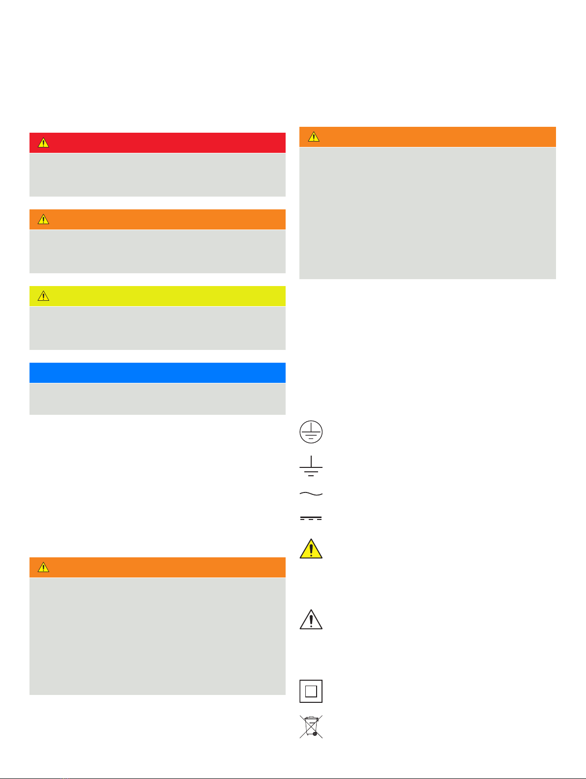
Product symbols .................................. 4
Product recycling and disposal
(Europe only).......................................5
End-of-life battery disposal ...................5
2011/65/EU (RoHS II) ...............................5
Cleaning ...........................................5
2 Cyber security...............................5
Communication protocol specific..............5
3 Overview....................................6
4 Mechanical installation.......................6
Transmitter installation............................ 6
Optional accessories..........................6
Location .....................................6
Sensor installation ................................ 6
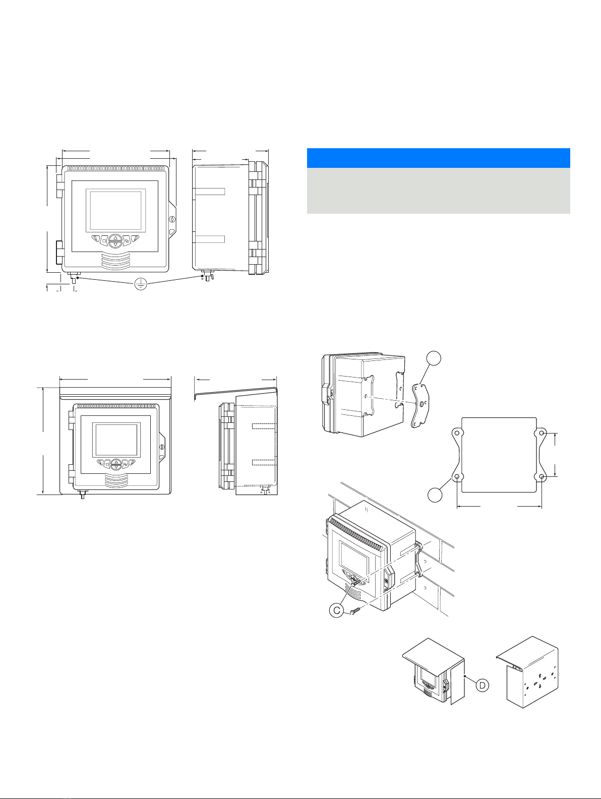
Transmitter dimensions.......................7
Optional weathershield dimensions............7
Sensor modules ..............................7
Communication module.......................7
Wall-mounting................................7
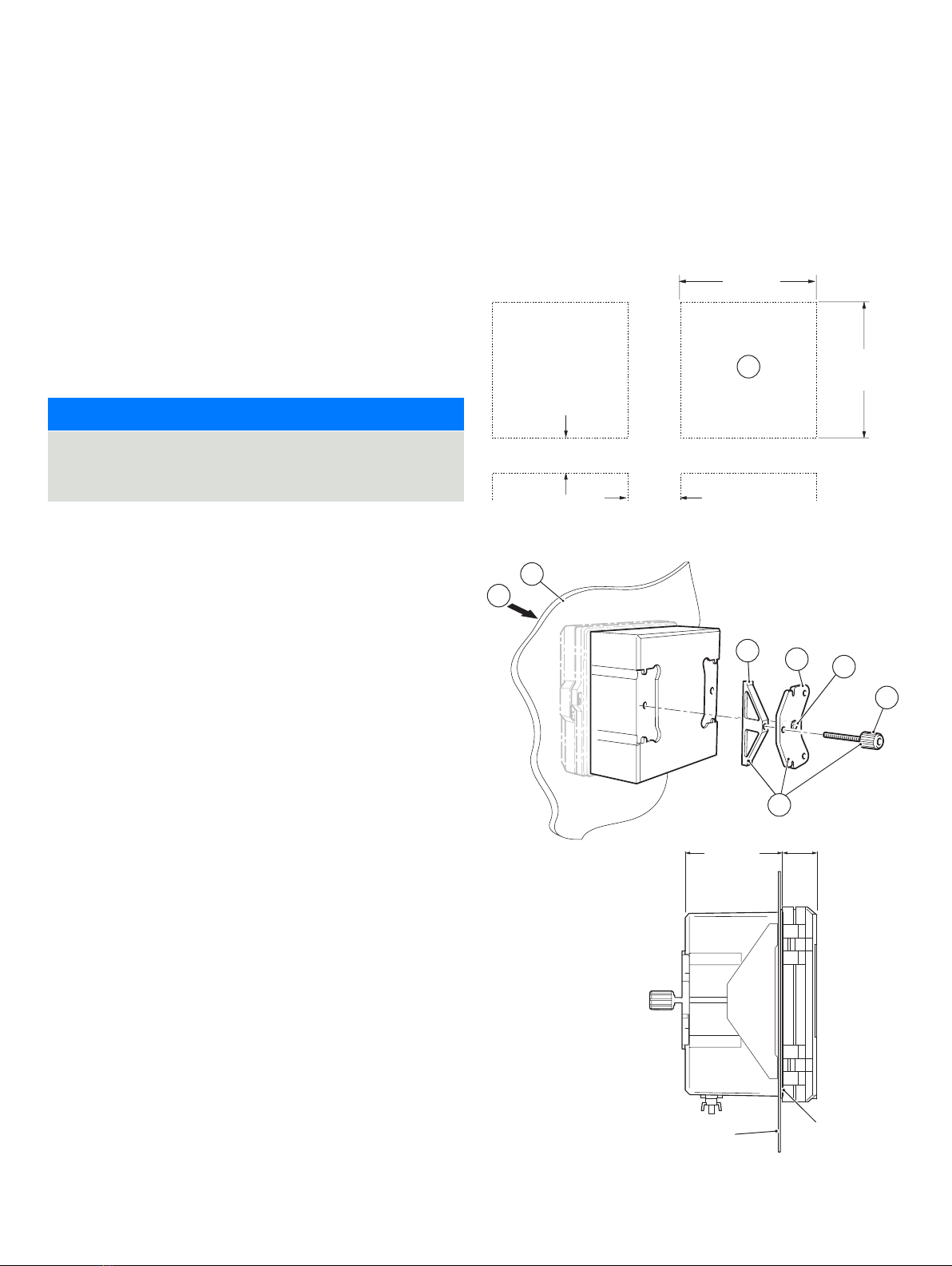
Panel-mounting (optional) ....................8
Pipe-mounting (optional) .....................9
5 Electrical installation ...................... 10
Earth bonding.....................................10
Cable entries......................................10
Terminal connections..............................11
...12
Conductivity sensor module connections ...........12
2-electrode sensors..........................12
4-electrode sensors .........................12
pH and conductivity connections ..................13
pH/ORP/pIon sensor module connections.....13
Power supply connection ..........................14
Fitting the EZLink modules ........................16
Connecting EZLink sensors ........................18
Long cables .................................18
6 Easy Setup .................................18
7 Operation ..................................19
Front panel keys...................................19
Modes of operation .............................. 20
Operator menus.................................. 20
Operating modes .................................21
View mode....................................... 23
............................23
Signals View.................................23
Chart View ..................................23
Alarms View .................................23
Outputs View................................23
Log mode........................................ 24
Log entries ...................................... 24
8 Data logging .............................. 25
Removable SD card ..............................25
Removable media ................................ 25
.................... 25
9 Password security and Access Level......... 26
Setting passwords ............................... 26
Access Level ..................................... 26
10 Sensor setup ...............................27
2-electrode conductivity...........................27
dual input calculated values setup ................. 28
4-electrode conductivity ......................... 29
pH/Redox/ORP .................................. 30
..............................................31
Turbidity/Suspended solids .......................31
11 Specification ...............................32
Operation........................................ 32
Mechanical data .................................. 32
Security ......................................... 32
Electrical ........................................ 32
Analog outputs. . . . . . . . . . . . . . . . . . . . . . . . . . . . . . . . . . . 32
Relay outputs .................................... 32
.............................. 32
Connectivity/Communications (optional).......... 33
..................................... 33
Environmental data .............................. 33
2-electrode conductivity.......................... 33
4-electrode conductivity ......................... 34
pH/ORP (Redox) ................................. 34
EZLink ........................................... 35
EMC ............................................. 35
Approvals, certification and safety ................ 35

AWT420 | UNIVERSAL 4-WIRE, DUAL-INPUT TRANSMITTER | CI/AWT420-EN REV. B 3
12 Spares .....................................37
Sensor module assemblies.........................37
AWT420 pH PCB upgrade/spares kit ..........37
AWT420 2-electrode conductivity
PCB upgrade/spares kit ......................37
AWT420 4-electrode conductivity
PCB upgrade/spares kit ......................37
EZLink module assemblies .........................37
AWT420 EZLink PCB upgrade/spares kit ......37
Communications module assemblies ...............37
AWT420 HART PCB upgrade/spares kit........37
AWT420 Profibus PCB upgrade/spares kit.....37
AWT420 Modbus PCB upgrade/spares kit .....37
AWT420 Ethernet PCB upgrade/spares kit.....37
AWT420 analog output PCB upgrade/
spares kit ...................................37
Mounting kits .................................... 38
Panel-mount kit .............................38
Pipe-mount kit ..............................38
Wall-mount kit...............................38
Weathershield kits ............................... 38
Weathershield kit ............................38
Weathershield and pipe-mount kit ............38
Gland packs/EZLink connectors................... 38
Gland packs .................................38
EZLink connector assembly ..................38

4AWT420 | UNIVERSAL 4-WIRE, DUAL-INPUT TRANSMITTER | CI/AWT420-EN REV. B
1 Health & Safety
Document symbols
Symbols that appear in this document are explained below:
DANGER
The signal word ‘DANGER’ indicates an imminent danger.
Failure to observe this information will result in death or
severe injury.
WARNING
The signal word ‘WARNING’ indicates an imminent danger.
Failure to observe this information may result in death or
severe injury.
CAUTION
The signal word ‘CAUTION’ indicates an imminent danger.
Failure to observe this information may result in minor or
moderate injury.
NOTICE
The signal word ‘NOTICE’ indicates potential material
damage.
Note
‘Note’ indicates useful or important information about the
product.
Safety precautions
Be sure to read, understand and follow the instructions
contained within this manual before and during use of the
equipment. Failure to do so could result in bodily harm or
damage to the equipment.
WARNING
Bodily injury
Installation, operation, maintenance and servicing must be
performed:
• by suitably trained personnel only
• in accordance with the information provided in this
manual
• in accordance with relevant local regulations
Potential safety hazards
AWT420 transmitter – electrical
WARNING
Bodily injury
To ensure safe use when operating this equipment, the
following points must be observed:
• Up to 240 V AC may be present. Be sure to isolate the
supply before removing the terminal cover.
Safety advice concerning the use of the equipment
described in this manual or any relevant Material Safety
Company, together with servicing and spares information.
Safety standards
This product has been designed to satisfy the requirements of
IEC61010-1:2010 3rd edition ‘Safety Requirements for Electrical
Equipment for Measurement, Control and Laboratory Use’ and
complies with US NEC 500, NIST and OSHA.
Product symbols
Symbols that may appear on this product are shown below:
Protective earth (ground) terminal.
Functional earth (ground) terminal.
Alternating current supply only.
This symbol, when noted on a product, indicates a
potential hazard which could cause serious personal
injury and/or death. The user should reference this
instruction manual for operation and/or safety
information.
This symbol, when noted on a product enclosure or
barrier, indicates that a risk of electrical shock and/or
electrocution exists and indicates that only
individuals qualified to work with hazardous voltages
should open the enclosure or remove the barrier.
The equipment is protected through double
insulation.
Recycle separately from general waste under the
WEEE directive.

AWT420 | UNIVERSAL 4-WIRE, DUAL-INPUT TRANSMITTER | CI/AWT420-EN REV. B 5
Product recycling and disposal
(Europe only)
ABB is committed to ensuring that the risk of any
environmental damage or pollution caused by any of
its products is minimized as far as possible. The
European Waste Electrical and Electronic Equipment
August 13 2005 aims to reduce the waste arising from
electrical and electronic equipment; and improve the
environmental performance of all those involved in
the life cycle of electrical and electronic equipment.
In conformity with European local and national
regulations, electrical equipment marked with the
above symbol may not be disposed of in European
public disposal systems after 12 August 2005.
NOTICE
For return for recycling, please contact the equipment
manufacturer or supplier for instructions on how to return
end-of-life equipment for proper disposal.
End-of-life battery disposal
The transmitter contains a small lithium battery (located on the
processor/display board) that must be removed and disposed
of responsibly in accordance with local environmental
regulations.
Information on ROHS Directive 2011/65/EU
(RoHS II)
ABB, Industrial Automation, Measurement &
Analytics, UK, fully supports the objectives of the
ROHS II directive. All in-scope products placed on the
market by IAMA UK on and following the 22nd of July
2017 and without any specific exemption, will be
compliant to the ROHS II directive, 2011/65/EU.
Cleaning
The complete transmitter can be hosed down if it has been
installed to IP66/NEMA 4X standards, i.e. cable glands are
correctly fitted and all unused cable entry holes are blanked off
page 11 and page 10.
Warm water and a mild detergent can be used.
2 Cyber security
This product is designed to be connected to and to
communicate information and data via a digital communication
interface. It is your sole responsibility to provide and
continuously ensure a secure connection between the product
and your network or any other network (as the case may be).
You shall establish and maintain any appropriate measures
(such as but not limited to the application of authentication
measures etc.) to protect the product, the network, its system
and the interface against any kind of security breaches,
unauthorized access, interference, intrusion, leakage and/or
theft of data or information.
ABB Ltd and its affiliates are not liable for damages and/or
losses related to such security breaches, any unauthorized
access, interference, intrusion, leakage and/or theft of data
or information.
Communication protocol specific
The HART protocol is an unsecured protocol, as such the
intended application should be assessed to ensure that these
protocols are suitable before implementation.
The Modbus protocol is an unsecured protocol, as such the
intended application should be assessed to ensure that these
protocols are suitable before implementation.
The PROFIBUS PA protocol is an unsecured protocol, as such
the intended application should be assessed to ensure that
these protocols are suitable before implementation.
the intended application should be assessed to ensure that
these protocols are suitable before implementation.
Other manuals for AWT420
3
Table of contents
Other ABB Transmitter manuals

ABB
ABB AW400 Series User manual

ABB
ABB AquaMaster4 User manual

ABB
ABB TB82EC User manual

ABB
ABB Industrial IT enabled 2600T Series User manual

ABB
ABB LST300 Series Operating and installation instructions

ABB
ABB 2600T Series User manual

ABB
ABB TTH300 Series User manual

ABB
ABB AWT420 User manual

ABB
ABB TTH300 Series User manual

ABB
ABB 265GS User manual
Popular Transmitter manuals by other brands

Geo
Geo Web Pack quick start guide

Inovonics
Inovonics EchoStream EN1210W installation instructions

IKONNIK
IKONNIK KA-6 quick start guide

Rohde & Schwarz
Rohde & Schwarz SR8000 Series System manual

Audio Technica
Audio Technica UniPak ATW-T93 Installation and operation

NIVELCO
NIVELCO EasyTREK SCA-300 Series Programming manual