PRG OHM LIGHT User manual

SOFTWARE VERSION 1.12
WWW.PRG.COM
OHM™LIGHT
USER MANUAL

AutoPar®, Bad Boy®, PRG Series 400®, Mbox Extreme®, OHM™, V476™, V676™, Virtuoso®, Virtuoso® DX, Virtuoso® DX2,
and VL6C+™ are trademarks of Production Resource Group, LLC, registered in the U.S. and other countries.
Gekko kleer colour® logo and Gekko kleer colour technology are trademarks of Gekko Technology Limited.
All other brand names which may be mentioned in this manual are trademarks or registered trademarks of their respective companies.
This manual is for informational use only and is subject to change without notice. Please check www.prg.com for the latest version.
PRG assumes no responsibility or liability for any claims resulting from errors or inaccuracies that may appear in this manual.
OHM™ Light User Manual
Version as of: October 6, 2011
Production Resource Group
Los Angeles Office
9111 Sunland Blvd.
Sun Valley, California 91352
www.prg.com
OHM™ Light User Manual
©2011 Production Resource Group, LLC. All Rights Reserved.

OHM™ LIGHT USER MANUAL 1
IMPORTANT INFORMATION
Safety Information
The symbols below are used throughout this manual to identify important safety information.
Heed all warnings and safety information.
Changes
PRG provides this manual 'as is' without warranty of any kind, either expressed or implied, including but not limited to
the implied warranties or merchantability and fitness for a particular purpose. PRG may make improvements and/or
changes to the product(s) and/or the program(s) described in this publication at any time without notice.
This publication could contain technical inaccuracies or typographical errors. Changes are periodically made to the
information in this publication; these changes are incorporated in new editions of this publication.
Measuring Correlated Color Temperature (CCT)
The OHM Light utilizes an LED source that is optimized for the film, TV, and image capture industries. Current color
meters cannot be used to accurately read the correlated color temperature (CCT) of OHM and other discontinuous-
spectrum light sources.
Color meters in use today are designed for a full spectrum source such as incandescent lights. These meters possess
only 3 sensors to measure the light output: red, green, and blue. As such, a narrow band light source, such as OHM
may not read correctly.
PRG and Gekko Technology have taken great care in ensuring that the CCT of the light emanating from OHM matches
traditional light sources. This allows you to easily place OHM alongside your traditional lighting fixtures.
If in any doubt, it is the users responsibility, as is customary, to shoot image capture tests when combining sources
using different core technology such as HMI, florescent, tungsten or simple RGB LED fixtures to ensure compatibility.
SYMBOL MEANING
Warning, Danger or Caution
Risk of injury to yourself or the product.
Risk of Electrical Shock
Risk of severe electrical shock.
Risk of Electrical Shock. No serviceable parts inside.
Observe all local and national electrical and environmental codes.
The socket-outlet shall be installed near the equipment and shall be easily accessible.
WARNING

2OHM™ LIGHT USER MANUAL
TABLE OF CONTENTS
Introduction
About This Manual........................................................................................................................................................................ 3
Additional Documentation ............................................................................................................................................................ 3
Customer Service ......................................................................................................................................................................... 4
User Instructions
General Notes............................................................................................................................................................................... 5
Fixture Set Up............................................................................................................................................................................... 5
Ventilation ..................................................................................................................................................................................... 5
Additional Safety Considerations ................................................................................................................................................. 6
Cleaning........................................................................................................................................................................................ 6
Power Supply ............................................................................................................................................................................... 6
Fixture Overview
OHM Components and Controls .................................................................................................................................................. 7
Spare Parts/Accessories
Individual Parts List ...................................................................................................................................................................... 8
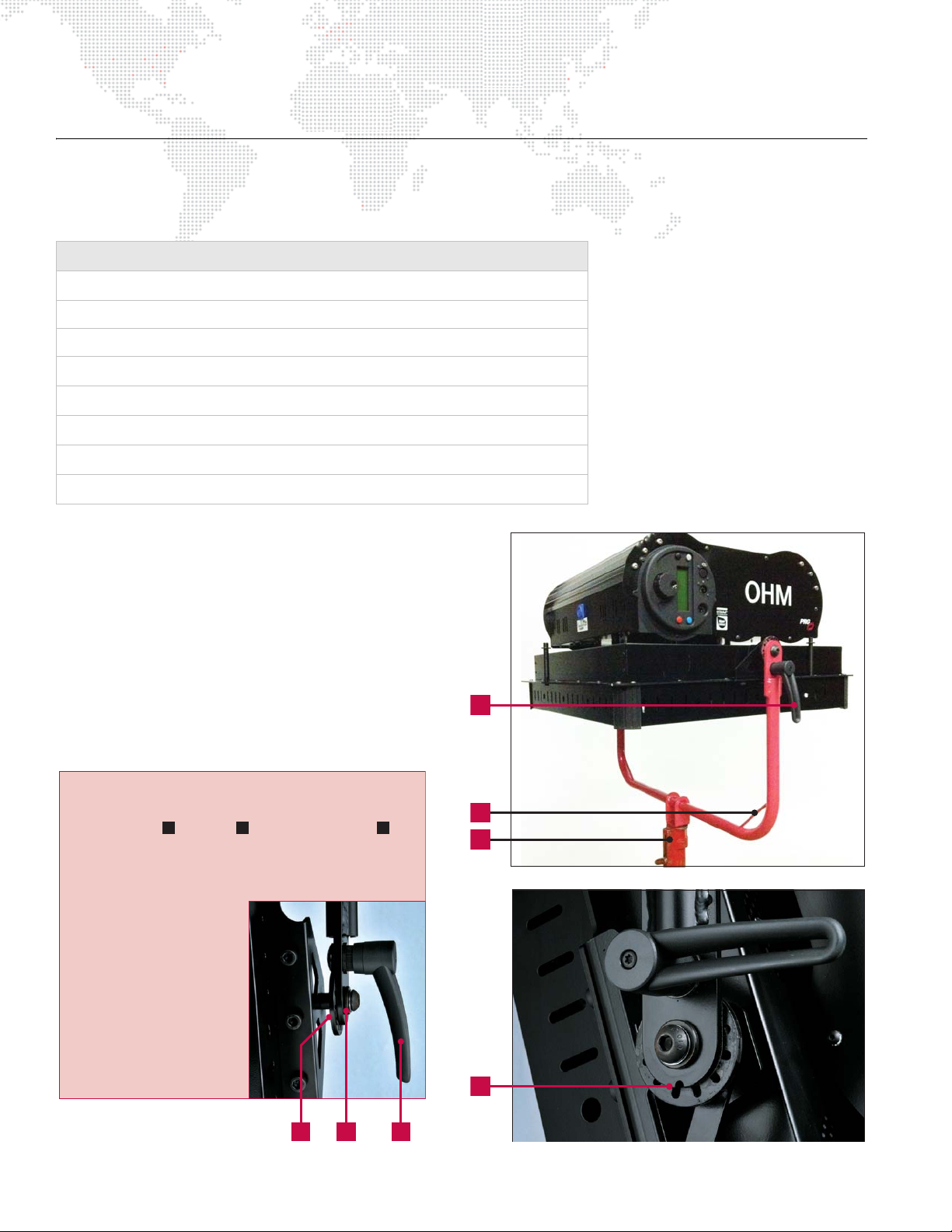
Mounting Options ......................................................................................................................................................................... 8
Yoke ...................................................................................................................................................................................... 8
Spigot/Lifting Eye .................................................................................................................................................................. 9
Hanger Assembly .................................................................................................................................................................. 9
Safety Cable (not provided)................................................................................................................................................... 9
Powering Options ....................................................................................................................................................................... 10
Neutrik Power Cable Connector.......................................................................................................................................... 10
Accessory Options ..................................................................................................................................................................... 10
Accessory Skirts.................................................................................................................................................................. 10
Operation
Connection Ports........................................................................................................................................................................ 11
DMX Connections....................................................................................................................................................................... 11
MMI Controls .............................................................................................................................................................................. 11
Functions:............................................................................................................................................................................ 11
Default Control Screen: ....................................................................................................................................................... 12
Navigation Through '1st Level' Menus ................................................................................................................................ 13
Navigation Within 'Color CCT' Menu .................................................................................................................................. 14
Navigation Within 'Color Gekko' Menu ............................................................................................................................... 15
Navigation Within 'DMX Address' Menu ............................................................................................................................. 15
Navigation Within 'DMX Mode' Menu ................................................................................................................................. 16
Navigation Within 'Information' Menu ................................................................................................................................. 16
Navigation Within 'Maintenance' Menu............................................................................................................................... 17
DMX Controls ............................................................................................................................................................................. 17
OHM - 'Standard' DMX Control (2 Channels) ..................................................................................................................... 18
OHM - 'Advanced' DMX Control (10 Channels) .................................................................................................................. 18
DMX Control: Application Example ............................................................................................................................................ 19
For OHM 'Standard' DMX Control: ..................................................................................................................................... 19
For OHM 'Advanced' DMX Control: .................................................................................................................................... 19
OHM IS RDM ENABLED!..................................................................................................................................................... 20
Specifications
Power Characteristics................................................................................................................................................................. 21
Physical Characteristics ............................................................................................................................................................. 21
Optical Characteristics ............................................................................................................................................................... 21
Warnings and Cautions .............................................................................................................................................................. 22

OHM™ LIGHT USER MANUAL 3
INTRODUCTION
About This Manual
This manual provides installation, operation, and maintenance instructions for the OHM™ Light.
This manual applies to the following software versions:
+ MMI: 1.12
+ Driver Board: 1.08
Familiarizing yourself with this information will help you get the most out of your PRG product.
Additional Documentation
For more information regarding DMX512 systems, refer to the DMX512/1990 & AMX 192 Standards publication
available from United States Institute for Theatre Technology, Inc. (USITT).
USITT
6443 Ridings Road
Syracuse, NY 13206-1111 USA
1-800-93USITT
www.usitt.org

4OHM™ LIGHT USER MANUAL
Customer Service
For technical assistance, contact the PRG International Service Center or contact your nearest PRG office. Contact
information for all PRG office locations can be found on our website at: www.prg.com/about-us/locations/
PRG Dallas (International Service)
8617 Ambassador Row, Suite 120
Dallas, Texas 75247 USA
Phone: 214.630.1963
Fax: 214.630.5867
Service Fax: 214.638.2125
Service Email: orders@prg.com
For additional resources and documentation, please visit our website at: www.prg.com

OHM™ LIGHT USER MANUAL 5
USER INSTRUCTIONS
General Notes
1) Please read through this manual carefully before operating the OHM Light. Keep this manual for future reference.
2) There are numerous safety instructions and warnings that must be adhered to for your own safety.
3) OHM is not intended for residential use. It is only intended for use in a professional studio.
4) OHM must only be serviced by a qualified individual.
5) OHM is rated as IP20 - for indoor use and in a dry environment.
6) OHM is not certified for use in hazardous locations.
7) OHM's operation temperature is within the range of 0 to +50°C (32 to 104°F).
8) Use only approved spare parts and accessories. (Refer to "Spare Parts/Accessories" on page 8.)
Fixture Set Up
1) Read these safety instructions carefully to ensure OHM and accessories are used safely.
2) Ensure the 28mm Spigot or 12mm Lifting Eye is correctly mounted onto the yoke before rigging.
3) For an alternative method of hanging OHM, a Hanger Assembly is available as an accessory. Ensure this is
correctly attached to OHM before rigging.
4) Always use a suitable length safety cable(s) when hanging OHM. (Safety cables are not provided.) The length
should be as short as possible to reduce travel distance if the primary hanging accessory fails.
5) OHM weighs 32kg, excluding accessories. The combined weight should be considered when choosing a suitable
safety cable(s).
6) The safety cable(s) must be securely attached to the designated slots on OHM (detailed on page 9).
7) Ensure that the yoke locking handle is correctly tightened when manipulating OHM in the required orientation for
safety purposes. NOTE: if the locking handle is not tightened correctly, the fixture may swing.
8) Ensure the connection cables and any other cables are attached to the designated slots located on the yoke
corners (detailed on page 8).
9) It is the user's responsibility to provide and wire their own power cable using the Neutrik power cable connector
provided with OHM.
10) Ensure OHM is stored within the range of -20 to +60°C (-4 to 140°F).
Ventilation
1) Do not cover air ventilation slots on OHM or the fixture may overheat.
2) Do not use OHM outdoors or in a wet environment.
3) Keep OHM a minimal distance of 0.1m away from flammable materials/objects.

6OHM™ LIGHT USER MANUAL
Additional Safety Considerations
1) Do not open OHM when the fixture is powered.
2) Allow OHM to cool before servicing, as internal parts may be hot.
3) Do not alter the design of OHM or tamper with any of the safety features.
4) Do not look directly into OHM's bare light source as it may be harmful to the eyes.
5) OHM reaches a maximum surface temperature of 85ºC. Please ensure contact on the surface by persons or
materials is avoided when the fixture is operating.
6) Do not operate OHM if there are any signs of physical damage. In case of damage, it is advised that you contact
PRG service.
7) Before using OHM check for any of the following defects:
Cleaning
1) Clean optical front plate with suitable alcohol-based cleaner.
Power Supply
1) Ensure the power cable is disconnected before servicing.
2) OHM only uses a mains connection. Do not connect to a variable supply, such as a dimmer rack or inverter.
3) The power cable should be plugged into OHM before switching the mains power supply ON. The mains power
supply should be switched OFF before removing the power cable.
Note: OHM has been built to conform to International regulatory standards relating to professional lighting
equipment. Any modification made to OHM will void the manufacturers' warranty.
PART POSSIBLE DEFECT
Optics Physical damage, dull, burnt out
Power Cable Physical damage, cut, burnt
Locking Handle Physical damage, loose
Spigot/Lifting Eye Physical damage, loose, crack/split
Hanger Assembly Physical damage, loose lifting eye
Hanger Assembly -
Cables/Carabiners Physical damage, cut, frayed, carabiners loose or deformed
Safety Cable/s Physical damage, cut,
Ventilation Physical damage, covered
MMI Physical damage, unrecognizable screen
Yoke Physical damage, loose
Casing Physical damage

OHM™ LIGHT USER MANUAL 7
FIXTURE OVERVIEW
OHM Components and Controls
OHM is a powerful light fixture that incorporates sixteen of Gekko's high quality, kleer colour® LED arrays. This LED
source provides the user with a large volume of white light at a stable and repeatable CCT, emulating traditional
sources.
The OHM Light can be controlled via the
MMI (Man-Machine Interface) attached to
the side of the fixture, or via an external
DMX512 that can communicate with the
fixture through a control port located on
the local controls.
OHM Features:
[1] Optics/LED Source
[2] Yo ke
[3] Locking Handle
[4] Spigot/Lifting Eye
[5] Yoke Cable Slots
[6] Comms Port
[7] DMX In Port
[8] DMX Thru Port
[9] MMI (Man-Machine Interface)
[10] Neutrik Power Cable Port
MMI Controls for:
+ Color - CCT
+ Color - Gekko
+ DMX Address
+ DMX Mode
+ Information
+ Maintenance
10
1
2
3
4
5
6
7
8
9

8OHM™ LIGHT USER MANUAL
SPARE PARTS/ACCESSORIES
Individual Parts List
The following is a list of PRG accessory and replacement parts available for OHM:
Mounting Options
Yoke
[1] Locking Handle - turning counter-clockwise loosens
the yoke. Turning clockwise tightens the yoke.
[2] Cable Slots - cables should be secured to these
slots to ensure they do not come into contact with
OHM housing.
[3] Spigot/Lifting Eye
[4] Slots - indicate rigging angle and are set to 30º
increments.
CODE ITEM
Complete Kits:
757-300100 PRG OHM Light Fixture
757-300110 PRG OHM Hanger Assembly (Four Cables Included)
Mounting and Suspension:
757-300465 PRG OHM Spigot 28mm, Anti-Rotate w/Screw
757-300470 PRG OHM Lifting Eye, M12
757-300610 PRG OHM Hanger Frame
757-300615 PRG OHM Hanger Frame Cable
1
2
3
4
Locking Handle Relocation: continuously turning the
locking handle counter-clockwise will loosen/remove
the coach bolt , washer and locking handle .
CAUTION: OHM will be free to rotate once the locking
handle is removed. Please be careful when doing this.
Once removed, the
locking handle can be
relocated to the other
side of OHM for
convenience. This can
be done by ensuring
the washer and locking
handle are bolted onto
the coach bolt from
the outside.
CBA
A B C

OHM™ LIGHT USER MANUAL 9
Spigot/Lifting Eye
[1] 28mm Spigot - used to fix OHM into a 28mm
receiver.
[2] M12 Lifting Eye - used to hang OHM from a
single point.
[3] M12 x 1.5mm, 25mm Long Bolt - used to bolt
either the Spigot or the Lifting Eye to OHM.
Hanger Assembly
(Used to hang OHM from four points.)
[1] Mounted Lifting Eye
[2] Four Cables
[3] Carabiners
Safety Cable (not provided)
[1] Safety Cable - a minimum of one cable MUST be
used when hanging OHM. The length should be as
short as possible to reduce travel distance if the
primary hanging accessory fails.
[2] Safety Cable Slots - MUST be used to attach
safety cable(s) by looping through (as shown).
2
3
1
NOTE: tighten M12 bolt to 85Nm (63lbft).
Use minimum 8.8 grade bolt.
3
2
1
Safe Rigging of the
Hanger Assembly:
ensure the four holes
located in each corner of
OHM are the ONLY
holes used to secure OHM
to the Hanger Assembly.
Ensure the Carabiners are tightened correctly to
secure the cables to OHM through the four holes.
Also ensure the Carabiners are used and tightened
correctly to secure the cables to the hanger
assembly through the four holes.
A
A
2
1
Safe Use of Safety Cables: ensure the two oval
holes located at the top of OHM are the ONLY
holes used to secure the safety cable(s).
Ensure safety cable(s) are capable of supporting
the load exerted by OHM plus accessories.
2

10 OHM™ LIGHT USER MANUAL
Powering Options
Neutrik Power Cable Connector
OHM is fitted with a Neutrik PowerCon® NAC3 type
connector. Use only Neutrik PowerCon NAC3FCA connectors.
It is the user's responsibility to provide and wire their own
power cable using the Neutrik power cable connector
provided with OHM.
To wire connector:
Step 1. Slide bushing and chuck onto cable.
Step 2. Prepare cable as shown in Figure 1.
Step 3. Insert wire into terminals and fasten clamping
device using slotted screwdriver.
Step 4. Push insert and chuck into housing (pay attention to
the guiding keyway!).
Step 5. Fasten bushing by means of a fork wrench, 3/4" minimum. Torque 2.5 Nm (1.8 lb-ft).
Figure 1: Neutrik Power Cable Wiring
Accessory Options
Note: OHM-specific accessories are currently under development. Please contact your sales office for more info.
Accessory Skirts
Standard Space Light accessory skirts may be used with
OHM, if desired. These hang on the three accessory pillars
mounted on the chassis of the fixture.
ENGAGEMENT
SEPARATION
Da = 5.00 [0.197”] - 11.00 [0.433”]
white chuck
Da = 9.50 [0.374”] - 15.00 [0.59”]
black chuck
Housing Insert Chuck Housing

OHM™ LIGHT USER MANUAL 11
OPERATION
OHM provides control over the Intensity and CCT (Correlated Color Temperature). These variables can be controlled
directly from the MMI located on the side of the fixture, or via DMX.
Connection Ports
Connections are as follows:
[1] Comms Port: This port allows for software
updates.
[2] DMX In: Data in via DMX512 protocol.
[3] DMX Thru: Data out via DMX512 protocol.
[4] Power In (AC): The Neutrik power cable will
connect to OHM via this port.
DMX Connections
OHM uses industry standard 5-Pin XLR male and female connectors to receive DMX signals and output DMX signals.
The DMX Pin wiring is as follows:
+ Pin 1: Ground
+ Pin 2: Data -
+ Pin 3: Data +
+ Pin 4: Spare
+ Pin 5: Spare
Note: OHM is self-terminating and does not require external DMX termination when used in a chain.
MMI Controls
Functions:
[1] Rotary Knob: Navigates forwards &
backwards through the menus/pages and
also used to alter values.
[2] Black Button: Used to select and also turn
light output ON or OFF.
[3] Grey Button: Not required for use of OHM.
[4] Blue Button: Currently disabled.
[5] Red Button: Used to access the 1st level
menus.
[6] Display Screen: Displays menu options and
status.
1
2
3
4
4
3
2
1
56

12 OHM™ LIGHT USER MANUAL
Default Control Screen:
[1] Rotary Knob: Alters the intensity of the set CCT
from 0%-100%.
[2] Black Button: Switches the light source OFF
(NOTE: the MMI remains ON).
[3] Grey Button: Currently disabled.
[4] Blue Button: Currently disabled.
[5] Red Button: Accesses the 1st level menus.
[A] CCT Title: The 1st line indicates the set CCT.
[B] CCT Detail: The 2nd line provides detail
regarding the set CCT.
[C] Intensity Bar: Visual representation of the
current intensity setting.
[D] Intensity %: Numerical representation of the
current intensity setting.
[E] DMX Address: Displays the current DMX
Address set to the fixture.
[F] Button Description: The corresponding
function will be displayed next to the button on
the screen. NOTE: If there is no text, this
indicates the button has no function.
White CCT
2900K Studio
ON 100% DMX451 MENU
White CCT
2900K Studio
ON 100% DMX451 MENU
2
3 4
51
The Man-Machine Interface (MMI) consists of
numerous menus that control the fixture. When
powering OHM, the default control screen will
become active on the MMI.
C
B
A
D E F
The MMI screen backlight activates on user
interaction and deactivates after a few seconds.

OHM™ LIGHT USER MANUAL 13
Navigation Through '1st Level' Menus
Colour CCT
SELECT
Colour Gekko
SELECT
DMX Address
SELECT
DMX Mode
SELECT
Information
SELECT
Maintenance
SELECT
White CCT
2900K Studio
ON 100% DMX451 MENU
SCROLL
NOTE: 2 clicks are required to cycle
back to the initial control screen
1
2
3
4
5
6

14 OHM™ LIGHT USER MANUAL
Navigation Within 'Color CCT' Menu
Once the required CCT is selected, the corresponding control screen will open.
This example shows the 2900K CCT control screen.
White CCT
2900K Studio
ON 100% DMX451 MENU
Colour CCT
SELECT
Colour CCT
2900K Studio
SELECT MENU
Colour CCT
3200K Tungsten
SELECT MENU
1
Continuous scrolling will show every option.

OHM™ LIGHT USER MANUAL 15
Navigation Within 'Color Gekko' Menu
Once the required CCT is selected, the corresponding control screen will open.
This example shows the 2900K CCT control screen.
Note: This menu is empty upon delivery of OHM. Contact PRG for Gekko kleer colour bespoke colors.
Navigation Within 'DMX Address' Menu
Once the required DMX address is selected, the current control screen will re-open.
This example shows the 2900K CCT control screen.
Colour Gekko
SELECT
Gekko gel 123
Special steel blue
SELECT MENU
Gekko gel 123 HLD
Special steel blue
OFF 50% DMX123 MENU
2
Continuous scrolling will show every programmed Gekko colour.
DMX Address
SELECT
DMX base channel
123
SELECT MENU
3
The Rotary Knob will scroll through numbers 001-512
to allow the user to set the required DMX Address.
White CCT
2900K Studio
ON 100% DMX451 MENU

16 OHM™ LIGHT USER MANUAL
Navigation Within 'DMX Mode' Menu
Once the required DMX Mode is selected, the current control screen will re-open.
This example shows the 2900K CCT control screen.
Navigation Within 'Information' Menu
If any button is pressed, the current control screen will re-open.
This example shows the 2900K CCT control screen.
DMX Mode
SELECT
DMX Mode
Standard
SELECT MENU
DMX Mode
Advanced
SELECT MENU
4
White CCT
2900K Studio
ON 100% DMX451 MENU
Information
SELECT
5
OHM
Serial No XXXXXXXXX
Customer No XXXXXXX
Running hrs 12345.6
White CCT
2900K Studio
ON 100% DMX451 MENU

OHM™ LIGHT USER MANUAL 17
Navigation Within 'Maintenance' Menu
If any button is pressed, the current control screen will re-open.
This example shows the 2900K CCT control screen.
Note: When OHM is powered down via the mains, the MMI will switch OFF. When OHM is powered up, the fixture will
remember the last MMI settings: Intensity, CCT, DMX Mode and DMX Address.
DMX Controls
Once the DMX is connected to OHM via the 'DMX In' port, the fixture can be controlled by the DMX. The MMI will
display the DMX control screen as shown below:
[1] DMX Mode Setting: The 1st line displays current
DMX Mode.
[2] Current DMX Address: The 2nd line displays
current DMX Address.
[3] New DMX Address: The 3rd line displays a new
DMX Address, should the user want to change the
current DMX Address. The new address can be
altered by using the Rotary Knob.
[4] Black Button: Once the new DMX Address has
been altered via use of the Rotary Knob, the user
can confirm this change by selecting the Black
Button. This will change the Current DMX Address
to the value chosen in the New DMX Address.
[5] Red Button: This button and all others remain
inactive when connected to a DMX
Maintenance
SELECT
6
Maintenance
When the Maintenance option is selected, OHM functions in Maintenance Mode. This mode allows
the connection to the internal electronics via use of the Communications Port. Software updates will
be carried out when in this mode.
White CCT
2900K Studio
ON 100% DMX451 MENU
Mode = Standard
Current DMX 001
New DMX 003
SELECT
4 53
1 2

18 OHM™ LIGHT USER MANUAL
Depending on the DMX Mode assigned through the MMI the DMX controls are as follows:
OHM - 'Standard' DMX Control (2 Channels)
+ DMX Channel 1 = Master Intensity (DMX value 0-255 = level 0-100%)
+ DMX Channel 2 = CCT Color Wheel:
OHM - 'Advanced' DMX Control (10 Channels)
+ DMX Channel 1 = Master Intensity (DMX value 0-255 = level 0-100%)
+ DMX Channel 2 = CCT Color Wheel:
+ DMX Channel 3 = Gekko Gel Color Wheel:
+ DMX Channel 4 = Decimal 100s
+ DMX Channel 5 = Decimal 10s
+ DMX Channel 6 = Decimal units
Note: When the Gekko Gel Color Wheel is switched on by the corresponding channels, the decimal channels are
used to input a specific number (e.g., 219).
2900K 3200K 3600K 4300K 5000K 5600K 6500K
OHM DMX 0 37 75 110 146 182 218
-------
36 74 109 145 181 217 255
2900K 3200K 3600K 4300K 5000K 5600K 6500K
OHM DMX 0 37 75 110 146 182 218
-------
36 74 109 145 181 217 255
GEKKO GEL SELECTION OFF GEKKO GEL SELECTION ON
OHM DMX 0-217 128-255
0-
25
26-
50
51-
75
76-
100
101-
125
126-
150
151-
175
176-
200
201-
225
226-
255
Ch 4 - Decimal (100s) 0 100 200 300 400 500 600 700 800 900
Ch 5 - Decimal (10s) 0 102030405060708090
Ch 6 - Decimal (units) 0123456789
Table of contents
Other PRG Lighting Equipment manuals