ADVANTAGE - DIGITAL VAV DIFFUSERS
PRODUCT OVERVIEW & INSTALLATION INSTRUCTIONS
7
acutherm.com |ACUTHERM ADVANTAGE - Manual
PRODIGY®- PERSONAL SELF-MODULATING DIFFUSERS
PRODUCT OVERVIEW & INSTALLATION INSTRUCTIONS
Acutherm Power Module Optional Accessory
The Advantage Power Module (APM) supports up to fifteen*
(15) Advantage diffusers (Masters plus Drones). It provides the
most economical and convenient method of powering multiple
Advantage diffusers because electrician time is minimized.
Designed to be ceiling mounted, the enclosed 96 VA Class 2
transformer is offered for 120V, 240V, 277V and 480V primary
voltage supply. Final power connections to the Advantage
diffusers are completed via plenum cables with RJ (Snap-In)
plugs. Since the cables are all low voltage, commissioning or
relocation of Advantage diffusers is simple.
*See CAUTION pg 6 if using Aux heat option.
Features
• 96 VA Class 2 Transformer (120 / 240/277/480 to 24 VAC)
with breaker resettable overload protection.
• 6 parallel power jacks each of which support up to 6
Advantage units (or PIC controllers) - any combination of
masters and associated drones. Overload indicator LEDs
on each line light up if too many Advantage diffusers (or
PIC’s) are connected or if there is a short in the cable.
• Max 15 Advantage diffusers or PIC controllers per APM
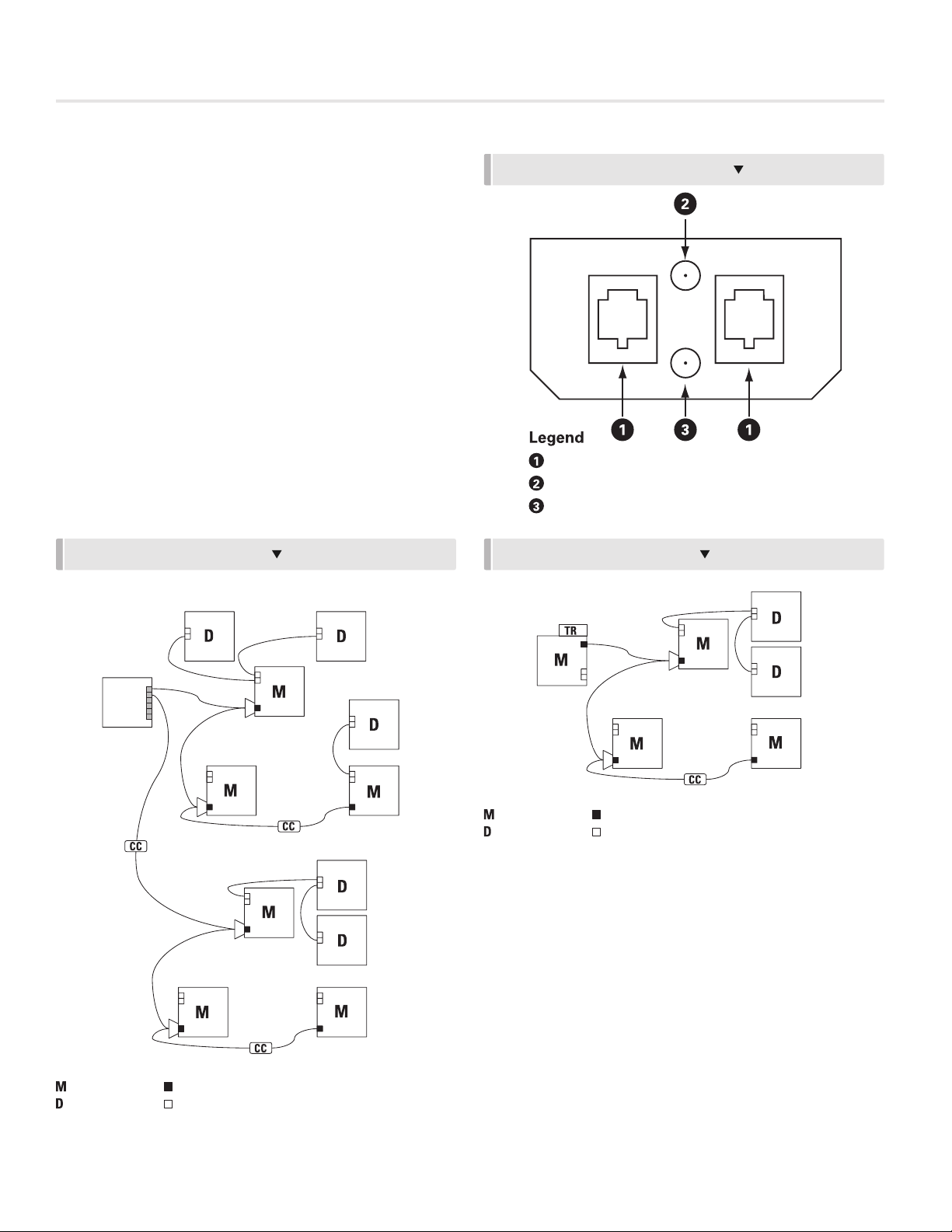
• C35 (35’ plenum rated cable) with RJ plugs provides
flexible and convenient power connection. One required
for each master unit (order separately). Multiple cables can
be connected by using a CC (Cable Connector) for longer
runs. (Fig. 6 page 3.) 210ft maximum.
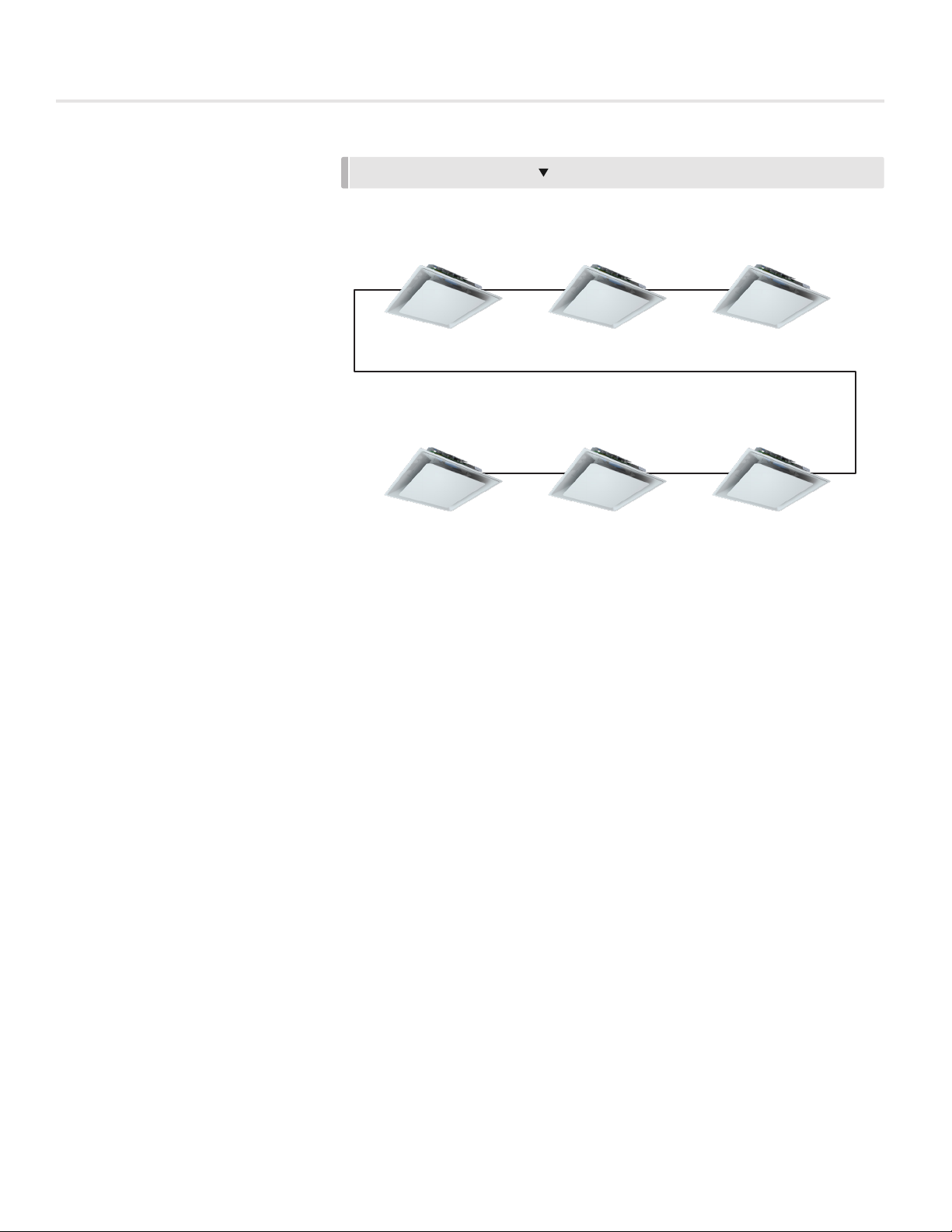
• CSJ Cable Splitters used to daisy chain power between
masters. (Fig. 6 page 3.)
• Power switch with indicator LED.
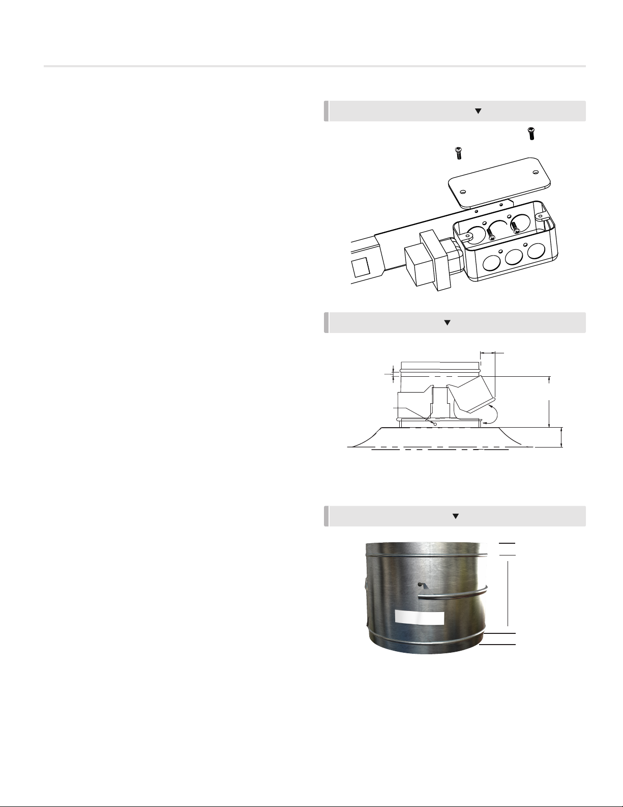
Installation Instructions
1. Turn off power switch. Remove cover.
2. Secure box to surface in plenum using 3 mounting holes.
Orientation irrelevant.
3. Supply power and ground to terminal per wiring diagram.
4. Replace cover.
5. Turn on power switch. Green LED indicates power
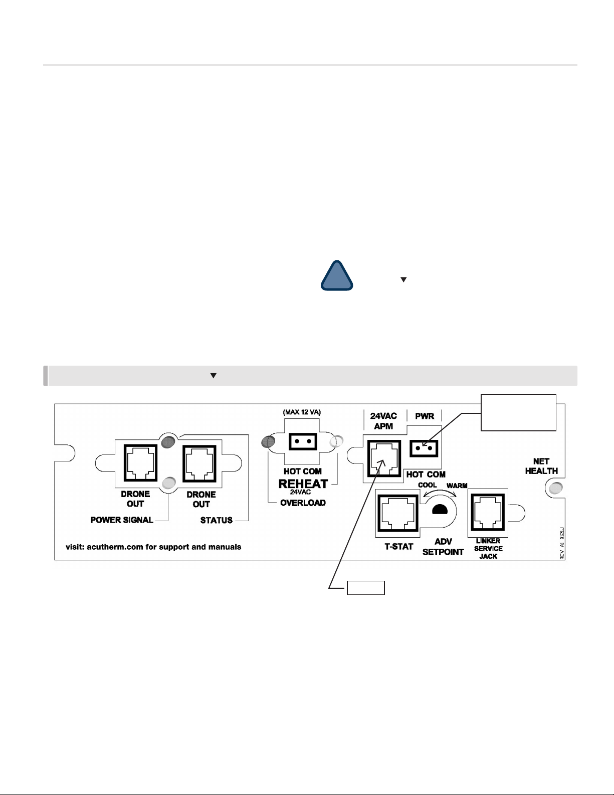
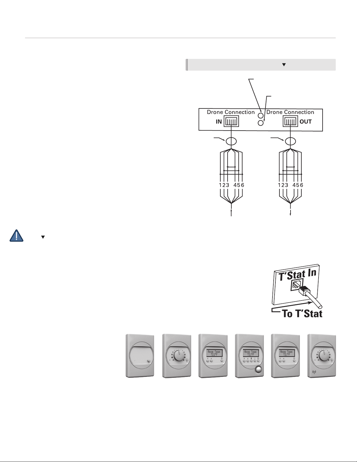
Connecting a Advantage Master to the APM
1. Plug C35 power cable into an output jack on power
module.
2. Plug other end of cable into power input jack of Advantage
Master Junction Panel. (Multiple C35 cables can be
connected with CC - Cable Connectors for longer runs.)
(Max two 35 ft cables)
3. Green Power LED and Red Drone Signal LED on
Advantage Master indicate proper connection.
4. An additional Master unit may be supported from second
side of an optional CS (cable splitter) inserted into the
Advantage Master power input jack. (see Fig. 6 page 3).
Specification and Limitations
1. Total connected load not to exceed 96 VA (or 15 devices)
• Each Advantage unit (Master or Drone) draws 3.0 VA.
• See CAUTION pg 6 if using Aux heat option.
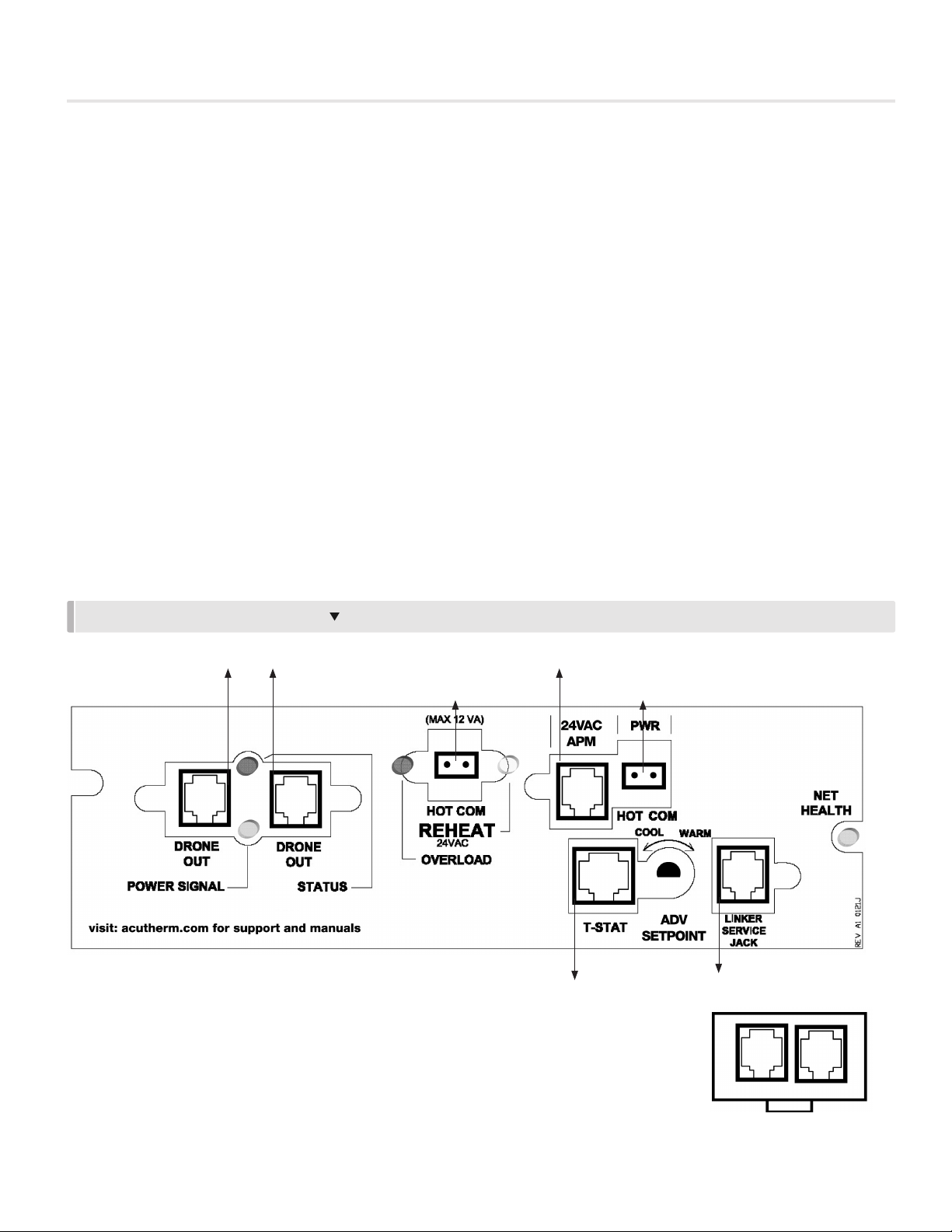
2. Specification for each of the 6 output jacks:
• 20 VA auto-reset thermal fuse with fault indicator LED.
• Supports up to 6 Advantage diffusers up to a
maximum distance of 210’ from the APM
• Supports only one mechanical relay (12 VA max.) for
aux. heat output up to a maximum distance of 35’.
(No limitation applies to electronic solid state.)
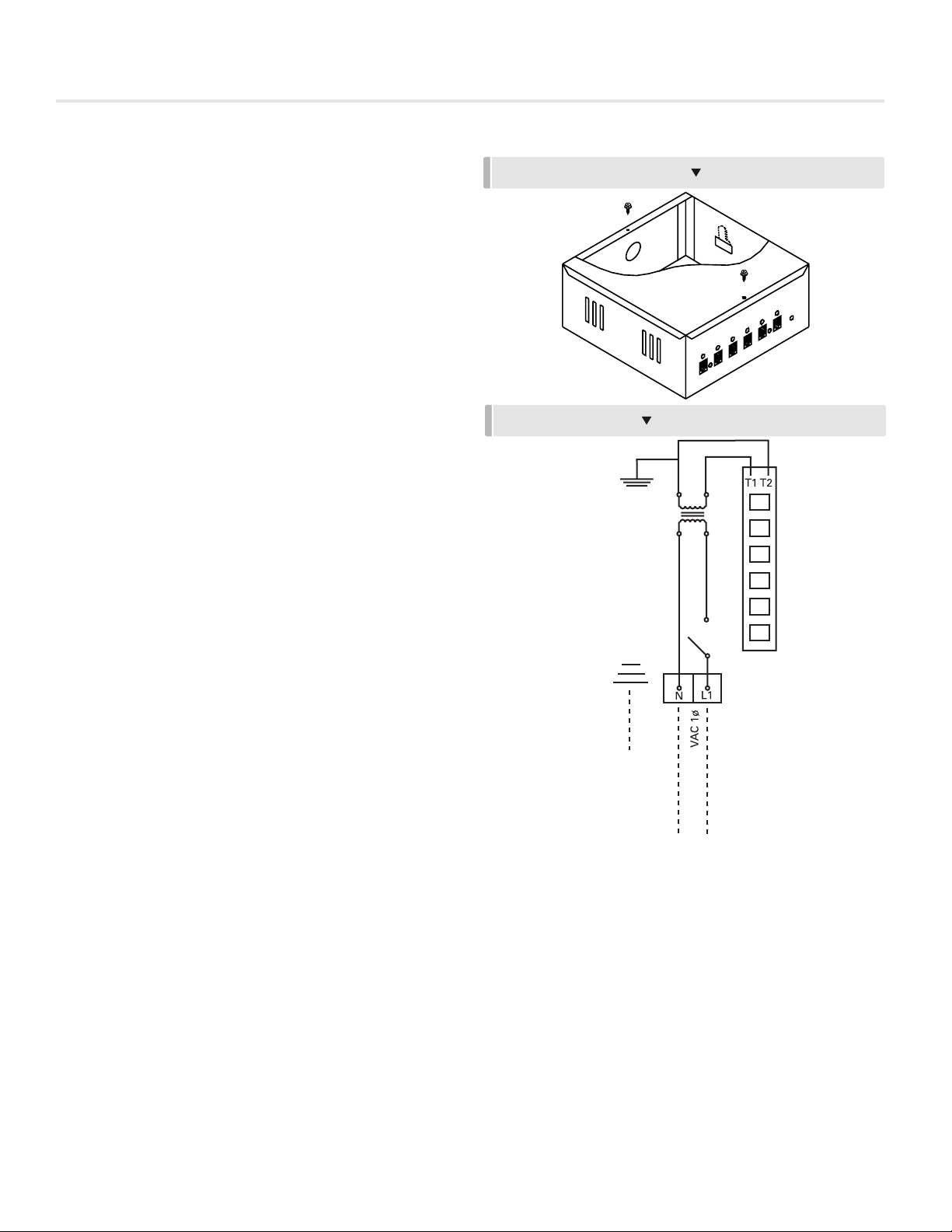
ADVANTAGE POWER MODULE
MUST BE EARTH
GROUNDED
120/240/277/480
OUTPUT BOARD
TERMINAL
BLOCK
96 VA
TRANSFORMER
DISCONNECT
SWITCH
GROUND
APM CONNECETIONS