2ULTRASUITE ARRAY - Manual |priceindustries.com
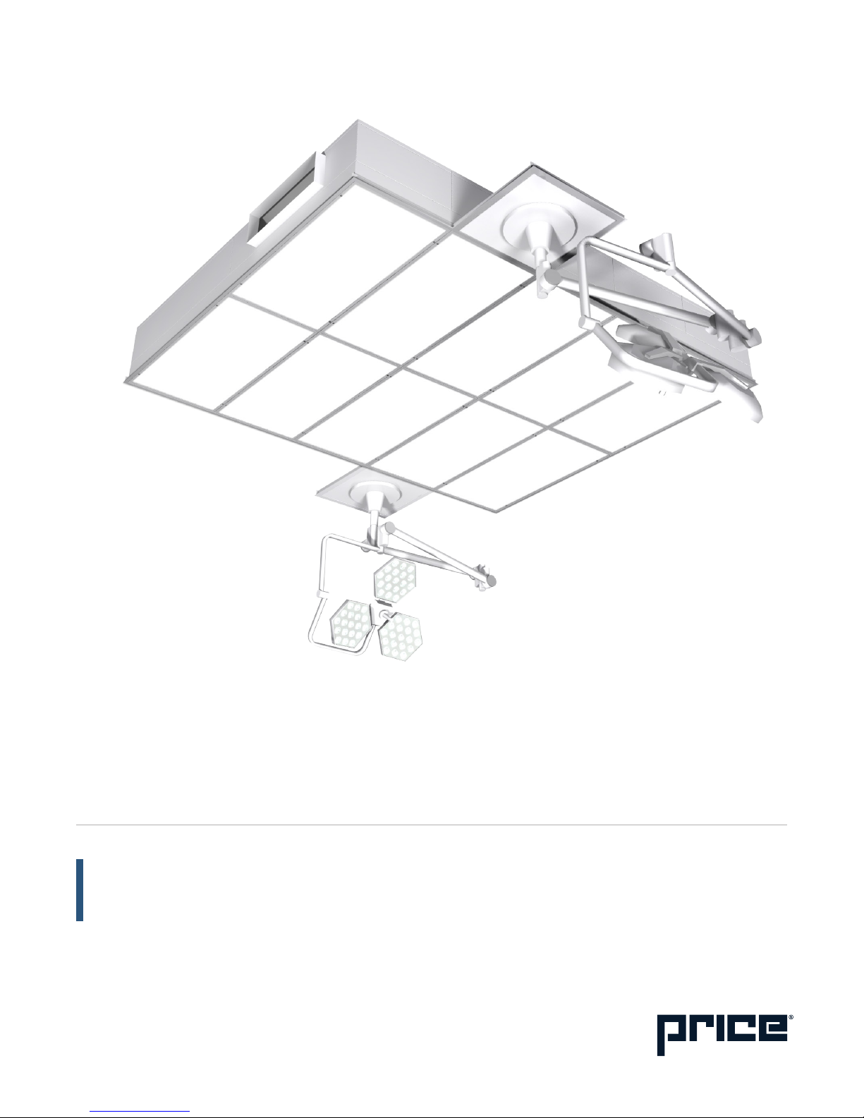
ULTRASUITE ARRAY
PRE-INSTALLATION INSTRUCTIONS AND CHECKLIST
Read and Save These Instructions
Warning
• To reduce the risk of fire, electrical shock, or injury to persons, observe the following:
• Installation work and electrical wiring must be done by a qualified person(s) in accordance with all applicable codes
and standards, including fire-rated construction.
• Unit must be used in supply applications only, and access above the ceiling is required.
Before you start
• Inspect all cartons and boxes for flaws and shipping damage.
• If anything is found to be damaged, contact the shipping company and file a freight claim.
• Review Price project specific submittals to ensure booms are located in the correct locations (recommended to measure
and chalk outline of ceiling system on floor).
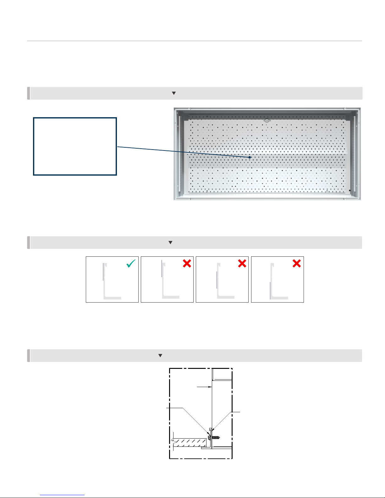
• If drywall perimeter is installed prior to the system, ensure that the opening is cut to the correct dimensions (as per the
submittal), and is square on all corners.
• Ensure all tools (as listed below) are on site and ready for use.
• A minimum of two (2) people will be required to install this system.
Required Tools/Parts
• To be supplied by contractor.
• (2+) 8 ft. ladders or scaffolding
• Laser level
• Cordless drill/impact
• #8 self-tapping screws (1/2 in. maximum length)
• Screwdriver bit(s) to suit self-tapping screws
• Allen keys (5/32 in. and 3/16 in.)
• Damp cloth(s) (for cleaning)
• Utility knife
• Chalk line
• Pliers with wire cutter
• Tape measure
• Clamps/locking plier
• Pre-stressed 12 gauge suspension wire (or approved alternative) with necessary equipment to hang wire
• Supplied by Price:
• Job specific submittal drawing showing all sizes and dimensions of module assembly sections
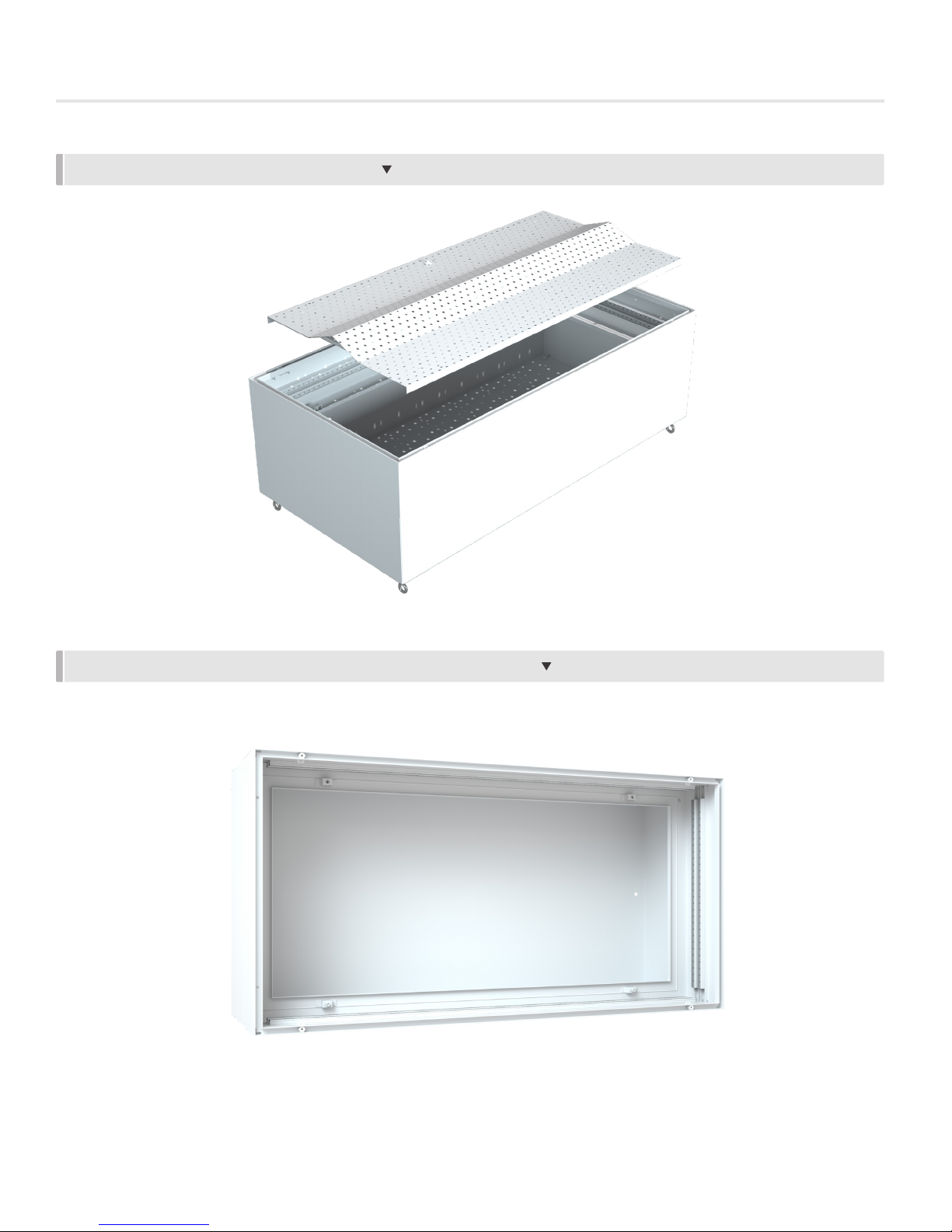
• Luminaire module sub-assembly sections (refer to job submittal drawing for quantity and sizes)
• Remote driver cabinets (refer to job specific submittal drawing for quantity, sizes and field wiring connection details)
• Dimmer switches (refer to job specific submittal drawing for quantity and field wiring connections)
• HGWC Perimeter ceiling sections (if applicable)
• 1/32 in. x 3/4 in. (t x w) white gasket tape – for between modules (Part Number 042373 004)
• The following supplied for bolting module assemblies together:
• Bolt
• Metal washer
• Lock nut assembly