PRICOM Design Layout Lighting Solution User manual

Layout Lighting Solution
User Manual

Layout Lighting Solution User Manual
Version 1.7
Copyright ©2014 PRICOM Design

Table Of Contents
Page 1
Layout Lighting Solution –User Manual
1Solution Overview...................................................................... 3
2Layout Lighting Main Board..................................................... 5
2.1 Power Input.......................................................................................................... 5
2.2 Power LED’s........................................................................................................ 5
2.3 Status LED’s ........................................................................................................ 6
2.4 Push Button.......................................................................................................... 6
2.5 Micro SD Card and Socket................................................................................... 6
2.6 Ethernet Jack ........................................................................................................ 6
2.7 PNET Jacks.......................................................................................................... 7
2.8 DCC Input............................................................................................................ 7
2.9 DMX Output ........................................................................................................ 7
2.10 Trigger Input..................................................................................................... 7
2.11 Control Output.................................................................................................. 7
2.12 Mode Switches ................................................................................................. 7
3Connections ............................................................................... 8
3.1 Power Input.......................................................................................................... 8
3.2 Ethernet Network Jack......................................................................................... 9
3.3 PNET Network Jacks........................................................................................... 9
3.4 DCC Input Terminal Strip.................................................................................. 10
3.5 DMX-512 Output Terminal Strip....................................................................... 11
3.6 Trigger Input Terminal Strip.............................................................................. 11
3.7 Control Output Terminal Strip........................................................................... 13
3.8 Mode Switches................................................................................................... 14
3.9 Mounting Holes.................................................................................................. 15
4Starter Kit Assembly................................................................ 16
4.1 Starter Kit Contents............................................................................................ 16
4.2 PNET DC Power Controller............................................................................... 17
4.3 PNET Opto-Input Module.................................................................................. 19
4.4 Optional LocoNet® Bridge Module .................................................................. 20
4.5 Power Connections............................................................................................. 20
4.6 Ethernet Connection........................................................................................... 21
4.7 Connecting PNET Cables................................................................................... 21
4.8 DIP Switch Settings ........................................................................................... 21

Table Of Contents
PRICOM Design
Page 2
5Software and Configuration .................................................... 23
5.1 Terminology....................................................................................................... 23
5.2 Finding the Layout Lighting Board.................................................................... 23
5.3 Launching a Browser ......................................................................................... 25
5.4 Creating Scenes.................................................................................................. 26
5.5 Assigning Dimmers............................................................................................ 27
5.6 Creating Presets.................................................................................................. 28
5.7 Creating Sequences............................................................................................ 32
5.8 Creating Sequence Steps.................................................................................... 33
5.9 Fast-Clock Triggers............................................................................................ 36
5.10 Next Steps....................................................................................................... 37
6Firmware Updates................................................................... 38
6.1 Updating Your Firmware................................................................................... 38
6.2 Downloading Firmware Updates ....................................................................... 38
6.3 How to Update Your Firmware.......................................................................... 38
7Problems & Support................................................................ 40
7.1 Help, I broke it!.................................................................................................. 40
7.2 E-mail................................................................................................................. 40
7.3 Web Site............................................................................................................. 40
Layout Lighting Solution –Overview
Page 3
Layout Lighting Solution –User Manual
1 Solution Overview
Congratulations!
Your PRICOM Layout Lighting Solution will bring you the next step to realism.
The Layout Lighting main board is the heart of a Lighting and Sound animation
sequencer solution and measures only 3 ½ by 4 ½ inches. This small board includes a
DMX-512 Dimmer Controller, complete PNET (PRICOM Network) host and slave
implementation, DCC Receiver, full web server, along with local trigger inputs and
control outputs, this is truly the most economical animation controller of its kind.
All configurations are stored on the included microSD Card, readily inserted into your
computer to backup any configurations. By using a microSD Card you are able to mount
the board to anything and anywhere, and easily update the firmware that the system uses.
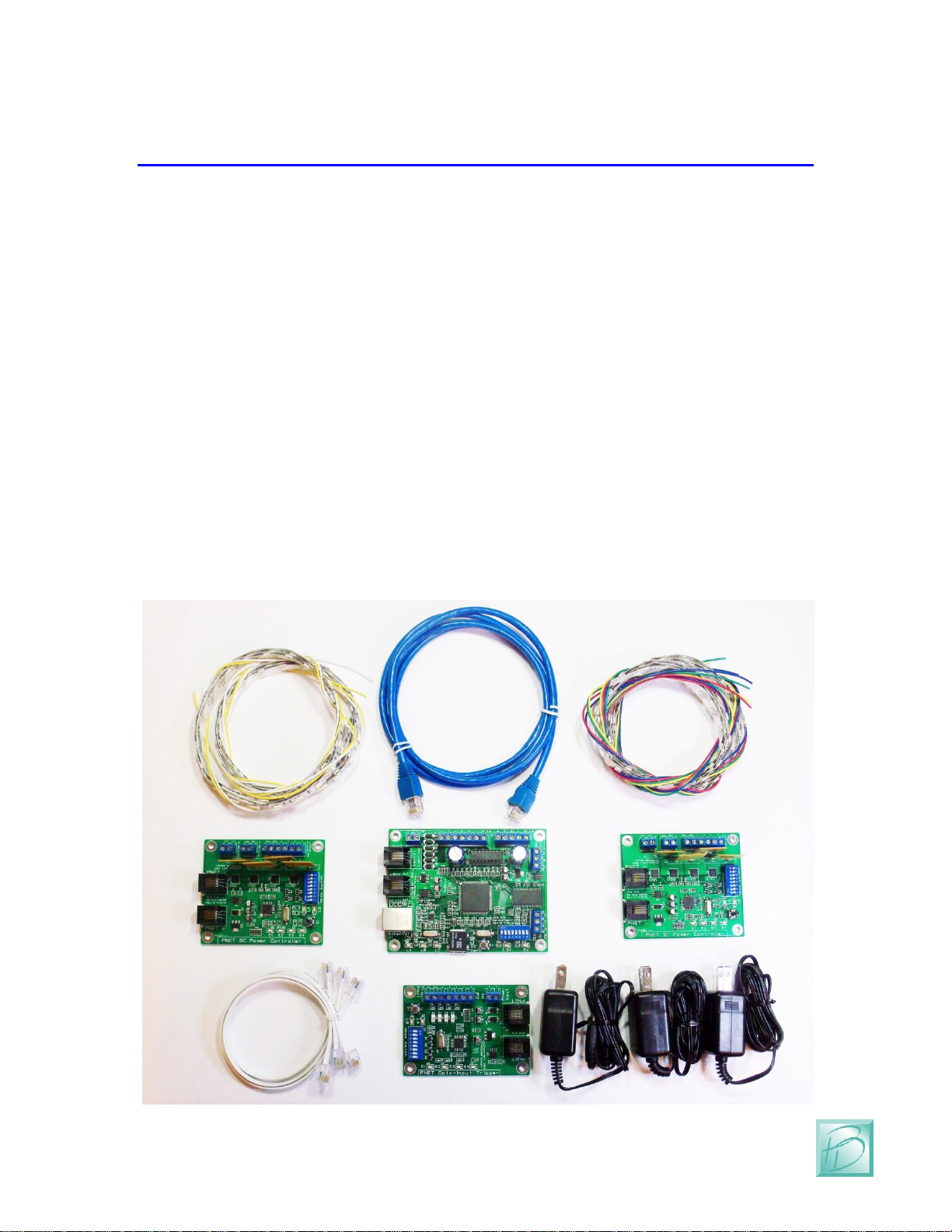
The PRICOM Layout Lighting Solution is available as a complete Starter Kit pictured
below. This represents a minimal configuration with One Layout Lighting Main Board,
Two PNET Power Controllers, One PNET Opto-Input Trigger board, Two RGB LED
Strips, and Two White LED Strips, 12VDC Power Supplies, and all necessary cables to
make it work right out of the box.

Layout Lighting Solution –Overview
PRICOM Design
Page 4
Of course you can expand your system indefinitely, depending on the size of your
application. DMX-512 equipment is available from many sources and priced quite
economically for DJ applications.
You can control external devices with our line of PNET control products. We have Small
current (PNET ULN-Output), large current (PNET DC Power Controller), and high
output quantity (PNET Hex Driver) products to meet your specific applications.
You can trigger events with our line of trigger boards. PNET Opto-Input gives you 4
Optically Isolated Input Triggers, and PNET Block Occupancy gives you 4 DCC Block
Detectors with small to large sensitivity. With these products you can control your
Layout Lighting via external devices such as a button, block occupancy, motion sensor,
etc.
We have even more PNET products in the planning stage now.
All configuration and control is performed over your local network using a web browser
such as Internet Explorer, Firefox, Chrome, Safari, or other browsers. You can use a
tablet, smart phone, or laptop for these functions, all it needs is a web browser.
In this manual, we will go over the features, configuration, and operation of not only the
Layout Lighting Solution, but also how to use many of the other PRICOM Design
products that work with the Layout Lighting Solution.
Layout Lighting Solution –Main Board
Page 5
Layout Lighting Solution –User Manual
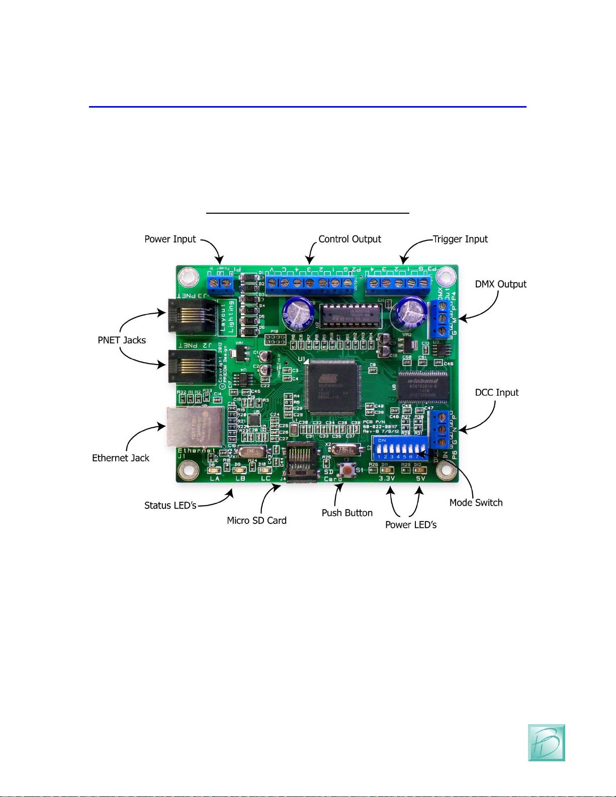
2 Layout Lighting Main Board
The following pages describe the features and functions of the Layout Lighting Main
Board. Later in the manual we will go into more detail about the connections, and the
software operations in a typical system. You can keep your solution simple, or make it as
elaborate as you wish. With so many options and Configurations available to you, the
possible uses are endless.
Figure 1 - Layout Lighting Main Board
2.1 Power Input
The Layout Lighting Main Board requires an external power source, which is applied to
this terminal strip. 9-18V AC or DC power can be used, but we strongly recommend
using 12VDC as this will be perfect for powering other PNET devices.
2.2 Power LED’s
One Green LED indicator for 3.3V and another for 5V. Both of these LED’s will be
illuminated anytime power is applied to the Power Input. If either of these LED’s is not
lit, the rest of the board will not operate correctly.

Layout Lighting Solution –Main Board
PRICOM Design
Page 6
2.3 Status LED’s
Three Status LED’s are included to show the current operations happening on the Layout
Lighting Main Board. LA is Blue, LB is Green, and LC is Red. Under normal operations,
LA will show PNET activity, LB will show Web Server activity, and LC will show SD
Card activity.
These LED’s have special meaning when performing Firmware Updates
(please see the section on Firmware Updates later in this manual)
2.4 Push Button
The push button is used to initiate Firmware Updates. If the button is pressed when the
power is applied, a new firmware image will be read from the SD card and written to the
FLASH memory of the Layout Lighting Main Board.
(Please see the section on Firmware Updates later in this manual)
2.5 Micro SD Card and Socket
All configuration and setup information is contained on this SD Card. You can use any
standard computer to backup your configuration data from this card. When a new
firmware update is desired, you simply copy the Firmware Image onto the SD card and
use the Push Button to trigger a Firmware Update.
The connector used on the Layout Lighting Main Board is unique in that the card is
loaded from the top and not from the front like some other connectors. One major
advantage of this style is that it ensures that the card does not accidently fall out when the
device is mounted.
To load the card into the connector, simply insert the card into the socket from the top
and while pushing down with your finger, pull towards yourself, you will feel when it is
secure. If the card is not properly fitted into the socket, it will actually pop back up, the
only time the card will remain down is when it is correctly inserted into the connector.
2.6 Ethernet Jack
The Layout Lighting Solution uses a computer or laptop with a web browser for all setup
and configuration. The Ethernet Jack must be connected to your home network in order
to be accessed by a web browser. The Ethernet connection is 10/100 Mbit Ethernet. At
power-up, the Ethernet Interface will request an IP address from your home router. You
must know the address given by your home router so that you can enter that IP address
into your web browser to reach the configuration pages.

Layout Lighting Solution –Main Board
Page 7
Layout Lighting Solution –User Manual
2.7 PNET Jacks
PNET (PRICOM Network) is the bus that allows many input and output modules to be
simply connected to your system. Both jacks are the same, and can be used
interchangeably. PNET uses standard 6-wire modular cabling, the same as most DCC cab
bus wiring.
2.8 DCC Input
Your Layout Lighting Solution can be directly attached to a DCC bus in order to use
DCC events as trigger sources. This input is not isolated, so it is important to connect the
DCC System Ground to the “G” terminal on this input.
(See the connections section later in this manual for more details)
2.9 DMX Output
A key feature of the Layout Lighting Solution is the ability to mix-and-match DC
dimmers connected to PNET, and AC dimmers connected to the industry standard DMX-
512 interface. The DMX output allows you to purchase any compliant devices and simply
attach them to the DMX-512 interface.
2.10 Trigger Input
The Trigger Input provides direct attachment of 4 local push-buttons. These can be used
for any function, but are perfect for master room light buttons. These inputs are not
isolated, and so are best used for push-buttons and not any other more elaborate input
triggers. For Optically Isolated Trigger Inputs, please consider our PNET Opto-Input
Trigger Board which contains 4 optically isolated input trigger channels.
2.11 Control Output
As its name implies, you may use this function on the Dream Player to control up to four
outputs such as LED’s, Relays, etc… The outputs can be controlled by Sequences
configured with your web browser.
2.12 Mode Switches
This DIP Switch can set master-control modes.
All positions are currently un-used and reserved for future use.

Layout Lighting Solution –Connections
PRICOM Design
Page 8
3 Connections
The following section provides detailed instructions for connecting your Layout Lighting
Solution. To get started quickly, all you need to do is connect the Power Input, the
Ethernet, and PNET to any attached boards. The Starter Kit Assembly section of this
manual describes setting up a basic first system. Then when you are ready, you can get
more advanced and use the Trigger Inputs and Control Outputs.
3.1 Power Input
The Layout Lighting Solution is provided with a 12VDC wall
transformer which matches the needs of any PNET boards
attached. With a 12VDC input, the Main Board will draw
about 250MA when active. You can use any suitable power
supply of 9-18V AC or DC, but we strongly recommend
using 12VDC as this will be perfect for powering other PNET
devices.
If you wish to power multiple PNET boards, a single larger
power supply can be used, just allow for 250MA for the
Layout Lighting Main Board. As a convenience to you, we
offer a full range of Power Supplies ranging from 12VDC @
1Amp up to 12VDC @ 30Amp. Please visit our web site
www.pricom.com
The power source used can be shared with other devices, but
be careful as some of the PNET devices are polarity sensitive.
The PNET Power Controller is a perfect example. Putting the
Layout Lighting Main Board on its own 12VDC @ 2A power
supply is usually sufficient and keeps the high-current supply
separated and prevents accidental polarity issues.
To connect the power supply to the Layout Lighting Main
Board, locate the 2-position “Power Input” terminal strip.
If your desired power-supply comes with a connector on the
end, simply clip it off as shown to the right. Separate the two
wires and strip some insulation off to expose the actual wires
then twist them to keep the strands together. Secure the
stripped wire ends to the 2 terminals of the Power Input
terminal strip. The polarity of an AC or DC power source is
not important as there is a bridge rectifier included on the
Layout Lighting Main Board.

Layout Lighting Solution –Connections
Page 9
Layout Lighting Solution –User Manual
3.2 Ethernet Network Jack
Your Layout Lighting Solution leverages the best of Web Technology and utilizes HTML
and java for all setup and configuration functions via a Laptop, Tablet, or Smart Phone.
In order to achieve connectivity, you need to connect your Layout Lighting Main Board
to an Ethernet Network. The Ethernet Interface will automatically negotiate 10Mbit or
100Mbit connection depending on your network router.
Figure 2 - Ethernet Network Jack
The Layout Lighting Main Board will automatically request an “IP Address” (Internet
Protocol Address). This is the address that enables your PC/Laptop/Tablet to talk to the
Layout Lighting Board. In order to automatically request this IP address, we utilize
DHCP (dynamic host configuration protocol). If your home network does not support
an alternate approach.
Even with DHCP, it is necessary for you to determine exactly what IP address was given
by your home network. If you know how to login to your home gateway, you can look at
the connected hosts list, and look for a MAC address that matches the sticker on the
bottom of your Layout Lighting Main Board (1C:97:3D:00:xx:xx). Once you know the IP
address given to your Layout Lighting Main Board, we suggest setting up a “reservation”
so that it will always receive the same IP address.
We are working on a better solution to this IP address situation, please check our web site
for software updates for this and all of our products.
3.3 PNET Network Jacks
The Layout Lighting Main Board includes TWO PNET Jacks for convenient connection
of many PNET devices. Both jacks are the same, giving you the flexibility to ‘loop’
through and connect many devices to the PNET network.

Layout Lighting Solution –Connections
PRICOM Design
Page 10
The cables are 6-wire Modular cables and can be flat or twisted pairs. PNET cables
include 12VDC power that comes in very handy for the PNET Control Output as the
12VDC on the cable can power many of the smaller PNET boards.
PNET Cables should be wired as “Straight Through” and not “flip” anywhere along the
path. Nothing will be damaged if a cable is reversed, but the PNET Communications
Data lines would be reversed making PNET malfunction. PNET cables can be plugged or
un-plugged with the power on.
Figure 3- PNET Jack Pinout
Pin
Name
Description
1
+12VDC
PNET Power Supply
2
GND
PNET Signal Ground
3
PNET
Communications Data
4
PNET
Communications Data
5
GND
PNET Signal Ground
6
+12VDC
PNET Power Supply
ATTENTION:
The PNET Bus Requires Termination!
We have included a terminator with your kit. There needs to be at
least ONE terminator in order for PNET to function. Ideally, there
should be a terminator at each end of your PNET Bus.
To create your own terminators, simply put a single 120 Ohm resistor between the
PNET Communications Data pins 3 & 4.
Place one of these termination resistors at each end of the PNET bus.
3.4 DCC Input Terminal Strip
Another key feature of the Layout Lighting Solution is the ability to trigger events from
DCC mobile or accessory commands. To facilitate this connection, we provided a DCC
Input Interface. This input is NOT isolated, so it is important to keep the Ground of all
systems the same. The DCC System Ground should be attached to the “G” terminal of P6
in order to reduce the chance of noise and grounding issues. Since DCC is not polarity
sensitive, the “N” and “P” terminals can be reversed, but the Negative and Positive
terminals are as follows:

Layout Lighting Solution –Connections
Page 11
Layout Lighting Solution –User Manual
Figure 4 –DCC Input Terminal Strip (P6)
Terminal
Name
Description
1
“G”
System Ground
2
“N”
DCC Signal -
3
“P”
DCC Signal +
3.5 DMX-512 Output Terminal Strip
A tremendous amount of expansion is possible using DMX-512 which is a professional
standard for Digital Control of AC Dimmers. We have leveraged the popularity of this
standard to your advantage. Many products for the DJ industry are available including
Dimmer Packs, LED “PAR” Cans, etc. The Professional Connector is a 5-pin XLR style
connector.
Figure 5 - DMX Output Terminal Strip (P4)
Terminal
Name
Description
1
“G”
DMX Shield/Ground
2
“M”
DMX Signal -
3
“P”
DMX Signal +
In the Semi-Professional market, a 3-pin XLR style connector has been made universally
standard. This makes the cables to connect DMX-512 signals a simple XLR microphone
cable. Microphone cables are easy to find and easy to obtain the connectors for. With this
in mind, we made our DMX-512 connections using a 3-position terminal strip, matching
the pinout for the 3-pin XLR connector.
Figure 6 - DMX 3-Pin XLR Connector Wiring
Terminal
Name
Description
1
“G”
DMX Shield/Ground
2
“M”
DMX Signal -
3
“P”
DMX Signal +
3.6 Trigger Input Terminal Strip
Local push-buttons can be wired to the Layout Lighting Solution enabling direct
connection of external event sources. A typical application for this would be a master
control push button panel. This section describes the electrical connections for the
Trigger Inputs. To program the trigger inputs to cause actions within sequences and steps,
see the section on Programming.
Layout Lighting Solution –Connections
PRICOM Design
Page 12
The Trigger Inputs of the Layout Lighting Solution are NOT optically isolated which
means you need to be careful about sharing ground pins with external sources.
As a convenience to your wiring, you simply need to connect buttons between the
appropriate trigger input and the ground terminal.
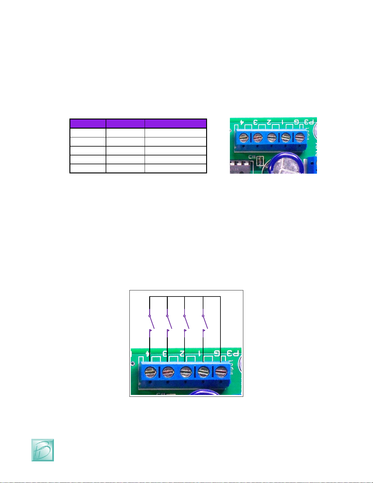
Figure 7 –Trigger Input Terminal Strip (P3)
Terminal
Name
Description
1
GND
Trigger Ground
2
Trigger-1
Trigger #1 Input
3
Trigger-2
Trigger #2 Input
4
Trigger-3
Trigger #3 Input
5
Trigger-4
Trigger #4 Input
The trigger input terminals (Trigger-1 to Trigger-4) provide connection to the trigger
inputs. Terminal #1 (GND) is connected to the local ground for all 4 trigger inputs. Since
these inputs are intended for Push Buttons, there is no need for power, and we have
provided the appropriate pull-up resistors on the board.
The following example shows how to connect switches (or relays for that matter) directly
to the Layout Lighting Main Board. Each Trigger Input can then be individually
connected to the GND pin though any suitable switching device such as a push-button or
relay.
Figure 8 - Simple Trigger Input Button Connections
Layout Lighting Solution –Connections
Page 13
Layout Lighting Solution –User Manual
3.7 Control Output Terminal Strip
The Layout Lighting Solution is capable of controlling many types of devices and loads
connected to the Control Outputs. This section describes the electrical connections for the
Control Outputs.
The Control Outputs of the Layout Lighting Main Board are not isolated in any way from
the Ground of the system. If grounding problems become an issue for your application,
an external relay can be used to isolate the load from the Layout Lighting Solution.
As a convenience to your wiring, you may use the power supplied on the Control Output
Terminal Strip, but doing so will draw power from the internal 5V regulated supply used
to power the Layout Lighting Main Board. Use this convenience power for LED’s, or
small relays. If you intend to power any larger loads, please consider an external power
source for the Control Outputs.
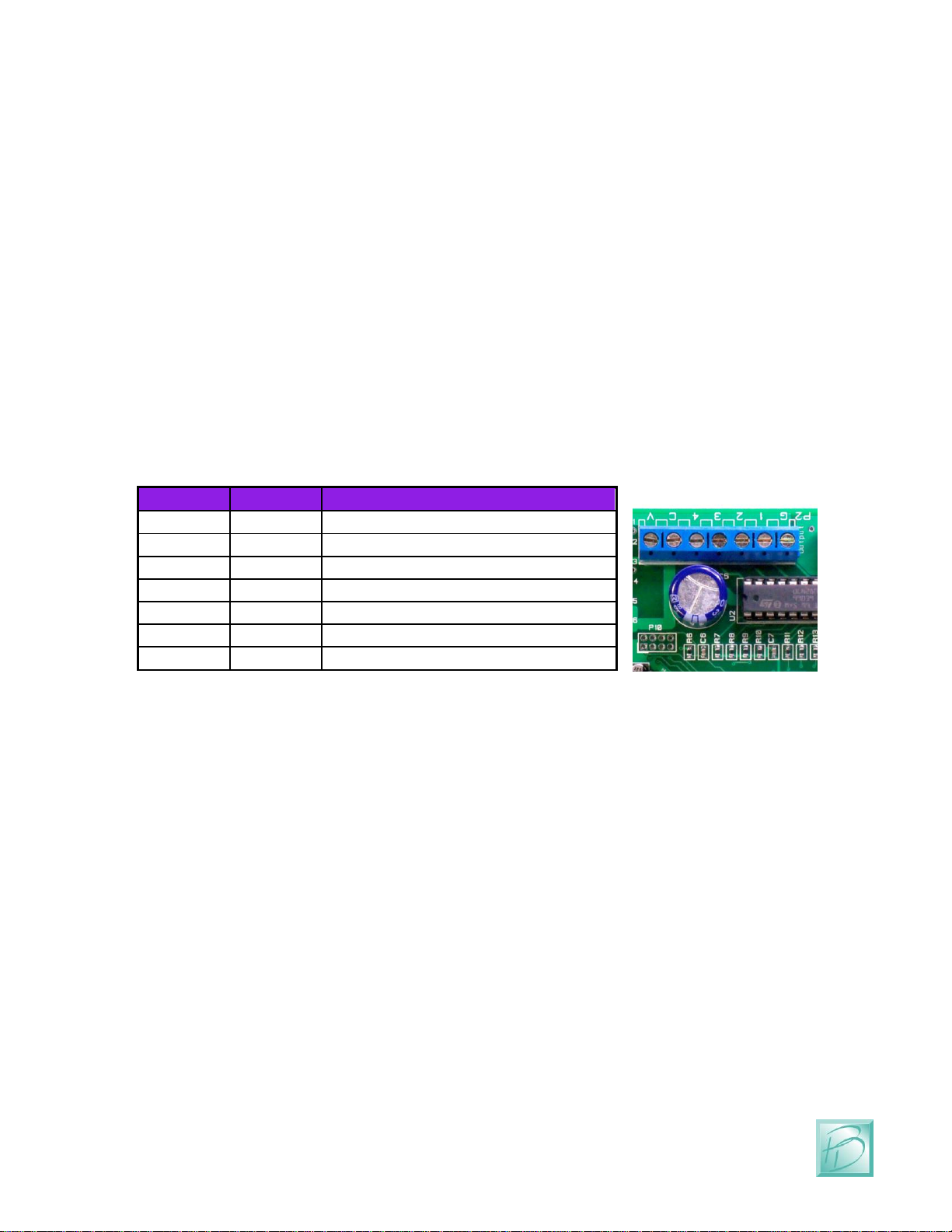
Figure 9 –Control Output Terminal Strip Pinout (P2)
Terminal
Name
Description
1
GND
Convenience power supply ground
2
Output-1
Control Output #1
3
Output-2
Control Output #2
4
Output-3
Control Output #3
5
Output-4
Control Output #4
6
Clamp
Common Clamp Diode Connection
7
5V
Convenience power supply (5VDC)
The control output terminals (Output-1 to Output-4) provide connection to a Darlington
Transistor Array (Collector) used to Sink Power, but cannot Supply Power. Each Output
is capable of sinking 400MA using the ULN2803 in the socket at U2. The Darlington
Array has its Emitters connected to the GND Terminal #1. External or Convenience
power can be used to power the load, but the reference and current ground will be using
GND Terminal #1.
Terminal #6 (Clamp) is connected to the Darlington Array protection diodes (Cathode)
for all 4 outputs. If you are driving an inductive load such as a relay, the Clamp terminal
should be connected to the power source being used for the load. This Clamp Terminal
will prevent the back-lash of the relay from destroying the Darlington Array. If you are
simply driving LED’s this terminal can be left un-connected.
Terminal #7 provides a local power source that is not isolated from the Layout Lighting
Main Board, but can be used to simplify wiring if just powering LED’s or other small
loads. Power used from this terminal can cause the on-board voltage regulator to become
hot under load.
Layout Lighting Solution –Connections
PRICOM Design
Page 14
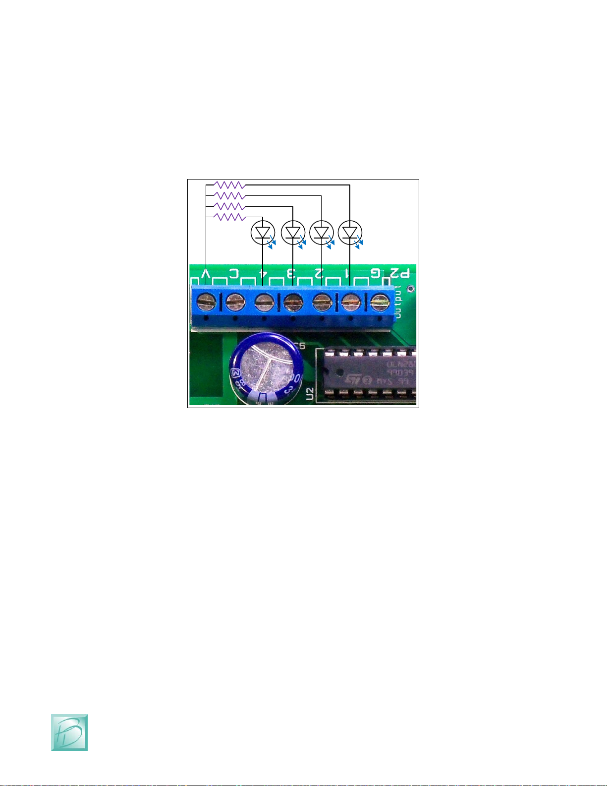
The following example shows a simple way to connect status LED’s to the Layout
Lighting Solution using the convenience 5VDC power supply. The LED’s will require
current-limiting resistors since each Control Output can sink 400MA and would burn-out
the LED’s. Since the LED’s do not present an inductive load, the Clamp terminal has
been left un-connected.
Figure 10 - Simple Control Output LED Connections
220Ω
The Control Outputs can also be used to drive conventional DC powered lamps or DC
powered relays. However, if you need to control larger DC loads, please consider the
PNET DC Power Controller as a High-Current 4-channel controller conveniently
connected to PNET. At 8Amps per channel, you can control some serious loads!
3.8 Mode Switches
The Layout Lighting Solution has many options available through programming using
the web interface. We placed a DIP Switch to set modes, but have not implemented any
use for them yet.

Layout Lighting Solution –Connections
Page 15
Layout Lighting Solution –User Manual
Figure 11 - Mode Switch Settings
(All Switches are unused and reserved for Future Use)
3.9 Mounting Holes
The Layout Lighting Main Board can be mounted to any non-conducting surface using
the supplied mounting holes. We suggest using a .25” or .375” nylon stand-off to keep
airflow around the board. Our favorite screw to use is #6 x 1” or #6 x .75” depending on
the length of your standoffs. The mounting holes are electrically isolated, and using steel
screws is fine, but please be careful not to over tighten them.
Layout Lighting Solution –Starter Kit Assembly
PRICOM Design
Page 16
4 Starter Kit Assembly
Previously in this document, we have described the Layout Lighting Main Board features
and its connections. This section will introduces you to the rest of the components
included in the Layout Lighting Solution Starter Kit. This section will cover all the basic
connections and operations, even if you purchased individual parts not the Starter Kit.
Additional data for each module is included in their respective Quick Start Guides. Please
refer to the individual quick-start manuals in addition to this guide. This manual
combined with our web site videos should get you up and running in the fastest possible
manner.
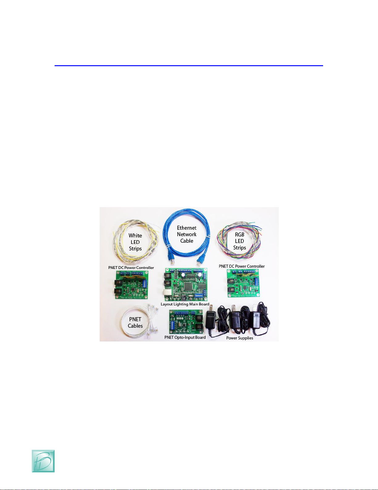
4.1 Starter Kit Contents
Whether you purchased a Starter Kit, or selected the exact components you need, you
will end up with items similar to those pictured below:
Figure 12- Layout Lighting Starter Kit Contents
Essentially, you will need a Layout Lighting Solution Main Board, Power Supplies,
Ethernet Cable, PNET Cables, and some number of PNET DC Power Controllers.
It is possible to operate the Layout Lighting Solution with only DMX-512 dimmers and
no PNET dimmers at all. LED lighting provides such an economical alternative to other
light sources that we have included 2 sets of Red, Green, Blue (RGB) and White LED
strips in the Starter Kit. We have included 2 one meter lengths of RGB, and 2 one meter
lengths of White LEDs. The combination of RGB & White strips allows infinite color
mixing and flexibility.

Layout Lighting Solution –Starter Kit Assembly
Page 17
Layout Lighting Solution –User Manual
The power supplies included in the Starter Kit are enough to power the Layout Lighting
Main Board as well as separate 12VDC Power Supplies for each of the PNET DC Power
Controller Boards. Each LED strip draws about 1Amp at 12VDC, so each PNET DC
Power will require about 2A at 12VDC. If you are connecting more than 2 Metres of
LED strip to a PNET DC Power Controller, you will need a larger Power Supply.
4.2 PNET DC Power Controller
The PNET DC Power Controller is a key element in the control of low-voltage DC lights,
including LED strips. The DC Power Controller can supply up to 8Amps @ 12VDC on
each of the 4 outputs. That adds up to a total of 32Amps @ 12VDC maximum capacity
for each PNET DC Power Controller. With that kind of power, care must be used to
ensure wiring is correct, especially the High Current DC Power Input Polarity.
Figure 13 - PNET DC Power Controller
Looking at the picture above, please note the High Current Input Terminal Strip. To the
left are 2 terminals BOTH labeled GND. This provides the easy ability to ‘chain’
multiple DC Power Controllers onto a shared 12VDC power Bus.
Similarly, the High Current Input PWR terminals are connected together to allow easy
‘chain’ ability onto a shared 12VDC power Bus.

Layout Lighting Solution –Starter Kit Assembly
PRICOM Design
Page 18
The Control Output Terminal Strip is used to connect to the Starter Kit LED strips. Our
strips are pre-wired with Yellow Wires on the 12VDC connections, and the matching
color on the ‘sink’ side of each LED color. Red=Red, Green=Green, Blue=Blue,
White=White.
Figure 14 - PNET DC Power Controller Connections
Terminal
Name
Description
RGB Strip
White Strip
1
Output-1
Dimmer Output #1
Red Wire
2
Output-2
Dimmer Output #2
Green Wire
3
Output-3
Dimmer Output #3
Blue Wire
4
Output-4
Dimmer Output #4
White Wire
5
PWR
Power supply output
(12VDC)
Yellow Wire
6
PWR
Power supply output
(12VDC)
Yellow Wire
Figure 15 - PNET DC Power Controller Wiring
As you can see in the table and pictures above, we have assigned PNET DC Dimmer #1
to Red, #2 to Green, #3 to Blue, and Dimmer #4 to White. This matches the standard
order of R,G,B,W. The two small Yellow wires receive the +12VDC from the High
Current Input bus wire (Large Yellow) connected to terminal strip position ‘PWR’ and
makes the wiring to a large 12VDC bus quite convenient. As you can also see from the
picture above, we used Black as our GND and Yellow as our 12VDC Power Bus. Notice
the Black coming in and going out to the next board are NEXT TO EACH OTHER.
Similarly, the Yellow 12VDC Power Bus wires enter and exit this module NEXT TO
EACH OTHER.
Table of contents
Popular Lighting Equipment manuals by other brands


LIGMAN
LIGMAN AUSTIN 1 installation manual

Loop-Loc
Loop-Loc Super Dense Mesh installation guide

Johnson Outdoors
Johnson Outdoors Scubapro Nova 1000R manual

WULF
WULF MONOLUX manual

Intermatic
Intermatic RC4G Installation & operating instructions

Ecoxotic
Ecoxotic Cannon PRO LED Pendant MANUAL & SAFETY INSTRUCTIONS


