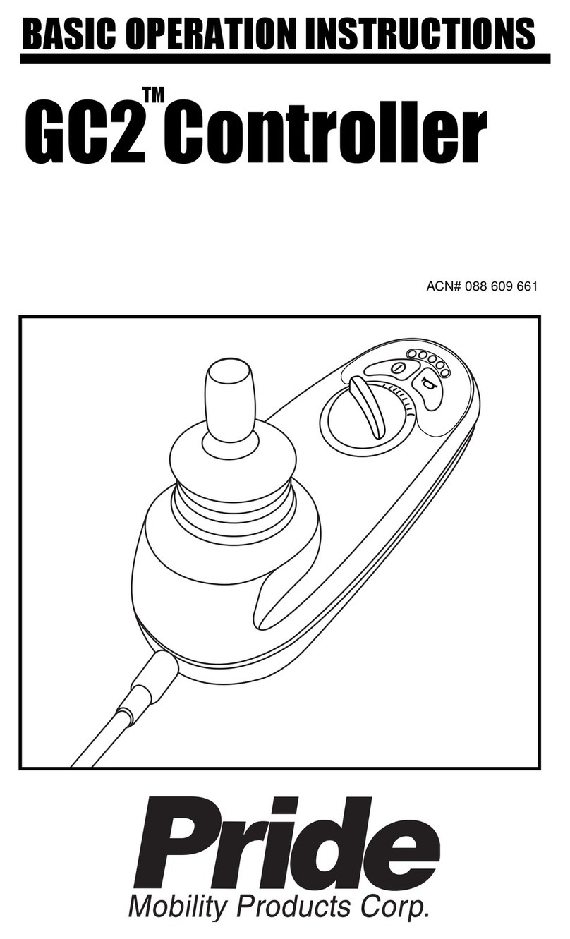
Pride Dynamic Controller INFMANU3676 User manual

ACN# 088 609 661
Synergy TRU-Balance
Po
BASIC OPERATION INSTRUCTIONS
Dynamic
Controller
ACN# 088 609 661

2 BasicOperationInstructions
Dynamic Controller www.pridemobility.com
SAFETY GUIDELINES
Copyright© 2008
PrideMobilityProductsCorporation
INFMANU3676/RevB/May 2008
WARNING! An authorized Pride Provider or a qualified
technician must perform the initial setup of this product and
must perform all of the instructions in this manual.
Thesymbolsbelowareusedthroughoutthisowner'smanualandonthecontroller
toidentifywarningsandimportantinformation.Itisveryimportantforyoutoread
themandunderstandthem completely.
WARNING! Indicates a potentially hazardous condition/
situation. Failure to follow designated procedures can cause
either personal injury, component damage, or malfunction.
On the product, this icon is represented as a black symbol
on a yellow triangle with a black border.
MANDATORY! These actions should be performed as
specified. Failure to perform mandatory actions can cause
personal injury and/or equipment damage. On the product,
this icon is represented as a white symbol on a blue dot with
a white border.
PROHIBITED! These actions are prohibited. These actions
should not be performed at any time or in any circumstances.
Performing a prohibited action can cause personal injury
and/or equipment damage. On the product, this icon is
represented as a black symbol with a red circle and a red
slash.
NOTE: These instructions are compiled from the latest specifications
and product information available at the time of publication. We re-
serve the right to make changes as they become necessary. Any changes
to our products may cause slight variations between the illustrations
and explanations in this manual and the product you have purchased.
The latest/current version of this manual is available on our website.
088 609 661

BasicOperationInstructions 3
www.pridemobility.com Dynamic Controller
TABLE OF CONTENTS
LABEL INFORMATION .................................................................... 4
INTRODUCTION................................................................................. 5
DYNAMIC CONTROLLER ............................................................... 7
PRECAUTIONARY GUIDELINES................................................. 7
OPERATING THE DYNAMIC CONTROLLER ........................11
CONTROLLER CONNECTOR...................................................... 16
OFF-BOARD CHARGER/PROGRAMMING SOCKET ............. 16
LOCK MODE....................................................................................... 16
ACTUATOR ADJUSTMENT ......................................................... 17
SLEEP MODE (IF ENABLED) ..................................................... 18
OUT OF NEUTRAL AT POWER UP (OONAPU)................... 18
ERROR CODES ................................................................................. 18
CARE AND MAINTENANCE ........................................................ 19
WARRANTY ........................................................................................ 19

4 BasicOperationInstructions
Dynamic Controller www.pridemobility.com
Read and follow the information in the owner’s manual.
Avoid exposure to rain, snow, ice, salt, or standing water
whenever possible. Maintain and store in a clean and dry
condition.
EMI-RFI - This product has been tested and passed at an
immunity level of 20 V/m.
Disposal and recycling - Contact your authorized Pride
Provider for information on proper disposal and recycling of
your Pride product and its packaging.
PRODUCTSAFETYSYMBOLS
Thesymbols beloware usedon thecontroller toidentify warnings,mandatory
actions, and prohibited actions. It is very important for you to read and under-
standthemcompletely.
LABEL INFORMATION

BasicOperationInstructions 5
www.pridemobility.com Dynamic Controller
INTRODUCTION
WELCOMEto PrideMobility ProductsCorporation (Pride).The productyou
havepurchasedcombinesstate-of-the-artcomponentswith safety,comfort, and
stylinginmind.Weareconfidentthatthedesignfeatureswillprovideyouwiththe
conveniencesyouexpectduringyourdailyactivities.Understandinghowtosafely
operateandcarefor this productshouldbringyouyearsoftroublefreeoperations
andservice.
Readand followall instructions, warnings, and notes in this manual beforeat-
temptingtooperateyourproductforthefirsttime.Youmustalso read all instruc-
tions,warnings,andnotescontainedinanysupplementalinstructionalbookletsfor
thecontroller,frontriggings,and/orseatingsystemthataccompaniedyour power
chair before initial operation.Your safetydepends upon you, as well as your
provider,caretaker,orhealthcareprofessionalinusinggoodjudgement.
Thismanualistobeusedinadditiontothepowerbaseowner’smanualthatcamewith
yourpowerchair.Ifthereisanyinformationinthismanualwhichyoudonotunderstand,
or if you require additional assistance for setup or operation, please contact your
authorizedPrideProvider.Failuretofollowtheinstructions,warnings,andnotes
inthismanualandthoselocatedonyourPrideproductcanresultinpersonal
injuryand/orproductdamageandwillvoidPride’sproductwarranty.
PURCHASER’SAGREEMENT
Byacceptingdeliveryof this product, youpromisethatyouwillnotchange,alter,
or modify this product or remove or render inoperable or unsafe any guards,
shields,orothersafetyfeaturesofthisproduct;fail,refuse,orneglecttoinstallany
retrofitkits fromtimeto timeprovided byPrideto enhanceor preserve thesafe
useofthis product.
INFORMATIONEXCHANGE
We wanttohear yourquestions,comments, and suggestionsabout this manual.
We would also like to hear about the safety and reliability of your new Pride
product,andabouttheserviceyoureceivedfromyourauthorizedPrideProvider.
Pleasenotifyusofanychangeofaddress,sowecankeepyouapprisedofimportant
informationabout safety, newproducts,and newoptionsthat canincreaseyour
abilitytouse andenjoyyourPride product.

6 BasicOperationInstructions
Dynamic Controller www.pridemobility.com
NOTE: If you ever lose or misplace your product registration card or your
copy of this manual, contact us and we will be glad to send you a new one
immediately.
My authorized Pride Provider Is:
Name: _____________________________________________________
Address:____________________________________________________
PhoneNumber: ______________________________________________
PurchaseDate: _______________________________________________

BasicOperationInstructions 7
www.pridemobility.com Dynamic Controller
DYNAMICCONTROLLER
TheDynamiccontrollerisamodularelectroniccontrollersystemthatallowsyouto
operateyourpowerchair. Itisdesignedtoallowtheusertohavecompletecontrol
overchairmovement and speed.
Thecontroller isavailable inboth 50-ampand 60-ampconfigurations, and has
beenpre-programmed to meet a typical user’s needs.The program is setusing
eitherapersonalcomputerwithsoftwareprovidedbythecontrollermanufacturer
orwithahand-heldprogrammer,alsoprovidedbythecontrollermanufacturer.
WARNING! The controller program can affect speed,
acceleration, deceleration, dynamic stability, and braking.
If it is programmed incorrectly or outside of the safe limits
as determined by your healthcare professional, it can create
a dangerous situation. Only the power chair manufacturer,
an authorized representative of the manufacturer, or a trained
service technician should program the controller.
PRECAUTIONARYGUIDELINES
BeforeoperatingtheDynamiccontroller,pleasereadthefollowing.Theseguidelines
areprovidedforyourbenefitandwillaidyouinthesafeoperationofthecontroller
system.
!Turn offthepower to thecontrollerwhentransferringto or fromyourpower
chair.
!Followalloftheproceduresandheedthewarningsasexplainedinyourpower
chairowner’smanual.

8 BasicOperationInstructions
Dynamic Controller www.pridemobility.com
Electromagnetic and Radio Frequency Interference (EMI/RFI)
WARNING! Laboratory tests have shown that electromagnetic
and radio frequency waves can have an adverse affect on
the performance of electrically-powered mobility vehicles.
ElectromagneticandRadioFrequencyInterferencecancomefromsourcessuchas
cellularphones,mobiletwo-wayradios(suchaswalkie-talkies),radiostations,TV
stations,amateurradio(HAM)transmitters,wirelesscomputerlinks,microwavesig-
nals,pagingtransmitters,andmedium-rangemobiletransceiversusedbyemergency
vehicles.Insomecases,thesewavescancauseunintendedmovementordamageto
thecontrolsystem.Everyelectrically-poweredmobilityvehiclehasanimmunity(or
resistance)toEMI.Thehighertheimmunitylevel,thegreatertheprotectionagainst
EMI.Thisproducthasbeentestedandhaspassedatanimmunitylevelof20V/m.
WARNING! Be aware that cell phones, two-way radios,
laptops, and other types of radio transmitters may cause
unintended movement of your electrically-powered mobility
vehicle due to EMI. Exercise caution when using any of these
items while operating your mobility vehicle and avoid coming
into close proximity of radio and TV stations.
WARNING! The addition of accessories or components to
the electrically-powered mobility vehicle can increase the
susceptibility of the vehicle to EMI. Do not modify your power
chair in any way not authorized by Pride.
WARNING! The electrically-powered mobility vehicle itself
can disturb the performance of other electrical devices
located nearby, such as alarm systems.
NOTE: For further information on EMI/RFI, go to the Resource Center on
www.pridemobility.com. If unintended motion or brake release occurs, turn
your controller off as soonas it issafe to do so. ContactPride or your autho-
rized Pride Provider to report the incident.

BasicOperationInstructions 9
www.pridemobility.com Dynamic Controller
Dynamic Controller Features
Figure 1 provides information on the Dynamic controller components and
connections.Usethisdiagramtofamiliarizeyourselfwiththefunctionandlocation
ofeachcomponentbeforeusingtheDynamiccontroller.
ThefollowingfunctionsareavailablewiththeDynamiccontroller:
!JoystickControl
Thejoystick is usedto controlthedirection andspeed of thepower chair.
!SpeedAdjustment
Theuser can increaseor decrease themaximum speed ofthe power chair.
!ActuatorAdjustment
Theuser cancontrol positioningof powerseat actuators with the Dynamic
controller.
!SleepMode
Thisfeatureisdesignedtopreservebatterychargeandcanbedisabledthrough
programming.
!Out of Neutral at Power Up (OONAPU)
Asafety featuredesigned toprevent thepower chairfrom overheatingand
causingdamagetothe motors orcontroller.

10 BasicOperationInstructions
Dynamic Controller www.pridemobility.com
Figure 1. Dynamic Controller Components and Connections
Horn Key
Activates a warning horn.
Joystick
A multi-functional tool used
to control speed and direction.
Speed Setting
Indicator
Series of five colored LEDs
which display the speed
setting.
Battery Condition Meter
Indicates the approximate amount of
battery life using color-coded LEDs.
Off-board Charger/
Programming Socket
Connects to battery
charger plug or
programmer.
On/Off Key
Press to power on or
off the power chair and
controller.
Service Indicator
Displays error codes.
Attendant Control
Indicator
Indicates when the optional
Attendant Control Unit is
activated.
Speed Decrease Key
Used to decrease the
speed setting.
Speed Increase Key
Used to increase the
speed setting.

BasicOperationInstructions 11
www.pridemobility.com Dynamic Controller
Figure 2. Dynamic Controller
OPERATING THEDYNAMIC CONTROLLER
The Dynamic controller is used to operate your power chair and all of its
components.
TheDynamiccontrollerconsists of(seefigure2):
1. joystick
2. keypad
3. off-boardcharger/programmingsocket
4. controllerconnector
5. powermodule
Joystick Control
Thejoystickcontrolsthedirectionandspeedofyourpowerchair.Whenyoumove
thejoystickfromtheneutral(center)position,theelectromagneticbrakesrelease
andallow yourpower chairto move. The farther youpush thejoystick fromits
neutralposition,thefasteryourpowerchairmoves.Whenyoureleasethejoystick
andallowittoreturntotheneutralposition,youengagetheelectromagneticbrakes.
Thiscausesyourpowerchairto decelerate and cometoacompletestop.
2
3
4
5
1

12 BasicOperationInstructions
Dynamic Controller www.pridemobility.com
Figure 3. Dynamic Controller 4-key Keypad
Figure 4. Dynamic Controller 7-key Keypad

BasicOperationInstructions 13
www.pridemobility.com Dynamic Controller
Figure 5. Dynamic Controller 8-key Keypad
Figure 6. Dynamic Controller 9-key Keypad

14 BasicOperationInstructions
Dynamic Controller www.pridemobility.com
Keypad
Thekeypadislocateddirectlyinfrontofthejoystick.Itcontainskeysthatyouwill
useto control yourpower chair. See figure2.
On/Off Key
Theon/offkeyturns the systemonandoff.
WARNING! Unless faced with an emergency situation, do
not use the on/off key to stop the chair. This will cause the
power chair to stop abruptly.
WARNING! Always turn the power off when you are stationary
to prevent unexpected movement.
NOTE: If the joystick is not in the neutral (center) position when you turn
on the power, you may cause a fault in the system. See “Out Of Neutral At
Power Up (OONAPU).”
Horn Key
Thehornkeyactivatesawarning horn.
Battery Condition Meter
Thebatteryconditionmeter consists ofeightlightsarrangedinanarcovertheon/
offkey.As thebattery voltagedrops, the numberof lightsreduces from rightto
left.Whenthe batterycapacitydropsto10%orbelow,theleftredLEDwillflash.
!LeftRedLED Flashing:The batterycharge is low;charge thebatteriesas
soonas possible.
!Right-to-LeftRippleofLEDs:Thecontroller is inlock mode;unlock the
controller.
!Left-to-Right Ripple of LEDs Alternating with Steady Display: The
controllerisinprogramming,inhibit,orchargingmode.Whenthejoystickis
moved,thespeedgaugewillalsoflash.

BasicOperationInstructions 15
www.pridemobility.com Dynamic Controller
Speed Keys
There are two keys that control the speed. Press the speed increase key to in-
creasethe speed. Pressthe speed decreasekey todecreasethe speed.Thespeed
settingis displayedon thespeed settingindicator. Ifyour power chair was pro-
grammedwith adrive profile,contact your authorizedPride Providerfor more
information.
NOTE: We recommend that the first few times you operate your power
chair, you set the speed to the slowest setting until you become familiar
with your new power chair.
Speed Setting Indicator
Thespeed setting indicatorindicatesthe currentspeedof your powerchair.The
speedsettingindicator consistsof16 lights arrangedclockwise around thehorn
key.As the speed of the power chair increases, the number of lights increases.
There are five larger LEDs which represent 0%, 20%, 40%, 60%, 80%, and
100% of the power chair’s maximum speed. Press the speed decrease key or
speedincrease keyonce toadjust thespeed in the five larger increments. Press
andhold thethespeed decreasekey or speedincrease keyto adjust thespeed in
individualincrements.
NOTE: When the bottom, left-most green LED is flashing, it indicates
that the controller is in speed limit mode.
Service Indicator
Theservice indicatordisplays Dynamiccontroller errorcodes. Referto “Error
Codes.”
Attendant Control Indicator (For Optional Equipment)
Theattendantcontrolindicatorisonwhen the optionalAttendant Control Unitis
activated.
Actuator Select Key with Lights (For Optional Equipment)
Ifyour powerchair isequipped withpower accessories suchas apower seator
power elevating leg rests, you can operate them through the keypad. Refer to
“ActuatorAdjustment.”

16 BasicOperationInstructions
Dynamic Controller www.pridemobility.com
Right/Left Turn Indicator Keys (For Optional Equipment)
Theright/leftturnindicatorkeystoggleeithertheleftorrightturnindicators.Press
oncetoturn on andpressagain to turnoff.You canalsoturnofftheselected turn
indicatorbypressing theoppositeindicator key orthehazard key.
Light Key (For Optional Equipment)
Thelightkeyturnstheheadlights/taillightsonandoffindependentofotherindicators.
Hazard Key (For Optional Equipment)
The hazard key activates both turn indicators at the same time.You can only
cancelthisbypressingthehazard key again.
CONTROLLERCONNECTOR
ThisconnectstheDynamiccontroller to thepowermodulelocatedonthepower
base.
OFF-BOARDCHARGER/PROGRAMMINGSOCKET
You may use an off-boardchargerto chargethepowerchairbatteriesthroughthe
3-pin socket located on the front of the Dynamic controller. If you use an off-
boardcharger, thechargercurrent should not exceed 8 amps. Contact your au-
thorizedPrideProviderfor more information.
WARNING! Only chargers with Neutrik NC3MX plugs should
be connected to the off-board charger/programming socket.
See your authorized Pride Provider for more information.
NOTE: The socket may also be used for reprogramming the Dynamic con-
troller. Contact your authorized Pride Provider for more information.
LOCKMODE
TheDynamiccontrolleris equipped withafeaturethatenables you to“lockout”
unauthorizedusers.
Tolock theDynamiccontroller:
1. While the power is on, press and hold the on/off key for 4 seconds. The
displaywillturnoffimmediately.After4 seconds, all LEDswill flashbriefly
andthe horn willsound a shortbeep.
2. TheDynamiccontrollerisnowlocked.

BasicOperationInstructions 17
www.pridemobility.com Dynamic Controller
Tounlock theDynamic controller:
1. While theDynamic controlleris locked,press the on/off key toturn onthe
controller.AllLEDswillflashbriefly.TheLEDswillthenslowlyripplefrom
righttoleft.
2. PressthehornkeytwicebeforetheLEDripplehascompleted,approximately
10seconds.The controllerisnow unlocked.
NOTE: If you do not press the horn key twice before the countdown is
complete, the system will beep and the Dynamic controller will turn itself
off. The unlock sequence must be completed successfully before the Dy-
namic controller will operate again.
ACTUATORADJUSTMENT
TheDynamic controller cancontrol two actuators using themode key and the
joystick. The active actuator is indicated by an illuminated actuator LED. See
figure4, 5, or6.
Toselect and adjustan actuator:
1. Presstheon/offkey to power onthe controller.
2. Press the actuator select key once to select
ActuatorAdjustmentMode.Actuator1willbe
activeasnoted bytheamber “1” indicator.
3. Pushthejoysticktotherightorpresstheactuator
selectkeyagain to cyclethroughtheavailable
actuators.Theactuator indicatorswilldisplay
whichactuatorisactivated.Seefigure7.
4. When the desired actuator is selected, give a
forward command to the joystick to raise the
actuator or give a reverse command to the
joysticktolower theactuator.
5. Press theactuatorselect keyagainto returnto
theDriveMode. Figure 7. Actuator
Indicators(None, Actuator
1, and Actuator 2 Shown)

18 BasicOperationInstructions
Dynamic Controller www.pridemobility.com
OUT OF NEUTRAL AT POWER UP (OONAPU)
Your power chair joystick is equipped with Out Of Neutral At Power Up
(OONAPU). If you power up the system and the joystick is not in the neutral
position,allofthelightsinthespeedsettingindicatorwillflash rapidlyforaslong
as the joystick is out of the neutral position.Allow the joystick to return to the
neutralpositionandthefaultwillclear.
ERRORCODES
TheserviceindicatorwillflasherrorcodeswhentheDynamiccontrollerdetectsan
abnormalconditionintheelectricalsystem.Theserviceindicatorwillflashanum-
beroftimesquickly,thenpause,then flash again.Theserviceindicatorwillcon-
tinuetoflashtheerrorcodesuntiltheproblemis fixed.Thefollowingtableidenti-
fiestheindividualerrorcodes.If any oftheseerrorcodespersistorif you experi-
ence any other problem with your power chair, contact your authorized Pride
Provider.
NOTE: When the service indicator flashes an error, the battery condition
meter LEDs will also flash an inhibit. See “Battery Condition Meter.”
SLEEPMODE (IF ENABLED)
Thepowerchaircontrollerfeaturesa sleep mode. Sleepmodeisabuilt-incircuit
thatwillautomaticallyshutoffthemainpowerifthejoystickisnotmovedinany
directionforaperiodof time.Thistimefactorisprogrammed into thecontroller.
Torestore powerand continue,push anykey on the keypad.

BasicOperationInstructions 19
www.pridemobility.com Dynamic Controller
CAREAND MAINTENANCE
Refer to your power chair owner’s manual for proper cleaning and disposal
instructions.
WARRANTY
For two (2) years from the date of purchase, Pride will repair or replace at our
optiontotheoriginalpurchaser,freeofcharge,thecontrolleroranyofitscomponents
founduponexaminationbyan authorized representativeofPridetobedefective
inmaterialand/orworkmanship.
ErrorCode Probable Cause PossibleSolution
1 Possible stall timeout or user error Release the joystick.
2 Battery Fault Check the batteries and cables. Try
to charge the batteries. The batteries
may need to be replaced.
3 Left Motor Fault Check the left motor, connections,
and cabling.
4 Right Motor Fault Check the right motor, connections,
and cabling.
5 Left Park Brake Fault Check the left park brake, connections,
and cabling.
6 Right Park Brake Fault Check the right park brake, connections,
and cabling.
7 Dynamic Controller Module Check the communications connections
Fault and wiring.
8 Dynamic Controller Power Check the communications connections
Module Fault and wiring.
9 Dynamic Controller Check the communications connections
Communications Fault and wiring.
10 Unknown Fault Contact your authorized Pride Provider.
11 Incompatible Controller Fault Contact your authorized Pride Provider.

*INFMANU3676*
www.pridemobility.com www.prideservice.com www.quantumrehab.com
Pride Mobility Products Corporation
182 Susquehanna Avenue
Exeter, PA 18643-2694
USA
Pride Mobility Products Company
380 Vansickle Road Unit 350
St. Catharines, Ontario L2R 6P7
Canada
Pride Mobility Products Ltd.
32 Wedgwood Road
Bicester, Oxon OX26 4UL
UK
Pride Mobility Products Australia Pty.Ltd.
21 Healey Road
Dandenong, 3175
Victoria, Australia
Pride Mobility Products Italia S.r.l.
Via del Progresso - ang. Via del Lavoro
Loc. Prato della Corte
00065-Fiano Romano (RM)
Pride Mobility Products Europe B.V.
Castricummer Werf 26
1901 RW Castricum
The Netherlands
Table of contents
Other Pride Controllers manuals