Helpful advice
1. Follow the assembly instructions carefully.
2. Check to ensure all parts, fasteners and hardware
are present.
3. To prevent product damage, assemble the furniture
on top of the carton.
4. Clean surface of furniture with a duster or damp
cloth only. Do not use abrasive cleaners.
1. Siga a tentamente las instrucciones de montaje.
2. Asegúrese de que la caja contiene todas las piezas,
sujeciones y materiales.
3. Monte el mueble sobre la caja para evitar dañarlo.
4. Limpie la superficie del mueble utilizando solamente
un plumero o un paño húmedo, no use productos de
limpieza abrasivos
Consejos útiles
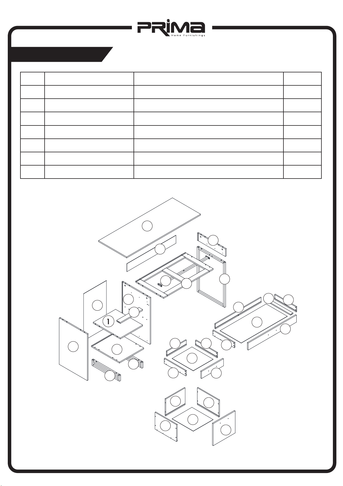
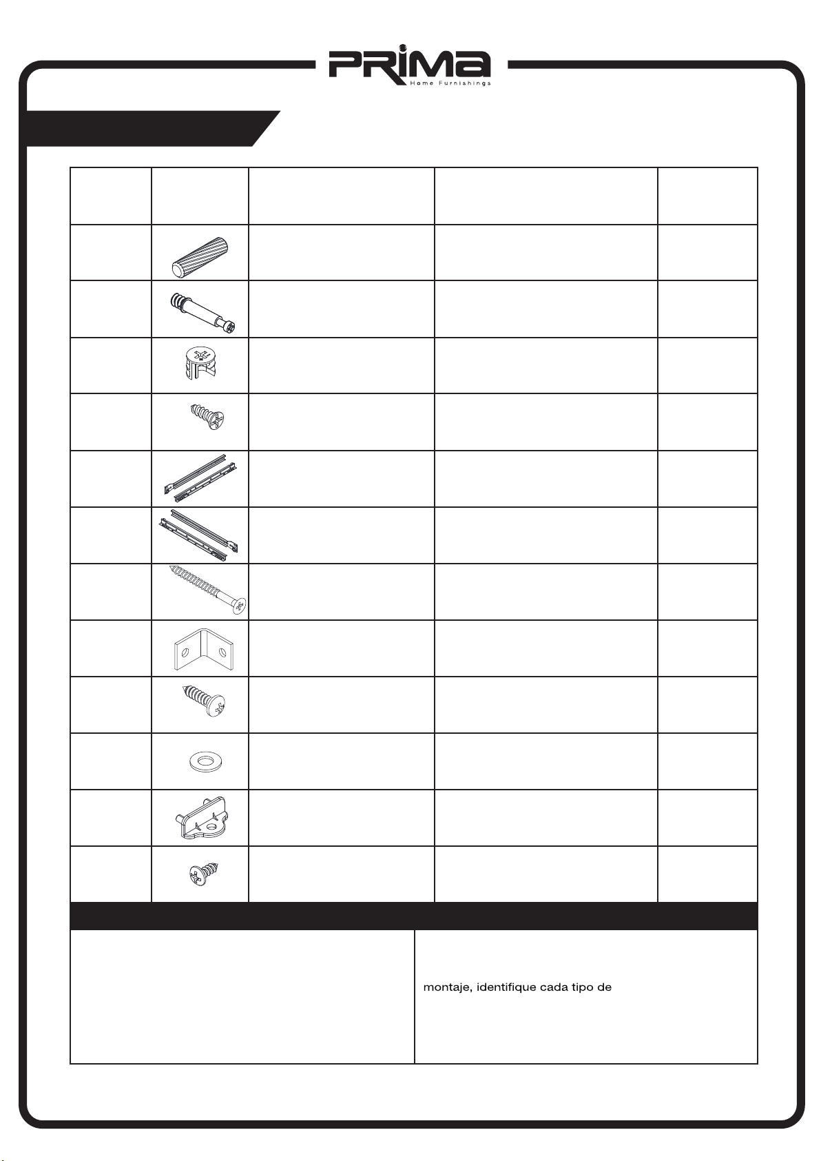
Parts list/Lista de piezas
01
ITEM DESCRIPTION DESCRIPCIÓN
QUANTITY
1
2
1
1
1
1
1
1
1
1
3
4
5
6
7
8
Fixed shelf Estante izquierdo
Rail
Gable left
Divider
Left bottom
Right bottom
Gable right
Left back panel
1
9Right back panel
Barra inferior del Cajón
Tablero izquierdo
Tablero vertical
Tablero izquierdo inferior
Marco derecho inferior
Tablero derecho
Tablero izquierdo posterior
Tablero derecho posterior
1
10 Top Panel superior
1
11 Connecting pipe Tubo de conexión
1
12 Right leg Soporte derecho
2
13 Left leg Soporte izquierdo
2
14 Upper drawer side left
Upper drawer side right
Tablero izquierdo del cajón superior
2
15 Tablero derecho del cajón superior
1
16 Upper right drawer back Tablero posterior del cajón derecho
1
17 Upper right drawer bottom rail Barra inferior del cajón largo
2
18
Upper right drawerr bottom
Tablero inferior del cajón derecho
1
19 Upper right drawer front Tablero frontal del cajón derecho