2 x Eyelet ring
Eyelet ring
=
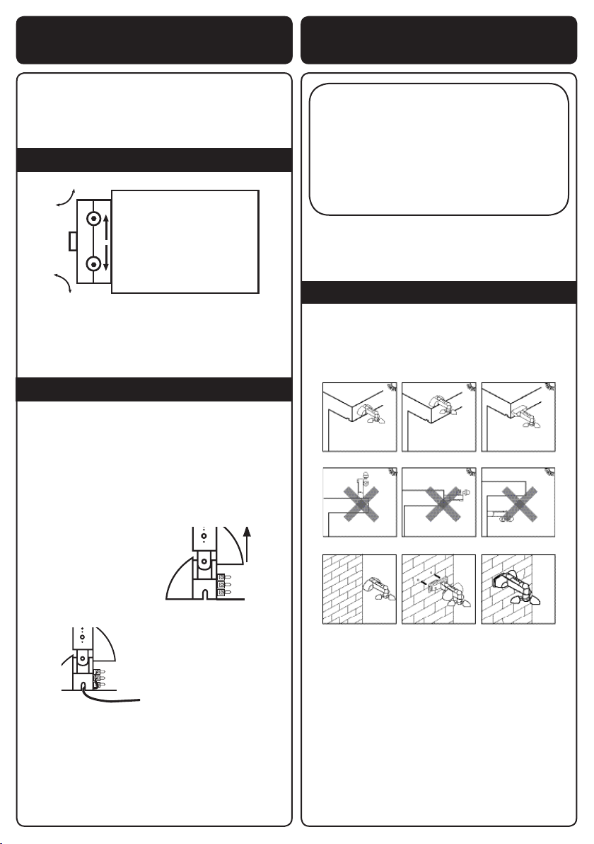
(THIS STEP APPLIES TO ELECTRIC AWNINGS ONLY)
Our awning can either be ed with a plug or wired into
the mains socket. If you choose to wire into the mains
you should consult a qualied electrician. The following
summaries how the wiring works for the wireless control
kit, indoor wall switch kit and also the wind and sun
sensor kit.
Step 6: Wiring the electrics
Step 7: Wiring the electrics – Kit A
Step 7: Wiring the electrics – Kit A
The 3 core cable can be wired into a standard 13 Amp
plug and then plugged in to an exisng socket. You
can also wire directly into the mains, complying with
any relevant regulaons. If you are unsure of these
regulaons, we recommend you consult a qualied
electrician.
If you’ve purchased a wind and sun sensor kit
please refer to the step 10.
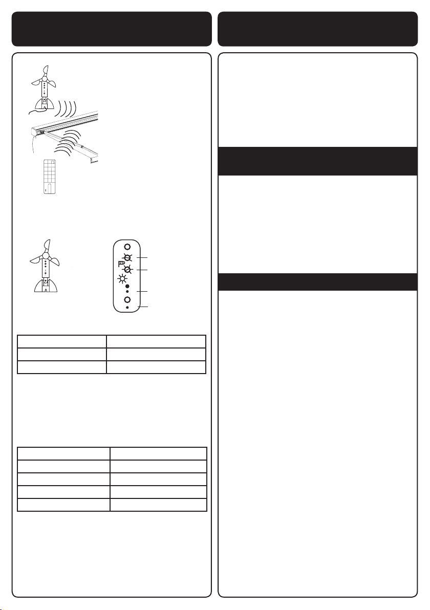
Once the power goes to the motor, give it 5 seconds,
then press “P2”, twice then press “OPEN” (on the back
of the remote zapper, remove cover), it will then be
synchronised. If you want to change the direcon, turn
the power o, and aer 10 seconds, turn the power
back on. 5 seconds later press “P2” twice and “CLOSE”
(on the remote zapper), you will nd the direcons have
changed.
2. Press “Open” or “Close” buon to extend or retract
the awning as per your requirement. Press “Pause”
(middle) to stop the awning at the posion you want it
to be.
Warning: To operate the awning, you will need to press
the buon “Open”, “Close” or “Pause” by one click. We
would recommend that you press the Pause/Stop buon
before it extends/retracts to its maximum.
3. The remote zapper is driven by a baery. If the
baery runs out of power, you will need to purchase a
new baery.
Step 8: Limit control
Can I control how far out the awning opens?
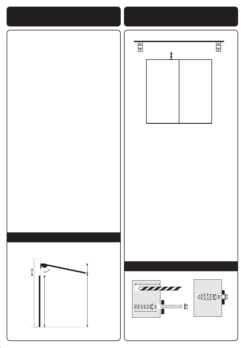
Manual awnings
With the manual awnings, you can control the posion
of the awning by simply winding out as far you want
to go. The awning will hold at whichever posion you
wind to.
Electric awnings
The electric awning will stop automacally at the pre-set
maximum extension. It will also stop automacally when
fully retracted. We would recommend that you press the
pause/stop buon before it extends to the maximum.
This will avoid the motor over heang. If you wish, you
can posion the awning at any point between maximum
extension and fully retracted by pressing the stop buon
while the awning is extending or retracng.
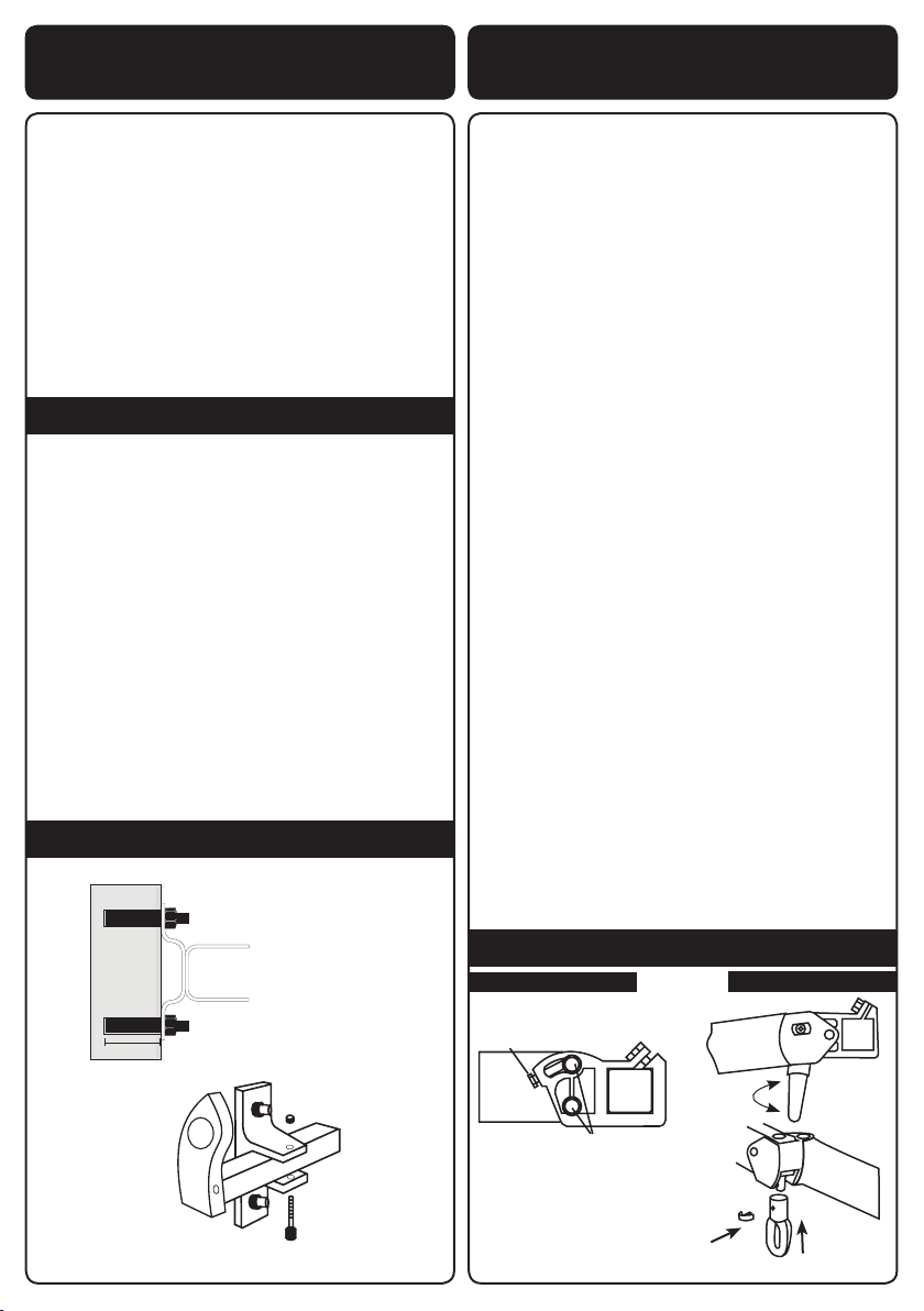
Adjusng the pre-set maximum extension and fully-
retracted posions
On the le hand end of the rotang barrel, inside the
cassee are two small hexagonal bolts marked by
direconal plus and minus signs. Rotate these bolts
gently with a hexagonal key (Green Allen key provided)
to change the maximum extension and full-retracon
points.
Always make sure you count the amount of turns while
adjusng, just in case you want to go back to the original
seng
1. (White adjustment) Retracon point: Take care not
to set this to over-retract otherwise it may cause
damage to the awning. Rotang towards the negave
will reduce the amount that the awning retracts. If
for example the awning doesn’t retract properly and
has a 1-3 inch gap then adjust the white hole to +
clockwise. For example a 50cm gap will need approx
40 turns.
If you wish to set the awning so that it retracts
further, we recommend that you fully retract the
awning with the current seng allowing the motor to
turn o automacally. Then turn the hexagonal key
one quarter turn at a me towards the posive. This
should cause the front bar automacally to move in a
$UP
/RFNLQJ1XWV
-DFN%ROW
5HWUDFW
([WHQG
P2
P2
3 core cable wire
Standard plug socket
(Plug not included)
Awning
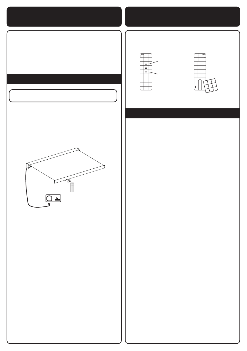
Remote Zapper
Front of remote
Open
Pause/Stop
Close
P2
Back of remote
Back cover
Step 8: Limit control