Princeton Applied Research VersaSTAT 3 User manual

VersaSTAT 3
Hardware Manual
P/N 224182

VersaSTAT 3 Hardware Manual
Contents
Safety Instructions and Symbols ...........................................................................................................4
Cleaning Instructions................................................................................................................................4
1. INTRODUCTION ....................................................................................................................................5
1.1. General ...........................................................................................................................................5
1.2. Hardware Circuitry .......................................................................................................................5
1.2.1. Potentiostatic mode .............................................................................................................6
1.2.2. Galvanostatic mode..............................................................................................................7
1.3. Software .........................................................................................................................................7
1.4. Polarity Convention ......................................................................................................................7
1.5. Inspecting Your New Instrument ..............................................................................................8
1.6. Maintenance, Service, and Support..........................................................................................8
1.7. About this manual ........................................................................................................................8
2. SAFETY AND COMPONENT PLACEMENT.........................................................................................10
2.1. Safety Considerations................................................................................................................10
2.1.1. Line Voltage Settings and Fuses .....................................................................................10
2.1.2. Defects and Abnormal Stresses.......................................................................................11
2.2. Component Placement...............................................................................................................11
2.2.1. Ventilation ............................................................................................................................11
2.2.2. Radio Frequency Interference..........................................................................................12
2.2.3. Transient Sensitivity ..........................................................................................................13
3. INSTALLATION ....................................................................................................................................15
3.1. Enabling the USB port on your PC ..........................................................................................15
3.2. Connectors and Indicators........................................................................................................15
3.2.1. Rear Panel ............................................................................................................................15
3.2.2. Front Panel ...........................................................................................................................16
3.3. Connecting to the PC and Cell .................................................................................................17
3.3.1. Connecting to the PC .........................................................................................................17
3.3.2. Connecting the Cell ............................................................................................................17

VersaSTAT 3 Hardware Manual
4. SPECIFICATIONS AND PINOUTS .....................................................................................................22
4.1. Electronic Specifications............................................................................................................22
4.1.1 System Performance ...............................................................................................................22
4.1.2. Power Amplifier .......................................................................................................................22
4.1.3. Voltage Control ...................................................................................................................22
4.1.4. Current Control ...................................................................................................................22
4.1.5. Differential Electrometer ...................................................................................................22
4.1.6. Voltage Measurement ........................................................................................................23
4.1.7. Current Measurement........................................................................................................23
4.1.8. iR Compensation.................................................................................................................23
4.1.9. Potential/Current Control ..................................................................................................23
4.1.10. Impedance Specifications (if impedance option available) .....................................23
4.2. Physical and Power Specifications...........................................................................................24
4.3. Standard Environmental Conditions .......................................................................................24
4.4. AUXILIARY INTERFACE Pinouts ...............................................................................................25
4.5. Cell Cable Pinouts .......................................................................................................................25
5. AVAILABLE OPTIONS .........................................................................................................................26
5.1 2A High Current Option ..............................................................................................................26
5.2 FRA Option.....................................................................................................................................26
5.3 Advanced Auxiliary Interface Option .......................................................................................26
5.4 Power Booster Options ...............................................................................................................27
5.5 VersaSTAT LC Low Current Interface ......................................................................................27
Appendix 1................................................................................................................................................29
VersaSTAT 3 External Power Booster Connections......................................................................29

VersaSTAT 3 Hardware Manual
VersaSTAT 3 Hardware Manual 4
Safety Instructions and Symbols
This manual contains up to three levels of safety instructions that must be observed in
order to avoid personal injury and/or damage to equipment or other property. These are:
DANGER Indicates a hazard that could result in death or serious bodily harm if the
safety
instruction is not observed.
WARNING Indicates a hazard that could result in bodily harm if the safety instruction
is
not observed.
CAUTION Indicates a hazard that could result in property damage if the safety
instruction
is not observed.
Please read all safety instructions carefully and make sure you understand them fully
before attempting to use this product.
Cleaning Instructions
WARNING: Using this instrument in a manner not specified by the manufacturer
may impair the protection provided by the instrument.
To clean the instrument exterior:
Unplug the instrument from all voltage sources.
Remove loose dust on the outside of the instrument with a lint-free cloth.
Remove remaining dirt with a lint-free cloth dampened in a general-purpose detergent
and water solution. Do not use abrasive cleaners.
CAUTION: To prevent moisture inside of the instrument during external cleaning,
use only enough liquid to dampen the cloth or applicator.
Allow the instrument to dry before reconnecting the power cord.

VersaSTAT 3 Hardware Manual
VersaSTAT 3 Hardware Manual 5
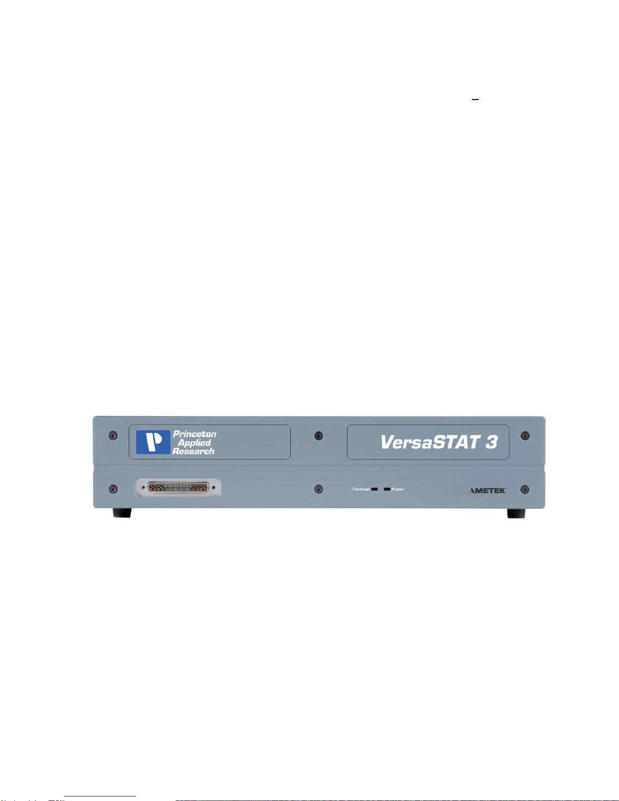
1. INTRODUCTION
The VersaSTAT 3 (Figure 1), teamed with the VersaStudio software package, comprises
a simple, flexible, and extremely powerful system for performing a wide range of
electrochemical techniques. The VersaSTAT 3 is a potentiostat/galvanostat with an
optional frequency response analyzer (FRA) contained in a single unit. It is controlled
from any suitably equipped PC by a Universal Serial Bus (USB) interface using the
VersaStudio electrochemistry software package.
Figure 1. VersaSTAT 3
1.1. General
The host computer provides memory, data processing, input-output, and interface
capabilities. The VersaSTAT 3 electronically controls the measurement under the
direction of the software and parameter values entered from the host computer. The
computer must be equipped with a USB port, and the operating system must support the
USB interface.
1.2. Hardware Circuitry
The VersaSTAT 3 circuitry includes:
Two 16-bit digital-to-analog converters (DACs) for versatile waveform generation.
Three 16-bit analog-to-digital converters (ADCs) to measure current (I), potential (E),
SYNC ADC INPUT.
An onboard microprocessor to perform the experiment defined by the operating
software.

VersaSTAT 3 Hardware Manual
VersaSTAT 3 Hardware Manual 6
Onboard memory to store the programmed parameters and data point values.
The VersaSTAT 3 operates with VersaStudio in either the potentiostatic or galvanostatic
mode, described below.
1.2.1. Potentiostatic mode
In this mode, the VersaSTAT 3 controls the potential at the working-sense electrode with
respect to the reference electrode (see Figure 2). The counter electrode is driven to the
potential required (consistent with the + 12 V compliance of the control amplifier) to
establish the desired working potential. The range over which the working electrode
potential can be controlled is + 10 V.
-
+
WORKING
I OUT
I OUT
I/E CONVERTER
CURRENT RANGES (EXAMPLE)
2 mA
200 uA
20 uA
2 uA
200 nA
20 nA
E IN
E IN -
+
POWER AMP
Cell Switch
COUNTER
SINGLE ENDED
-
+
REFERENCE
SENSE
E OUT
E OUT
DIFFERENTIAL
ELECTROMETER
Figure 2. Potentiostat-Mode Block Diagram

VersaSTAT 3 Hardware Manual
VersaSTAT 3 Hardware Manual 7
1.2.2. Galvanostatic mode
In galvanostatic operation, the VersaSTAT 3 controls the current between the counter
and working electrodes at the specified fraction of the selected current range (up to the
maximum of the current range; see Figure 2). The counter electrode is driven to the
potential required (consistent with the + 12 V compliance of the control amplifier) to
establish the desired cell current. The reference electrode is not used in the control loop,
but is usually used to measure the potential at some point in the electrochemical cell
relative to the working-sense connection point.
Figure 3. Galvanostat-Mode Block Diagram
1.3. Software
The VersaSTAT 3 isfullycompatible with the VersaStudio software only. The VersaSTAT
3 will not operate with any other software other than that specified in this manual or the
most recent documentation available on the web site
(http://www.princetonappliedresearch.com). Likewise, the VersaSTAT 3 does not have an
open command set to allow user programming outside of the VersaStudio software. The
software is designed specifically to work with Windows XP, Windows 7 and Windows 8,
but it is highly recommended that Windows XP or Windows 7 be used.
1.4. Polarity Convention
The VersaSTAT 3 hardware follows the American polarity convention. (Positive current is
cathodic; that is, a current is defined as positive if reduction is taking place at the working

VersaSTAT 3 Hardware Manual
VersaSTAT 3 Hardware Manual 8
electrode. Negative current is anodic; that is, a current is defined as negative if oxidation
is taking place at the working electrode. If the working electrode is driven positive with
respect to the equilibrium potential, the resulting current is anodic. If the electrode is
driven negative with respect to the equilibrium potential, the resulting current is cathodic.)
In complex electrochemical systems, there might be more than one equilibrium system.
Where this is the case, either polarity with respect to the equilibrium potential could give
rise to anodic or cathodic current, according to the systems’ characteristics.
1.5. Inspecting Your New Instrument
As soon as you receive your new VersaSTAT 3, inspect it for shipping damage. If any
damage is noted, immediately notify Princeton Applied Research and file a claim with the
carrier. Save the shipping container for possible inspection by the carrier.
WARNING: If your instrument has been damaged, its protective grounding might
not work. Do not operate damaged equipment! Tag it to indicate to a
potential user that it is unsafe to operate.
1.6. Maintenance, Service, and Support
The VersaSTAT 3 has been designed for optimum reliability and requires no periodic
maintenance. There are no user-serviceable parts in this instrument. Breaking the
seal by opening the cover will void your warranty! Contact the factory service
department or the affiliate in your area if your unit needs service (see the Warranty in
Section 5. for more information).
Remember that our worldwide staff continues to support you after you have purchased
your instrument. We provide top quality service, applications support, and a variety of
helpful information in the form of application notes, technical notes, and training materials.
For more information, visit our website at www.princetonappliedresearch.com.
1.7. About this manual
Chapter 2 describes recommended safety precautions for operating this instrument,
including the provision of adequate ventilation. It also tells how to deal with transients on
the power line, and discusses the unlikely possibility of the instrument causing radio
frequency (RF) interference.

VersaSTAT 3 Hardware Manual
VersaSTAT 3 Hardware Manual 9
Chapter 3 shows how to set up the hardware. It describes the functions of the
connections and indicator lights, and shows how to connect the VersaSTAT 3 to the host
computer and test cell.
Chapter 4 gives the physical and electrical specifications of the VersaSTAT 3 including
the AUXILIARY INTERFACE connector pinouts.
As noted above, the VersaSTAT 3 is completely computer controlled; operation and
experimental procedures are covered in the software section of this manual.

VersaSTAT 3 Hardware Manual
VersaSTAT 3 Hardware Manual 10
2. SAFETY AND COMPONENT PLACEMENT
This chapter lists safety precautions for use when operating the VersaSTAT 3; please
read them. There are suggestions for system component placement and information on
possible RF interference and transient sensitivity.
2.1. Safety Considerations
2.1.1. Line Voltage Settings and Fuses
The VersaSTAT 3 has a Corcom™ Power Entry Module on the left side of the rear panel.
The Corcom module (pictured below) contains the power connector and two line fuses.
The VersaSTAT 3 automatically detects the correct line voltage and frequency, so
there is no line voltage changes required in the Corcom.
The VersaSTAT 3 is supplied with the line voltage fuses in place, as well as extra fuses
supplied with each unit. For fuse replacement:
For 100 –120 Vac line voltages, use a 2.0 A T (slow-blow) fuse (Littlefuse® type
213, 5 x 20 mm or equivalent).
For 220 - 240 Vac line voltages, use a 1.0 A T (slow-blow) fuse (Littlefuse® type
213, 5 x 20 mm or equivalent).
Caution: Do not use makeshift fuses or short-circuit the fuse holders
To replace a fuse:

VersaSTAT 3 Hardware Manual
VersaSTAT 3 Hardware Manual 11
1. Disconnect the instrument for the ac power source.
2. Use a small flat-blade screwdriver or similar tool to pop open the module door (as
shown in the picture above).
3. The line fuse is in a plastic fuse holder “drawer” marked with an arrow ( ).
Gently pull the fuse holder out, remove the old fuse, and press in the
replacement.
4. Slide the fuse holder back into the module, and close the module door. You are
now ready to reconnect the instrument to the ac power source.
2.1.2. Defects and Abnormal Stresses
WARNING: If your instrument has been damaged, its protective grounding might
not work. Do not operate damaged equipment! Tag it to indicate to a
potential user that it is unsafe to operate.
The VersaSTAT 3’s ground protection is likely to be impaired if, for example, the
instrument
shows visible damage
fails to perform the intended measurement.
has been subjected to prolonged storage under unfavorable conditions, or
has been subjected to severe transport stresses.
The instrument should not be used until its safety has been verified by qualified service
personnel.
2.2. Component Placement
Before assembling the system, give some thought to component placement. You will of
course need convenient access to the computer keyboard and, if applicable, the printer.
Depending on the application, you might also need to connect and disconnect the cell
leads regularly.
When you are satisfied that the system is ready to install, connect the unit according to
the instructions in Chapter 3.
NOTE: The standard system does not include an electrochemical cell. You must supply
a suitable cell and electrodes.
2.2.1. Ventilation

VersaSTAT 3 Hardware Manual
VersaSTAT 3 Hardware Manual 12
VersaSTAT 3 specifications apply at the nominal line voltage + and at a temperature of
25oC (77o F) unless otherwise noted. Ambient temperature must not exceed 50oC (122o
F). See Section 4.3 for more detailed environmental specifications.
To maintain a safe operating temperature, allow some free space (minimum 10 cm) at
either side of the VersaSTAT 3 for adequate air circulation. There must be adequate
circulation between the spaces at the sides of the instrument and the ambient laboratory
air. In a typical bench top installation, these requirements are satisfied with a large safety
margin.
CAUTION Because the ventilation for the VersaSTAT 3 is on the side panels, rack
mounting in an enclosed cabinet is not recommended.
2.2.2. Radio Frequency Interference
In a typical application,it is unlikely that the VersaSTAT 3 will act as a source of noticeable
RF interference. However, when operated near particularly sensitive equipment,
interference from the VersaSTAT 3 could be a problem.
Below is a discussion of steps you can take to minimize that interference.
Interference below about 10 MHz is most likely to be caused by RF currents flowing in
the input and output cables or in the power line cord.
If excessive noise pickup is present, try decoupling the power line with an external filter.
At frequencies below 100 kHz, an external isolation transformer could be helpful.
WARNING: To reduce the risk of potentially dangerous electrical shock, only a
qualified service technician should perform this work, and then only
with the instrument disconnected from all sources of power.
At frequencies above 10 MHz, these measures might not suffice to prevent radiation from
being a problem, particularly at VHF frequencies. Additional measures will then be
required. Shielding is generally effective. A suitable shield can be constructed using
metal foil, wire screening, or similar materials.
Once the instrument is completely surrounded by the shield (taking care not to unduly
restrict ventilation), the only additional requirement is to install low-pass filters where lines
pass through the shield (all openings through the shield should be as small as possible).
A capacitor between a line and the shield can function as a suitable low-pass filter. The
leads of the capacitor should be as short as possible. We suggest using coaxial feed
through capacitors.

VersaSTAT 3 Hardware Manual
VersaSTAT 3 Hardware Manual 13
In the case of a signal lead, it is essential that the capacitor’s value be such as to attenuate
the interference frequencies without unduly attenuating critical frequency components of
the signal itself.
NOTE: Keep the filter capacitor leads short! Long leads establish sizable ground
loops and could additionally act as radiating antennae.
Coaxial cables are a special case in that the cable shield acts as an extension of the
enclosure shield. Thus, the filter can be counted in a shielded box fitted with coaxial
connectors without undue concern for keeping the box extremely close to the enclosure.
If more convenient, it can be located at some distance from the enclosure as long as the
integrity of the coaxial shield is maintained.
The preceding techniques are extraordinary measures that should be required only in
unusual cases. If they are applied with care, RF interference should be reduced to an
acceptably low level in all but the most critical applications. Contact the Customer Service
Department for advice in the case of a problem that does not yield to these measures.
2.2.3. Transient Sensitivity
Princeton Applied Research instruments are designed and constructed to ensure normal
operation in the presence of moderate transient levels. Although these provisions are
sufficient for operation in most places where the equipment is used, it is certainly possible
for transient levels in particular environments to be so severe that they make reliable
operation uncertain. There are three general types of high-level transients:
1. Static discharge
Transients from this source generally affect input or output circuits, input circuits
that include MOS field-effect transistors to achieve high input impedance are
particularly susceptible to damage from this source. Damage typically occurs when
the charge built up on a user’s body discharges into an input or output connector
as a connection is being made. Among the factors determining the tendency for
charges to build are the kind of clothing fabrics worn, shoe materials, and the
materials in the floor or floor covering.
2. High-level transients generated internal to the place of use
Such transients almost always enter the instrument via the line cord. Possible
sources include heavy-duty electric motors, RF equipment, diathermy machines,
arc welder, spark chambers, and others.
3. Lightning
Transients caused by lightning almost always enter the instrument via the line cord.
Static discharge problems can sometimes be avoided by judiciously selecting the floor
covering in the work area. The simplest approach to the problem is to discharge your

VersaSTAT 3 Hardware Manual
VersaSTAT 3 Hardware Manual 14
body by touching a grounded metal object just before touching the instrument, particularly
when making connections to the cell. External line-transient filters can generallysuppress
transients that enter the instrument via the line cord. A suitable transient suppressor is
available from Princeton Applied Research. Various kinds of power-line conditioners are
also commercially available.

VersaSTAT 3 Hardware Manual
VersaSTAT 3 Hardware Manual 15
3. INSTALLATION
This chapter describes the VersaSTAT 3 connectors and indicators and shows you how
to connect it to the host PC, electrochemical cell, and other equipment you might wish to
use with it. The pinouts for AUXILIARY INTERFACE connector and cell cable connector
are listed in Sections 4.4. and 4.5., respectively.
3.1. Enabling the USB port on your PC
Some PC manufacturers ship their PCs with the USB port disabled. Check for this before
trying to use the VersaSTAT 3. If the port is disabled, follow the manufacturer’s
instructions for enabling it.
3.2. Connectors and Indicators
3.2.1. Rear Panel
The VersaSTAT 3 rear panel is shown in Figure 4.
FIGURE 4. VersaSTAT 3 Rear Panel
3.2.1.1. INPUT POWER
120-240-V; the supplied AC power cord can be connected to 120-
240V AC.
3.2.1.2. USB
Attach the supplied USB cable to this connector and to the USB
connector on the PC. You can connect to and disconnect from the
PC without shutting down or restarting Windows or VersaStudio.
3.2.1.3. SYNC ADC INPUT
This BNC allows you to monitor an auxiliary signal in the + 10 V range
with 16-bit resolution. This signal is monitored synchronously with
the
E and I channels.
VersaSTAT 3 Hardware Manual
VersaSTAT 3 Hardware Manual 16
3.2.1.4. DAC OUTPUT
Rear-panel BNC delivers a precise DC voltage in the + 10 V range.
This output can be used to control the rotation speed of rotating disk
electrodes (RDEs). CAUTION: The voltage at this connection will
be random at power-on until the system fully boots (~ 1 min after
power-on). As a result, no connection should be made until system
has completely booted, or in the case of an RDE (i.e., the 616/636
systems), leave the power off on the RDE until the system is
completely booted.
3.2.1.5. AUXILIARY INTERFACE
This DB9 female connector provides several functions including the
signals required to drive a Model 303A Static Mercury Drop
Electrode. If using a Model 303A, you must connect the electrode to
the AUXILIARY INTERFACE connector via the Model 507 Interface.
AUXILIARY INTERFACE can also turn the Model 616 Rotating Disk
Electrode on and off with theSTIR signal issued with the VersaStudio
software. See Section 4.4. for the pin assignments.
3.2.2. Front Panel
The VersaSTAT 3 front panel is shown in Figure 5.
FIGURE 5 VersaSTAT 3 Front Panel
3.2.2.1. CELL CABLE Connector The cell cable connector provides a
means of connecting a cell cable to the instrument. The cell cable is
described in more detail below.
3.2.2.1. INDICATORS
OVERLOAD (OVLD) This LED lights if the working electrode current
exceeds 2x the full-scale current range.

VersaSTAT 3 Hardware Manual
VersaSTAT 3 Hardware Manual 17
POWER (PWR) This indicator lights when the VersaSTAT 3
is powered on.
3.3. Connecting to the PC and Cell
This section gives instructions on connecting the VersaSTAT 3 to the host PC and to
electrochemical cell and other equipment.
WARNING: For operator and equipment safety, power to all instruments should
be off when connecting or disconnecting cables.
3.3.1. Connecting to the PC
The VersaSTAT 3 is shipped with a standard USB cable. Connect it between the rear-
panel USB connector and a USB port on the PC. As noted above, it is not necessary to
shut down and restart Windows or VersaStudio.
3.3.1.1. Installing the USB Driver
The first time the VersaSTAT3 is connected to the host PC and powered on, Windows®
should display a “Found New Hardware” message, and request driver installation. Upon
this request, insert the VersaStudio CD into the CD-ROM drive, and select “Automatic”
to install the driver. This driver should be located in the C:\Program Files\Princeton
Applied Research\VersaStudio\ folder.
3.3.2. Connecting the Cell
To connect the cell cable (part no. 223762) to the VersaSTAT 3:
1. Make sure the POWER switch is off.
2. Match and attach the D connector side of the Cell cable to the front of the
VersaSTAT 3, and secure the screws on either side.
3. After cell cable is connected to front panel, power the unit on and let it boot fully
(approximately 1 min to boot up) before connecting a cell to the leads of the cell
cable.
CAUTION: Having a cell connected at power-on or at power-off should be
avoided to prevent any voltage or current spikes from reaching the cell, or
in the case of energy storage devices (such as batteries, capacitors, or fuel
cells), preventing spikes from discharging back into the VersaSTAT 3 and
causing damage to the instrument.
4. The opposite end of cell cable is color-coded at the tip as follows:

VersaSTAT 3 Hardware Manual
VersaSTAT 3 Hardware Manual 18
Green –Working (WE) electrode lead. This lead connects to the electrode of
interest at which the desired reactions will occur. The current (I) is measured
through the WE.
Red –Counter (CE) electrode lead. This lead connects to the electrode
opposite the WE and controls the power output of the VersaSTAT 3.
Gray –Sense (SE) electrode lead. This usually connects to the working
electrode (the combination often referred to as the working-sense), and is a
component of the differential amplifier that measures/controls the voltage
between itself and the reference electrode.
White –Reference (RE) electrode lead. This connects to the reference
electrode, a component of the differential amplifier that measures/controls the
voltage between itself and the sense electrode.
Black –Ground lead. The use of the ground lead depends on the application,
but it is not ordinarily used in most experiments. It can be used to supply a
ground point to a Faraday shield for the experimental cell, and is used in some
open circuit experiments to form a zero-resistance ammeter (ZRA).

VersaSTAT 3 Hardware Manual
VersaSTAT 3 Hardware Manual 19
5. The following descriptions and figures explain how to connect a two-, three-, or
four-terminal electrochemical cell to the terminals of the VersaSTAT 3 cell cable.
a) Batteries, capacitors, resistors, fuel cells, and some sensors are generally
connected using a two-terminal connection (Figure 6). The connectors for the
cable leads are designed to allow easy interconnection of the working/sense
and reference/counter leads. Note: If your cell has low impedance (battery)
and/or your experiment generates currents inexcess of 100mA, do not connect
the leads into one another for a two-terminal connection. Instead, connect the
leads independent of one another to their proper terminal at the cell to prevent
voltage offsets that can result from milliohms of contact resistance in a “piggy-
back” connection as shown below.
Figure 6. Two-Electrode Connection
b) General aqueous electrochemistry, corrosion experiments, and most EIS
experiments are connected using a three-terminal connection (Figure 7). The
voltage at the working-sense is controlled relative to a stable reference
electrode positioned in close proximity to the working electrode.

VersaSTAT 3 Hardware Manual
VersaSTAT 3 Hardware Manual 20
Figure 7. Three-Electrode Connection
c) There are some applications for which a four-terminal (Figure 8) connection
is required. In this case, the sense electrode serves as a second reference
electrode, useful for controlling the potential between the reference and sense
(for instance, in controlling the potential across a membrane in a H-cell setup).
Note: Running experiments in this mode requires that the Electrometer
Mode setting in the software be set to Differential for the correct potential
to be applied and read.
Figure 8. Four-Electrode Connection
Table of contents
Popular Laboratory Equipment manuals by other brands

Bruker
Bruker Ascend 400'54 user manual

Agilent Technologies
Agilent Technologies Infinity Binary Pump VL 1290 user manual

Hach
Hach DR 3900 Basic user manual

VWR
VWR INCU-Line IL 23R Cool instruction manual

ThermoFisher Scientific
ThermoFisher Scientific QuantStudio 6 Pro user guide

Bruker
Bruker SamplePro hr-MAS Service manual


