Prins VSI-2.0 User manual

MAKE OF AUTOMOBILE:
Volkswagen
TYPE:
Tiguan
PISTON DISPLACEMENT:
1400
NUMBER OF VALVES:
16
ENGINE NUMBER:
CAXA / CAXC
FIRING ORDER:
1-3-4-2
TRANSMISSION TYPE ( MT / AT )
MT
VEHICLE CATEGORIES M or N
M
TYPE VSI INJECTOR ( COLOUR )
KN9 52cc
VERSION ( LPG )
LPG-DI 2.1
INJECTION SYSTEM:
BOSCH MED 17.5.5 / MED 17.5.20
MODEL YEAR:
2011-
SYSTEM APPROVAL NUMBER ( R115 )
E4-115R-000020 / VSI-LPG 31
LOCATION SYSTEM STICKER
right side, centre door post
ENGINE SET NUMBER
366/120007/A
NUMBER :
076/2613400
DATE :
2014-06-20
Copyright © Prins Autogassystemen B.V. 2014 VERSION NR :
2013-08-20 C

TABLE OF CONTENTS
General instructions............................................................................................................................. 2
Required equipment / tools / materials for installing a complete system............................................. 3
Vehicle check....................................................................................................................................... 3
Base diagram....................................................................................................................................... 4
VSI approval numbers ......................................................................................................................... 5
Mounting and connection points.......................................................................................................... 6
Mounting the reducer........................................................................................................................... 7
Water connections ............................................................................................................................... 8
Overpressure / MAP connection.......................................................................................................... 9
Mounting the inlet manifold couplings................................................................................................ 10
Mounting the VSI injector rail............................................................................................................. 11
Mounting the Keihin filter unit............................................................................................................. 12
LPG hoses ......................................................................................................................................... 13
LPG piping ......................................................................................................................................... 14
Mounting the AFC & Injection module ............................................................................................... 15
Mounting the fuel selection switch..................................................................................................... 16
Electrical connections ........................................................................................................................ 17
Electrical connections ........................................................................................................................ 18
Electrical connections ........................................................................................................................ 19
Electrical connections ........................................................................................................................ 20
Checklist after installation.................................................................................................................. 21
Trouble code chart............................................................................................................................. 22
FOR EXPLANATION AND CIRCUIT DIAGRAMS SEE : INSTALLATION MANUAL GENERAL PART 1 / 2
EXPLANATION OF SYMBOLS :
= IMPORTANT, CAUTION

PAGE 2
076/2613400
Copyright © Prins Autogassystemen B.V. 2014
VW Tiguan 1.4 CAXA / CAXC
2
General instructions
The installation of the system shall be done in accordance with the installation manual provided by Prins
Autogassystemen.
This manual is based on Dutch regulations, always install the system in accordance to the local regulations.
Always download the “general manual 1/2 “ from our website for basic instructions and diagrams.
Always disconnect the battery when installing the LPG system. Make sure the ignition key is outside the car.
Be aware of central door locking, radio / telephone memory code, alarm system.
Do not place the main fuse into the fuse holder before having completed the installation of the VSI system.
The VSI computer has to be activated by means of the diagnosis software.
In the unlikely event the VSI computer fails, it will automatically switch over to petrol.
Never disconnect the VSI computer connector, unless you have removed the main fuse.
When installing the VSI wiring harness, ensure that it does not run near any of the ignition components.
Solder and insulate all electrical connections.
The wires in the loom are provided with numbers and text. The text on the wire explains the
function of the wire. The wire harness is not model specific, therefore is it may be necessary to
adjust the length of the wires. Ensure maximum care is taken when connecting wiring.
Make professional joints using solder and shrink sleeve. Do not stretch the wiring harness.
No component of the LPG-system shall be located within 100 mm of the exhaust or similar heat source,
unless such components are adequately shielded against heat.
Remove any internal burrs, after having shortened the LPG pipe. (This guarantees the maximum flow
through the pipe without pollution.)
If holes have to be drilled (wear safety glasses) for installing brackets, etc., the drilled holes must always be
treated with an anti-corrosion agent, after the chips have been removed ( especially when mounting a
exterior filler into body work).
After having completed the installation, check the whole system for gas leakage; use a gas leak detection
device. Also check for leak of engine coolant, petrol and air.
Fitting and maintenance is only allowed by Prins Autogassystemen selected LPG engineers.
Failure to follow the instructions in this manual can result in a poor or non-working gas installation
or a dangerous situation.
For maintenance instructions and filter registration see owner manual.
Prins Autogassystemen is not responsible for any damages to people or objects as a result of changes to
Prins products.
Check our website regularly for diagrams, certificates, updates, info-bulletins and product information.
Please fill in the warranty card completely and return it within 8 days after installation.

PAGE 3
076/2613400
Copyright © Prins Autogassystemen B.V. 2014
VW Tiguan 1.4 CAXA / CAXC
3
Required equipment / tools / materials for installing a complete system
-Complete workshop toolbox ( wrenches, screwdrivers, cutters, pliers, ratchet, sockets )
-Car lift
-Portable computer : operating on Windows 98,W2000 or XP.
Internal memory : 16 Mb or more
Memory HD space : 5MB
Screen : 256 colours, advise colours 16 bits or more
Com port : 1 free COM port 1 or COM port 2 with a 9 or 25 pins connector
-Vehicle fuel system scan tool or OBD scan tool Prins ( part nr. 099/99928 )
-Exhaust gas analyser
-Multimeter
-Oscilloscope
-Prins VSI diagnostic software
-Prins VSI serial interface
-Prins VSI break out box ( part nr. 080/70090 )
-Torque wrench ( 10Nm )
-Portable light
-Assortment drill bits 4 to 12 mm
-Assortment cutters ( ø 20, 30, 50, 70 mm )
-Punching tool ø 70 mm
-Round file
-Portable drill or pneumatic drill
-Thread cutting device ( male M6x1, M8x1, M10x1 )
-Pipe-flaring tool ( for 6 and 8 mm copper pipe )
-Air gun
-Vacuum cleaner
-Hot air gun
-Allan spanner for inlet couplings 3,5mm ( part nr. 099//9970 )
-Reducer adjustment tool ( part nr. 099/9960 )
-Molex extraction tool for VSI switch connector ( part nr. 090/9929 )
-Soldering iron, soldering tin
-Wire-stripping pliers
-Adhesive tape
-Adhesive sealant
-Thread locking compound
-Anti-corrosion agent / black body coating
-Gas leak detection device or foam leak spray
-Shrink sleeves
-Engine coolant
Vehicle check
-Check the vehicle drivability on petrol
-Check the fuel system for error codes ( scan tool )
-Check if the catalytic converter is in good condition ( exhaust gas analyzer )
-Check the condition of the ignition system ( spark plugs, cables, coil )

PAGE 4
076/2613400
Copyright © Prins Autogassystemen B.V. 2014
VW Tiguan 1.4 CAXA / CAXC
4
Base diagram

PAGE 5
076/2613400
Copyright © Prins Autogassystemen B.V. 2014
VW Tiguan 1.4 CAXA / CAXC
5
VSI approval numbers
Reducer VSI LPG Prins : E4-67R-010054
Lock-off valve OMB : E8-67R-014327
Lock-off valve Valtek : E4-67R-010041
Injector rail Prins : LPG E4-67R-010093
CNG E4-110R-000021
Filter unit T1 / T2 Prins : LPG E4-67R-010096
CNG E4-110R-000028
Filter unit Keihin : LPG E4-67R-010177
CNG E4-110R-000091
Injector Keihin : LPG E4-67R-010310
CNG E4-110R-000295
AFC Prins: LPG E4-67R-010098
CNG E4-110R-000083
LPG hoses Tubithor :LPG E13-67R-010145
CNG E13-110R-000017
Rubia : LPG E4-67R-010068
CNG E4-110R-000003

PAGE 6
076/2613400
Copyright © Prins Autogassystemen B.V. 2014
VW Tiguan 1.4 CAXA / CAXC
6
Mounting and connection points
A : Reducer
I : Wake-up
B : Filter unit
J : “-“ interruption petrol injectors
C : Injector rail
K : Overpressure coupling
D : AFC
L : R115 Approval sticker
E : Injection module
M : Grommet
F : Water connections
N : MAP signal
G : “+” ignition ( 13 )
P : Petrol high pressure sensor signal
H : Engine speed signal / RPM
Q : Petrol low pressure sensor signal
R115 approval sticker :
Right side centre door post
PAGE 7
076/2613400
Copyright © Prins Autogassystemen B.V. 2014
VW Tiguan 1.4 CAXA / CAXC
7
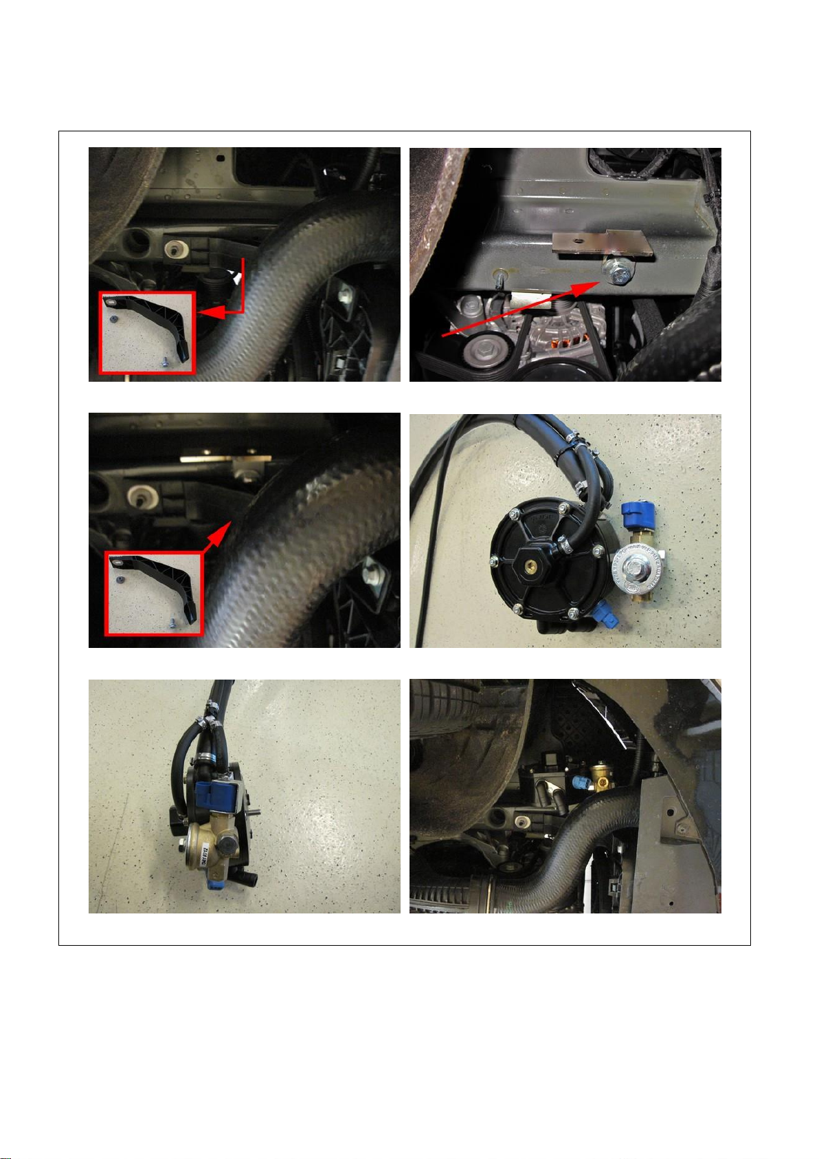
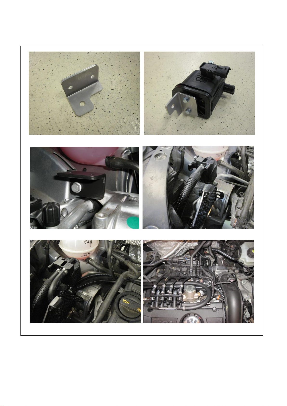
Mounting the reducer
Remove plastic support (if present). Mount reducer bracket with M10 bolt and washer.
Mount back plastic support. Connect hoses to reducer.
Connect hoses to reducer. Mount reducer with nut and spring washer to reducer bracket.
PAGE 8
076/2613400
Copyright © Prins Autogassystemen B.V. 2014
VW Tiguan 1.4 CAXA / CAXC
8
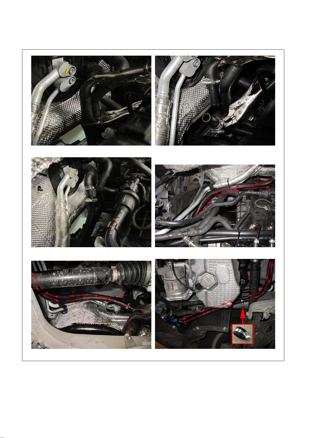
Water connections
Cut lower heater hose connection against firewall. Mount 2x 16x16mm water connectors.
Mount water hoses to just mounted connectors.Water hose routing. Fixate with pull-straps.
Water hose routing. Mount hoses to reducer. Fixate hoses with clamp.
PAGE 9
076/2613400
Copyright © Prins Autogassystemen B.V. 2014
VW Tiguan 1.4 CAXA / CAXC
9
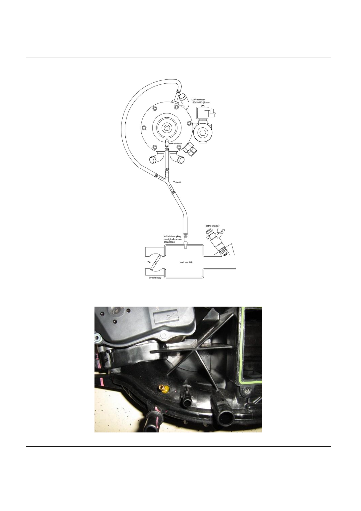
Overpressure / MAP connection
Remove the inlet manifold. Drill a hole for the overpressure and MAP coupling, see picture, Ø5mm drill, cut
M6x1 threat, install couplings with a locking compound.

PAGE 10
076/2613400
Copyright © Prins Autogassystemen B.V. 2014
VW Tiguan 1.4 CAXA / CAXC
10
Mounting the inlet manifold couplings
Remove the inlet manifold. Carefully remove the heater from the manifold.
Drill 4holes of 9 mm in the inlet manifold. Cut M10x1 thread in these holes.
Place the VSI couplings with a lock compound in the inlet manifold.
Watch out that the lock compound doesn’t come inside the VSI couplings
and place the inlet manifold back on the engine.
4x Nylon hoses : 35cm ( cut on length later )
PAGE 11
076/2613400
Copyright © Prins Autogassystemen B.V. 2014
VW Tiguan 1.4 CAXA / CAXC
11
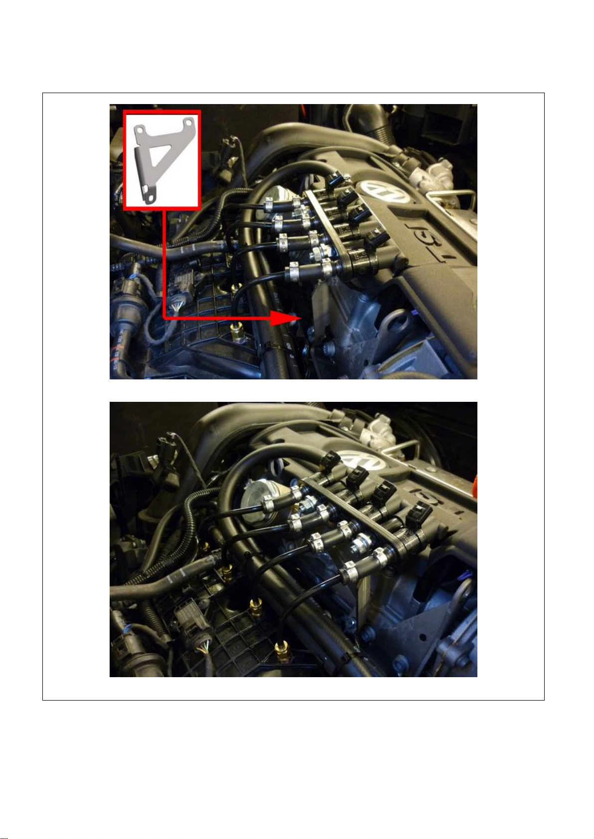
Mounting the VSI injector rail
Mount the bracket to the engine, mount the injector rail to the bracket.
PAGE 12
076/2613400
Copyright © Prins Autogassystemen B.V. 2014
VW Tiguan 1.4 CAXA / CAXC
12
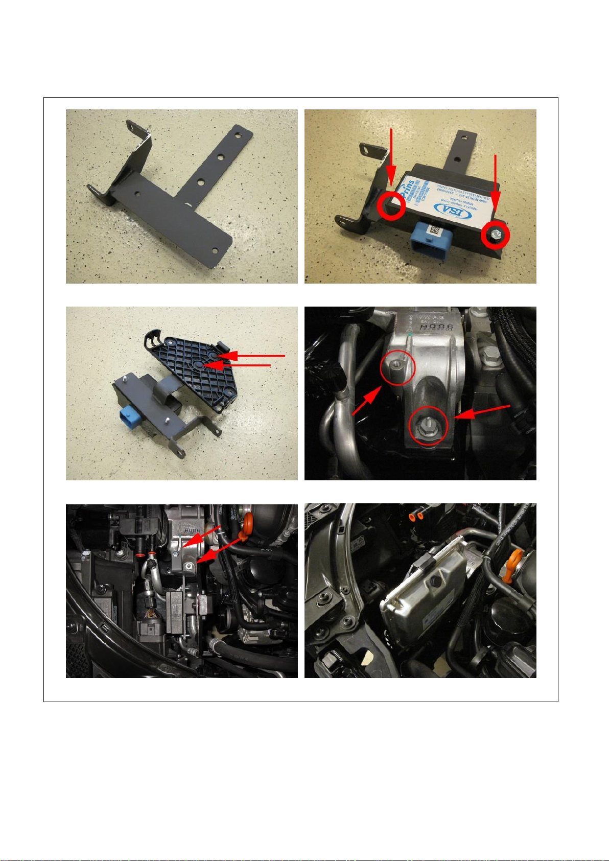
Mounting the Keihin filter unit
Mount filter unit on bracket
Mount filter unit bracket on original engine support. Mount LPG hose from reducer to filter with protection.
Mount 11mm LPG hose from filter to injector rail.

PAGE 13
076/2613400
Copyright © Prins Autogassystemen B.V. 2014
VW Tiguan 1.4 CAXA / CAXC
13
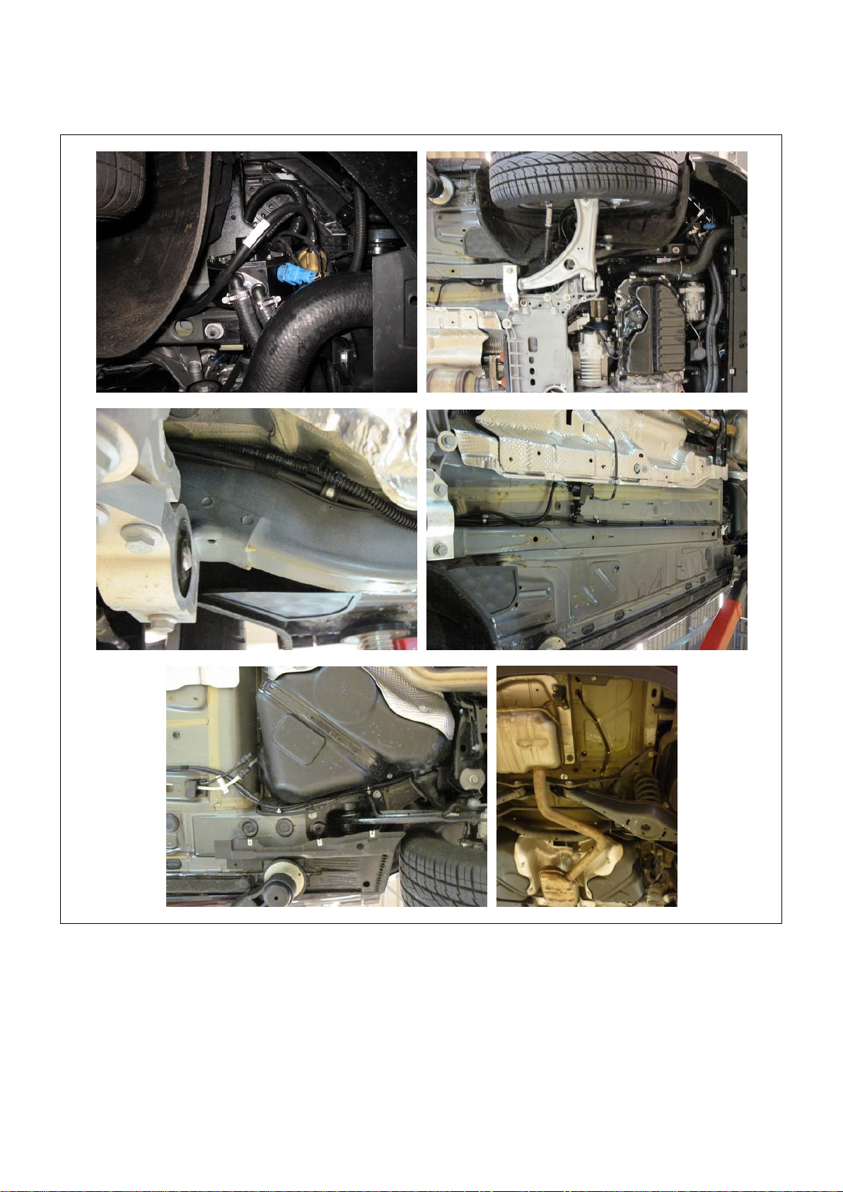
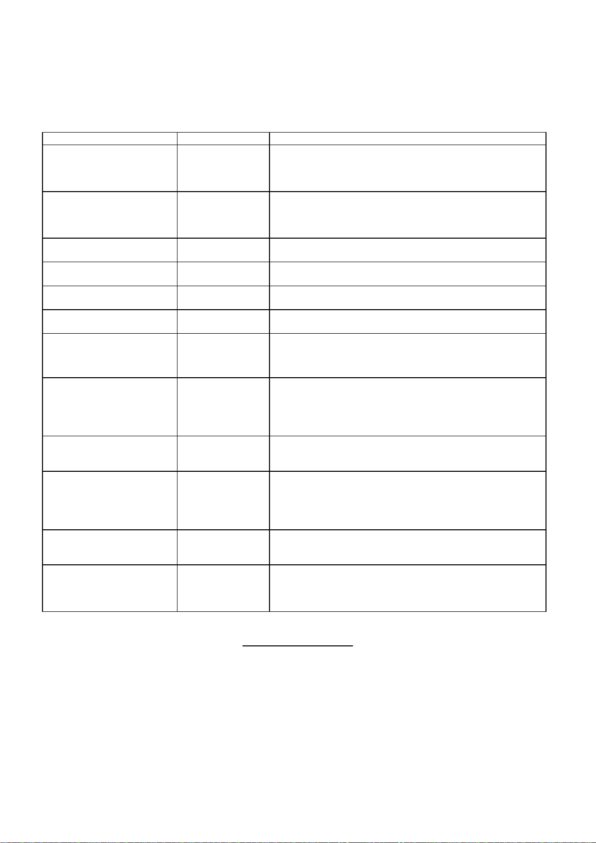
LPG hoses
Hose
(Ø..mm)
From component
To component
Hose length
(cm)
16
Reducer
Keihin filter unit
50
11
Keihin filter unit
VSI injector rail
105
5
Reducer overpressure
Y-piece
13
5
Reducer MAP connection
Y-piece
16
5
Y-piece
Inlet manifold coupling ( vacuum )
148
6
VSI injector 1
Nylon hose cyl.1
5
6
VSI injector 2
Nylon hose cyl.2
5
6
VSI injector 3
Nylon hose cyl.3
5
6
VSI injector 4
Nylon hose cyl.4
5
General info.
In Case of a Keihin filter : only use two M6x10mm bolts with spring washers.
Cut the LPG hoses on length.
Cut the nylon hoses on length, make sure that the inlet of the nylon hose faces the injector outlet.
Please observe that there is no damage or fouling to the hoses.
PAGE 14
076/2613400
Copyright © Prins Autogassystemen B.V. 2014
VW Tiguan 1.4 CAXA / CAXC
14
LPG piping
PAGE 15
076/2613400
Copyright © Prins Autogassystemen B.V. 2014
VW Tiguan 1.4 CAXA / CAXC
15
Mounting the AFC & Injection module
Mount injection module on bracket with 2x M6 bolts and spring washers.
Mount plastic AFC clip with quick-clips to bracket. Mount bracket to engine support.
Mount bracket to engine support. Mount AFC onto AFC clip.
PAGE 16
076/2613400
Copyright © Prins Autogassystemen B.V. 2014
VW Tiguan 1.4 CAXA / CAXC
16
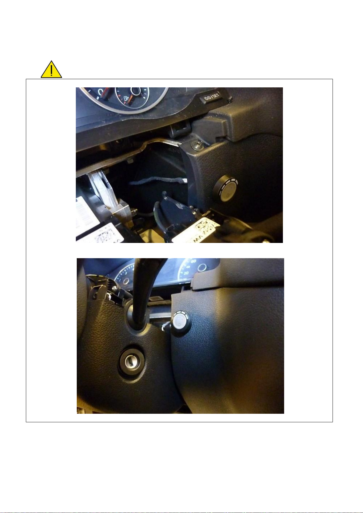
Mounting the fuel selection switch
When mounting the switch, only push on its sides.
Pushing the switch in the centre may result in damage to the switch.
See general manual for programming the selection switch
Drill hole Ø8,3mm
PAGE 17
076/2613400
Copyright © Prins Autogassystemen B.V. 2014
VW Tiguan 1.4 CAXA / CAXC
17
Electrical connections
Check and measure the wiring in case of changes in the cars wiring colours.
Insulate not used wires.
Wire number / code
Wire colour
Connection
32 Ground sense
1 Ground battery
Brown
Brown
Connect to the '–' of the battery; use a ring terminal or
solder:
Wire colour : Black
Wire location : - (ground) battery
4 +12V Battery
Red
Do not place the fuse in the holder before having completed
the installation of the LPG system.
Wire colour : Red
Wire location : + Battery
98 98 G INJ OUT 1
106 106 G + INJ 1
White - yellow
red
Connector VSI-injector to cylinder 1.
Timing belt side
99 99 G INJ OUT 2
107 107 G + INJ 2
Green - yellow
red
Connector VSI-injector to cylinder 2.
100 100 G INJ OUT 3
108 108 G + INJ 3
Pink - yellow
red
Connector VSI-injector to cylinder 3.
82 82 G INJ OUT 4
90 90 G + INJ 4
Blue - yellow
red
Connector VSI-injector to cylinder 4.
27 +5V Sensor
37 C ground
18 AD1
Red –blue (not used)
Brown - black (not used)
Blue - white
For measuring the inlet manifold pressure (MAP).
Wire colour : Yellow - blue
Wire location : Petrol ECU, connector T60, pin 55
17 AD2
25 DAC1
Blue –green
Green - white
High pressure petrol sensor signal interruption.
Sensor side.
ECU side.
Wire colour : Grey - blue
Wire location : Petrol ECU, connector T60, pin 40
63 Ground shift
Blue –orange
Make a connection to ground high pressure petrol sensor.
Wire colour : Brown - blue
Wire location : Petrol ECU, connector T60, pin 13
112 (+ Petrol Injectors)
+ Ignition
Red - grey
Make a connection to ignition + / contact +.
Do not place the fuse in the holder before having completed
the installation of the LPG system.
Wire colour : Grey or grey - black
Wire location : Petrol ECU, connector T94, pin 87
8 RPM engine speed
Purple - white
For measuring the engine speed.
Wire colour : Green - red
Wire location : Petrol ECU, connector T60, pin 36
40 Wake-up
Grey-red
High pressure petrol sensor 5Volt supply / car wake-up
Wire colour : red-blue
Wire location : Petrol ECU, connector T60, pin 29
Insulate not used wires
PAGE 18
076/2613400
Copyright © Prins Autogassystemen B.V. 2014
VW Tiguan 1.4 CAXA / CAXC
18
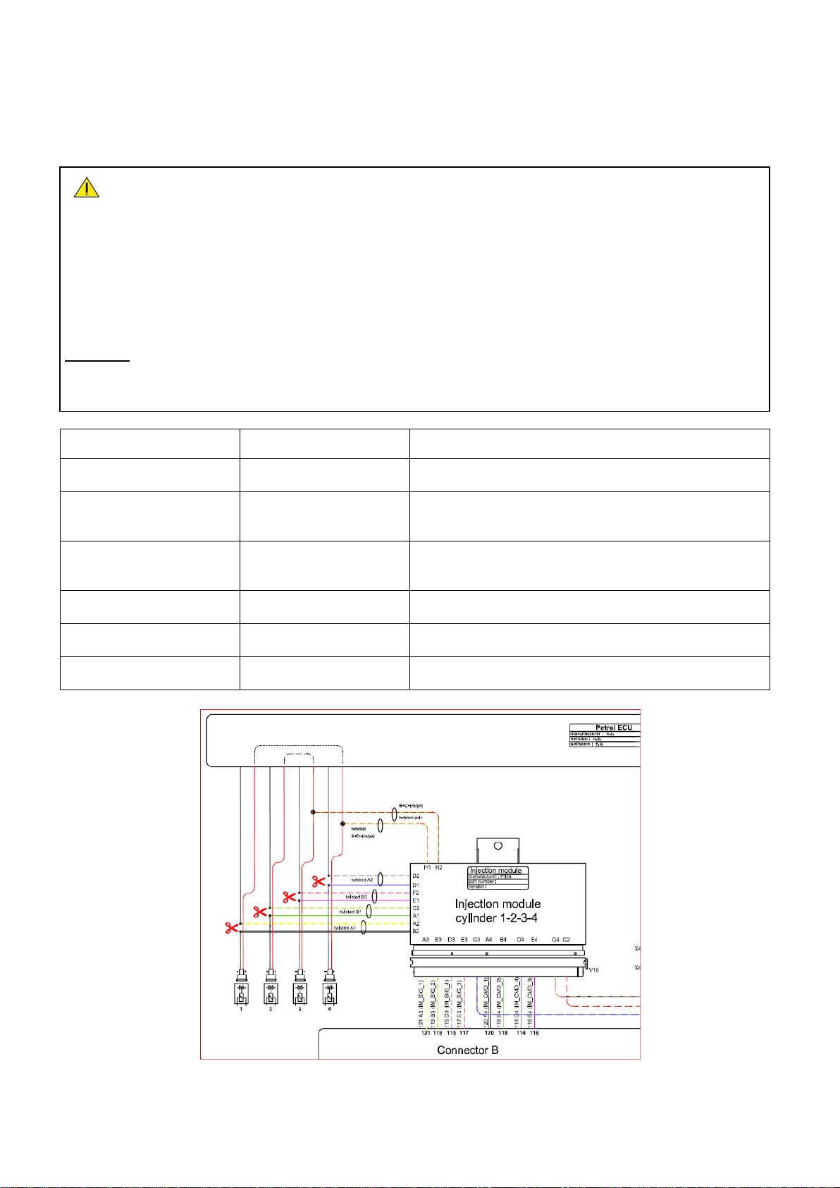
Electrical connections
Check and measure the wiring in case of changes in the cars wiring colours.
For measuring the petrol injectors :
Interrupt each petrol injector control wire (injector min)
Each VSI wire has a petrol injector / cylinder number printed on the wire, connect this wire to the corresponding
petrol injector / cylinder.
Connect the bicoloured VSI measuring wire to the ecu side, ( wire code: ecu-lo ).
Connect the corresponding full coloured VSI wire to the petrol injector side ( wire code: inj-lo ).
See diagrams: Installation manual general part 1 / 2.
Attention:
Each bicoloured measuring wire corresponds to a specific LPG injector and petrol injector / cylinder
number. Do not interchange the wires.
VSI measure wire nr. :
Full coloured / Bicoloured
Module position
Interrupt petrol injector wire
VSI wire inj / ecu 1
Petrol injector cyl. 1
white / white-yellow
B2 / A2
Colour : Brown - black
Location : Petrol ECU, connector T60, pin 33
VSI wire inj / ecu 2
Petrol injector cyl. 2
green / green-yellow
A1 / C2
Colour : Brown - white
Location : Petrol ECU, T60, pin 49 MED 17.5.5
Location : Petrol ECU, T60, pin 34 MED 17.5.20
VSI wire inj / ecu 3
Petrol injector cyl. 3
pink / pink-yellow
E1 / F2
Colour : Brown - purple
Location : Petrol ECU, T60, pin 34 MED 17.5.5
Location : Petrol ECU, T60, pin 49 MED 17.5.20
VSI wire inj / ecu 4
Petrol injector cyl. 4
blue / blue-yellow
D1 / D2
Colour : Brown - grey
Location : Petrol ECU, connector T60, pin 48
Module wire pos. H1
ECU HIGH A ( cil. 1-4 )
red-yellow
H1
Colour : Red –black
Location : Petrol ECU, connector T60, pin 31
Module wire pos. H2
ECU HIGH B ( cil. 2-3 )
red-green
H2
Colour : Red - white
Location : Petrol ECU, connector T60, pin 32
PAGE 19
076/2613400
Copyright © Prins Autogassystemen B.V. 2014
VW Tiguan 1.4 CAXA / CAXC
19
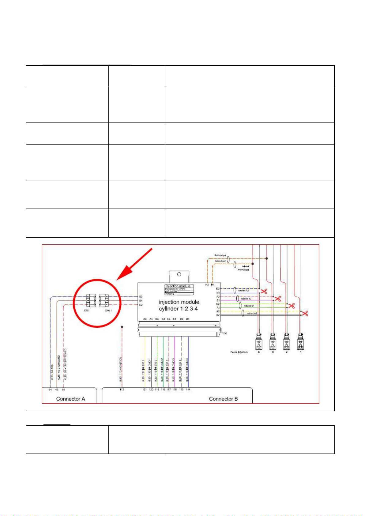
Electrical connections
Connectors from wiring loom
2-pole blue connector
15 T-ECT
34 Ground T-ECT
Grey
Brown - black
For measuring the engine coolant temperature ( Tect ).
Connect the connector to the reducer temperature sensor.
4-pole connector
35 Ground Psys
14 T-Gas
9 +5 Volt sensor
16 Psys
Brown - black
Grey
Red - blue
green
For measuring gas pressure and gas temperature.
Connect the connector to the filter unit sensor.
2-pole connector
24 +12V reducer lock-off
31 C Ground
Yellow - green
Brown - black
Connect the connector to the reducer lock-off valve.
4-pole connector
46 Service TxD
65 Service RxD
68 Ground PDT
Grey
Grey
Brown - black
Diagnose connector.
Tank wiring loom
2 +12V Tank relay
12 Tank level IN
26 Ground tank relay
red
blue
black
Connect to the tank lock-off.
Connect the tank level gauge.
Connect to the tank lock-off.
Wiring loom link
45 C ground
58 +12V switched
64 AD5
Brown –black
Red –white
Blue - grey
Connection from AFC connector A to connector B
Optional:
3-pole connector
11 + manometer
12 tank level in
33 ground manometer
red
blue
brown
Cut off connector and insulate wires
Table of contents
Other Prins Automobile Accessories manuals


Popular Automobile Accessories manuals by other brands


Thule
Thule 1527 instructions

Rhino-Rack
Rhino-Rack RLCP05 installation manual

Yakima
Yakima K1149 instructions

Westfalia Automotive
Westfalia Automotive 321 454 300 107 Installation and operating manual

Whelen Engineering Company
Whelen Engineering Company SA315 installation guide

Ratio Electric
Ratio Electric HOME BOX SMART manual