Prins Tiger User manual


User Manual Prins Tiger
Prins Maasdijk, October-2013
2
C
CO
ON
NT
TE
EN
NT
TS
S
1.
FOREWORD ............................................................................................... 3
2.
GENERAL SAFETY REGULATIONS..................................................................... 4
3.
SUMMARY OF COMPONENTS .......................................................................... 6
3.1
Main components ...................................................................................................... 6
3.2
Driving controls and instrument panel ............................................................................ 7
3.3
Switches and levers .................................................................................................. 12
3.4
Body components.................................................................................................... 20
3.5
LPG-version............................................................................................................ 24
4.
PRE-OPERATION CHECK .............................................................................. 29
5.
WEEKLY MAINTENANCE.............................................................................. 36
6.
SELF-SERVICING ........................................................................................ 39
7.
PERIODIC MAINTENANCE ............................................................................ 44
7.1
Periodic replacement table......................................................................................... 44
7.2
Periodic maintenance table ........................................................................................ 45
8.
SERVICE DATA.......................................................................................... 50
9.
ENGINE SPECIFICATIONS ............................................................................. 52
10.
WHEELS AND TIRES .................................................................................... 52
10.1
Tire air pressure ...................................................................................................... 52
10.2
Overview wheels and tires ......................................................................................... 52

User Manual Prins Tiger Foreword
3
Prins Maasdijk, October-2013
1
1.
.
F
FO
OR
RE
EW
WO
OR
RD
D
As manufacturer, we thank you for purchasing this Prins Tiger Forklift truck.
For your safety, please obey all safety guidelines as set out in this manual. To obtain a long and
trouble free operation from your forklift keep up regular servicing and read this manual thoroughly
before you start to work with it. Make sure other users of the truck read the manual as well.
Keep this manual, after poring it over, on a place where you can find it easily back, so that you always
have the information at one’s disposal concerning maintenance, defects and the like.
When you want to order some parts, or you have questions/remarks about your forklift truck, please
contact Prins Maasdijk. Please: always be sure you know your Service number and Serial number,
mentioned on the tag plates in the left and right upper corner of the steering column. Keep it always
nearby when you call us.
We wish you much success with your new forklift truck.
Prins Maasdijk

User Manual Prins Tiger General Safety Regulations
Prins Maasdijk, October-2013
4
2
2.
.
G
GE
EN
NE
ER
RA
AL
L
S
SA
AF
FE
ET
TY
Y
R
RE
EG
GU
UL
LA
AT
TI
IO
ON
NS
S
Accidents can occur if the safety regulations are disregarded, insufficient care is taken during
maintenance or when operating the machine. You must be aware of the risks entailed in certain
actions. This manual describes potentially hazardous situations and the measures to be taken during
operation and maintenance.
It is impossible for the manufacturer to foresee every potentially hazardous situation, which may lead
to injuries or damage. The user must ensure the safety of all actions, procedures or the use of any
tools that are not recommended by the manufacturer. Always use original spare parts.
For your and other people’s safety:
Never load the forklift truck above the maximum stipulated weight.
Always check the loading diagram on the bonnet.
The lifting capacity is halved when the load rests on only one fork. Avoid this as much as possible.
Keep the load as close to the ground as possible when driving with a loaded machine. Never drive
at top speed in this situation.
Keep the speed as low as possible when driving with an elevated load and keep track of the
maximum clearance height.
ALWAYS carry out the necessary preventive inspections and regular maintenance. Never start
working with the machine unless it has been thoroughly checked. Pay particular attention to the
tires, battery, brakes, steering gear, fuel system, and electrical components.
Do not refuel while the engine is running. No smoking is allowed during refueling or changing /
adding oil and fire and sparks must be prevented. Explosive gases are released during refueling.
Carefully remove any spilt liquids after refueling or changing / adding oil.
Before changing or adding oil, the machine must be checked for oil stains. Try to find out where
they come from. If they are caused by a technical failure, first repair the failure before continuing
working with the truck.
When leaving the machine, ensure that the handbrake is engaged and that the gears are in
neutral.
A wrong sitting position can cause accidents. Always adjust the chair so that you can properly
operate the levers and have a good sight.
Never work with a truck without a safety guard or safety bracket (which are standard supply).
Always wear you seat belts when operating the forklift truck.
Operate at a speed that gives you positive control of the truck. High speeds can be very
dangerous. Also sudden brakes, accelerations, or turns can cause dangerous situations.
If you have to drive at locations with little clearance height, take the following things into account:
oAlways check if there is enough clearance above and beside the truck.
oKeep all parts of the body inside the safety guard, keep your hands on the steering wheel and
keep your feet on the pedals.
oPay attention to where you drive
Gently operate the levers. This increases the life span of the truck and is much safer.

User Manual Prins Tiger General Safety Regulations
5
Prins Maasdijk, October-2013
Never walk under an elevated load. This is extremely dangerous.
Never carry a person on the forks or on the truck.
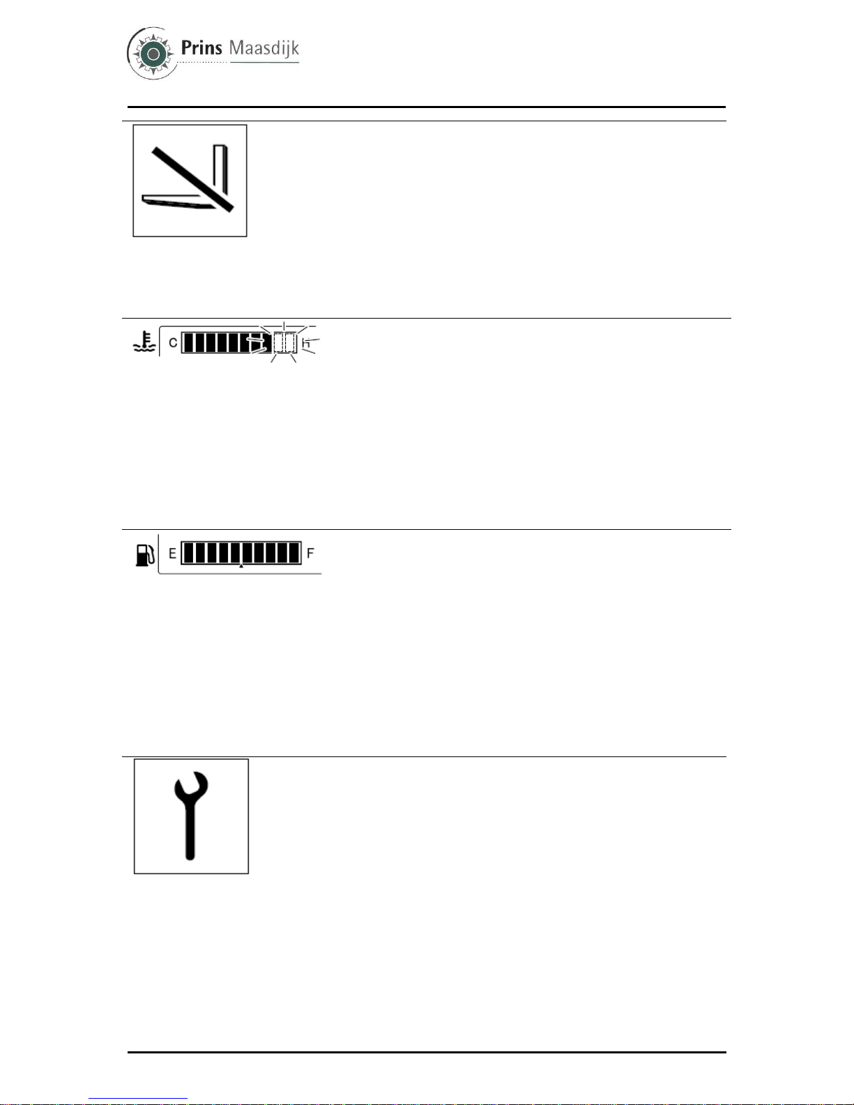
When lowering the forks, make sure the forks are horizontal or tilted a bit backwards. Never lower
the forks when they are tilted forwards.
The state of the machine can be checked by many factors. Any changes of sound, vibrations, or
reactions on the levers can indicate failures. If you suspect a failure, immediately pull over the
truck and stop the engine. Check for causes and take the necessary actions.
Table 2.1 | Safety symbols
Follow the instructions
for use and safety
Wear safety glasses
and protective clothing
Smoking and open
flames prohibited
Electrolyte is very
corrosive
Connectors are live,
avoid contact
Areas where batteries
are stored or charged
must be sufficiently
ventilated
Danger of explosions,
avoid short circuits
User Manual Prins Tiger Summary of components
Prins Maasdijk, October-2013
6
3
3.
.
S
SU
UM
MM
MA
AR
RY
Y
O
OF
F
C
CO
OM
MP
PO
ON
NE
EN
NT
TS
S
3.1
Main components
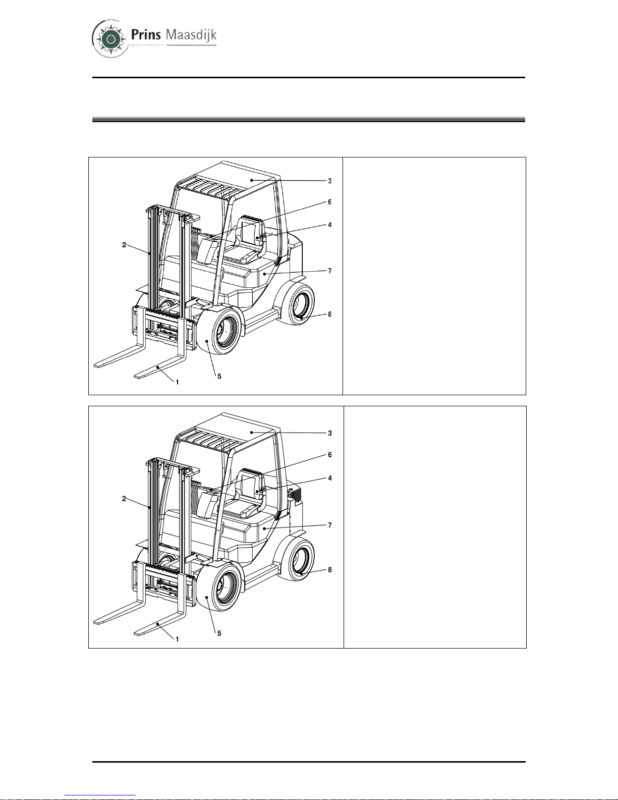
Tiger L
1 – Forks
2 – Mast
3 – Overhead guard
4 – Operator’s seat
5 – Front wheel
6 – Steering wheel
7 – Engine hood
8 – Rear (steering) wheel
Tiger XL
1 – Forks
2 – Mast
3 – Overhead guard
4 – Operator’s seat
5 – Front wheel
6 – Steering wheel
7 – Engine hood
8 – Rear (steering) wheel

User Manual Prins Tiger Summary of components
7
Prins Maasdijk, October-2013
Tiger XXL
1 – Forks
2 – Mast
3 – Overhead guard
4 – Operator’s seat
5 – Front wheel
6 – Steering wheel
7 – Engine hood
8 – Rear (steering) wheel
3.2
Driving controls and instrument panel
Driving controls
1 – Control lever
2 – Steering wheel
3 – Horn button
4 – Light control and turn signal switch
5 – Lift lever
6 – Tilt lever
7 – Side shifter lever
8 – Accumulator switch (option)
9 – Accelerator pedal
10 – Brake pedal
11 – Ignition switch
12 – Parking brake release lever
13 – Inching- en brake pedal
14 – Tilt steering adjust lever
15 – Parking brake pedal
Diesel engine models
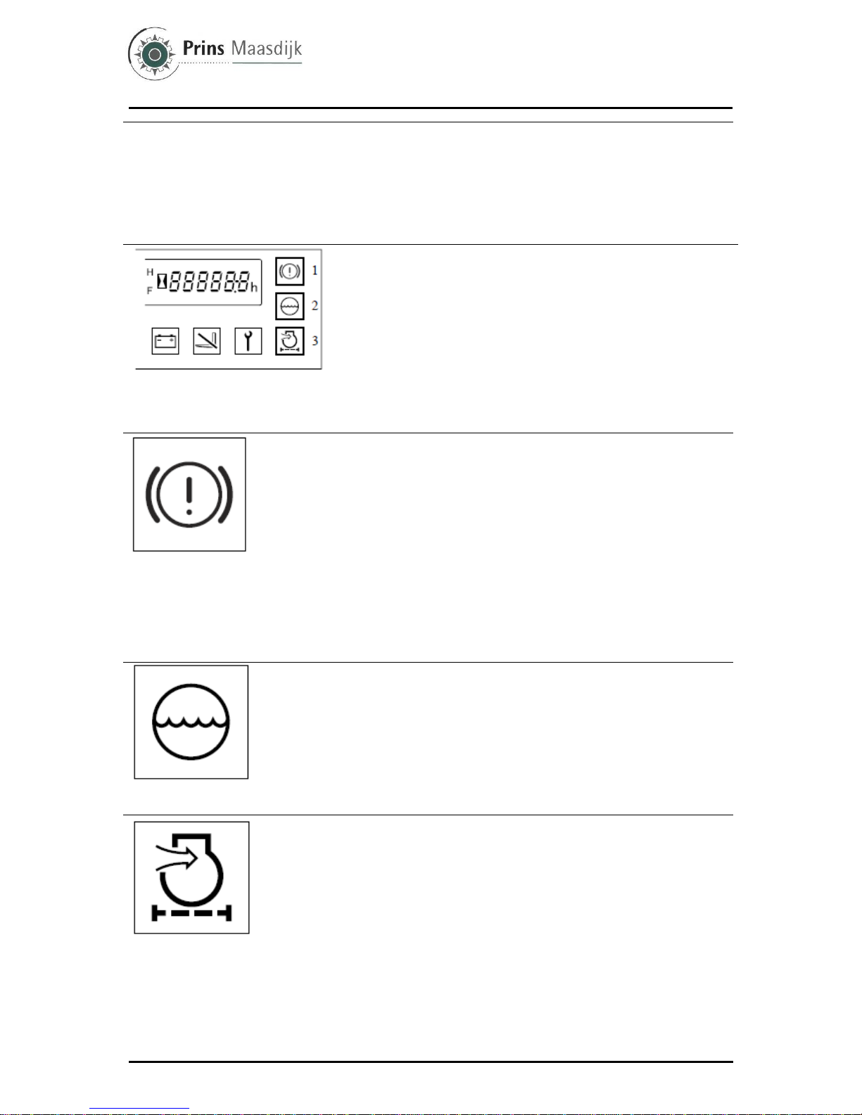
General screen
1 - Water temperature gauge
2 - Hour meter
3 - Brake warning lamp
(OK monitor: option)
4 - Fuel gauge (Diesel and Gasoline/LPG
engine models)
5 - Sedimenter warning lamp
(Diesel engine models)

User Manual Prins Tiger Summary of components
Prins Maasdijk, October-2013
8
LPG engine models
General screen (continuation)
6 - Glow indicator lamp
(Diesel engine models)
Engine check lamp (LPG and
Gasoline/LPG engine models)
7 - Engine oil pressure warning lamp
8 - Charge warning lamp
9 - OPS lamp
10 - Diagnosis lamp
11 - Air cleaner warning lamp
(OK monitor: option)
12 - Coolant level warning lamp
(OK monitor: option)
Gasoline/LPG engine models
Start
Warning lamp check method
Please check if all warning lamps come on when the ignition switch is turned
to ON.
Note:
Use the light control switch to check the meter-lighting lamp.
►Caution!
• The glow indicator lamp (Diesel engine models) is only on for 2 seconds
when the engine coolant temperature exceeds 50°C.
• If a lamp does not light up, contact Prins Maasdijk and request an
inspection.
Hour meter also serving as diagnosis indicator
The hour meter operates when the ignition switch is turned to ON. It indicates
the total number of vehicle operating hours. The unit of the right most digit is
1/10 hour.
Please use this meter for the timing of periodic maintenance and recording
the operation hours.
When an abnormality occurs to the vehicle (diagnosis lamp lights up or
blinks) the error code and hour meter will be alternately displayed.
►Caution!
• Should an error code be displayed, park the vehicle in a safe location and
contact your dealer to request an inspection.

User Manual Prins Tiger Summary of components
9
Prins Maasdijk, October-2013
Engine oil pressure warning lamp
Comes on to indicate low engine oil pressure while the engine is running.
1. If normal, the lamp comes on when the ignition switch is turned to ON and
goes off when the engine starts.
2. If the lamp comes on while the engine is running, either the engine oil is
low or the lubrication system is faulty. Stop the operation immediately and ask
Prins Maasdijk for inspection and repair.
Note:
The “engine oil pressure warning lamp” does not indicate the oil level. Check
the oil level using the oil level gauge before starting work.
Sedimenter warning lamp (Diesel engine models)
The sedimenter is a device for separating water from the fuel.
1. The warning lamp comes on to indicate water in the sedimenter exceeds
the predetermined level while the engine is running.
2. If normal, the lamp comes on when the ignition switch is turned to ON and
goes off when the engine starts.
3. If the lamp comes on while the engine is running, drain water immediately.
(See the self service section for the draining instructions.)
►Caution!
• Continued operation with the lamp on may cause seizure of the injection
pump and pump damage. If the warning lamp lights up, always make sure to
drain the water.
Glow indicator lamp (Diesel engine models)
Indicates heating of glow plugs.
When the ignition switch is turned to ON, the lamp comes on and glow plug
heating begins. The lamp goes off automatically when glow plug heating is
complete. The engine will start easily once the glow plugs are heated.
Note:
The glow indicator lamp is on for 2 seconds when the engine coolant
temperature exceeds 50°C.
Engine check lamp (LPG and Gasoline/LPG engine models)
When an error occurs to the engine controller, the display will light up to
inform the operator. When condition is normal, the lamp will light up when the
ignition switch is turned to the ON position. The lamp will turn off when the
engine is started.
►Caution!
• If the engine check lamp lights up during operation, stop operations and
park the vehicle in a safe location, ask your dealer to perform an inspection.
Charge warning lamp
1. This lamp comes on to indicate an abnormality in the charging system
while the engine is running.
2. If normal, the lamp comes on when the ignition switch is turned to ON and
goes off when the engine starts.
3. If the lamp comes on while the engine is running, stop immediately, park
the vehicle in a safe location, stop the engine and after the engine has cooled
down inspect the fan belt for cuts or looseness, adjust it, and restart the
engine.
If lamp does not go off, the electrical system may be faulty.
Please ask Prins Maasdijk immediately for inspection and repair.
User Manual Prins Tiger Summary of components
Prins Maasdijk, October-2013
10
OPS lamp
If the operator leaves the seat, the OPS lamp will light up, indicating that the
OPS System is operating. (If the operator returns to normal seating position
within 2 seconds, loading can be continued.) In such a situation, return the
control lever and lift lever to the neutral position, then sit on the seat again.
►Caution!
In the following cases, a malfunction may have occurred to the OPS System.
Park the vehicle in a safe location and contact Prins Maasdijk to request an
inspection.
• If the operator leaves the seat, the OPS lamp does not light up.
• Even when the operator re-seats, the OPS lamp does not turn off.
Water temperature gauge
Indicates the temperature of the engine coolant.
1. This gauge functions with the ignition switch ON, and displays
the coolant water temperature from left to right in a 10-stage
gradation scale.
2. The operator will be notified when the water temperature is
115ºC or over (above 8th stage), as the final two stages at far
right begin blinking. Again, when the engine protection function
activates (for vehicles with Multifunction display: OPT), the entire
gauge will start blinking to inform the operator.
3. Temporary overheating may be caused by coolant leakage, low
engine coolant level, loosened fan belt, or other problem in the
cooling system. Contact Prins Maasdijk to request an inspection.
Fuel gauge (Diesel and Gasoline/LPG engine models)
Indicates the amount of remaining fuel in the fuel tank in terms of
a 10-stage gradation scale. The operator will be notified that
remaining fuel level is low when the two stages at far left start
blinking. It takes some time for the indication to be stabilized after
refueling and the ignition switch is turned to ON.
Note:
• If the operating area is not level, attention must be paid because
the correct level may not be indicated.
• When the gauge begins blinking, refuel as soon as possible.
In case of diesel engine, be sure to refuel it before it runs out
because when this occurs it becomes necessary to bleed air from
the fuel supply system.
Diagnosis lamp
If an abnormality is registered by the OPS or mini lever, the
respective lamps will light up or blink to inform the operator and
the diagnosis error code will be displayed in the hour meter
display area. If the following conditions occur to the lamp, there
may be a system abnormality. Contact your dealer to request an
inspection.
• The lamp does not light up when the ignition switch is turned
ON.
• The lamp lights up when ignition switch is turned ON and stays
ON.
• The lamp blinks during ignition switch is turned ON.
►Caution!
• Continuing to use the vehicle while the diagnosis lamp is
lighted or blinking may lead to a breakdown. When the lamp
lights up or blinks, halt all operations and park the vehicle in a
safe location. Contact Prins Maasdijk to request an inspection.
User Manual Prins Tiger Summary of components
11
Prins Maasdijk, October-2013
(In the case of diesel engine vehicles, the diagnosis lamp may
light up during engine warm-up after a cold-start, but does not
indicate an abnormality.)
• If the operator remains seated for a long period with the ignition
switch turned to OFF, the next time the ignition switch is turned
to ON, the diagnosis lamp may start blinking. If this occurs, leave
the seat. The diagnosis lamp will then turn off.
1 - Brake warning lamp
2 - Coolant level warning lamp
3 - Air cleaner warning lamp
OK monitor (option)
Senses the engine coolant level, brake fluid level, clogged air
cleaner element and parking brake status. The lamp comes on to
indicate a problem. If the lamp comes on when the ignition switch
is on (irrespective of the engine speed), the corresponding part
may be abnormal. Contact Prins Maasdijk to request an
inspection.
►Caution!
• Always perform pre-operation checks. Do not rely on the OK
monitor, even if it is not lit.
Brake warning lamp
When the parking brake is engaged or brake liquid is low, the warning lamp
will light up to notify the operator.
1. The warning lamp will light up when the parking brake is engaged. After
disengaging the brake to operate the vehicle, check to make sure the warning
lamp has turned off.
2. The lamp will light up to notify the operator when the brake oil is low.
►Caution!
• If the warning lamp does not turn off when the parking brake is disengaged,
the brake fluid may be low. Inspect the brake fluid level and replenish it if
necessary.
• If the warning lamp remains a lighted even if the brake fluid level is
sufficient, contact Prins Maasdijk to request an inspection.
Coolant level warning lamp
1. When the coolant level of the radiator reserve tank becomes low, the
indicator lamp will light up to notify the operator.
2. If the lamp lights up while the engine is running, this may indicate a
deficiency in coolant. Stop the engine and inspect the coolant level in the
radiator reserve tank and the radiator. Before checking coolant level in the
radiator wait for it to cool as it maybe under pressure when hot.
3. Even if the coolant level warning lamp is not lighted, always inspect the
coolant level before starting operations.
Air cleaner warning lamp
1. This lamp comes on when the air cleaner element gets clogged while
engine is running.
2. If normal, the lamp comes on when the ignition switch is turned to ON and
goes off when the engine starts.
3. If the lamp comes on while the engine is running, stop operations and park
the vehicle in a safe location, stop the engine and clean the element and dust
cup. For the cleaning method, refer to the Weekly Inspection Section in this
manual.
User Manual Prins Tiger Summary of components
Prins Maasdijk, October-2013
12
3.3
Switches and levers
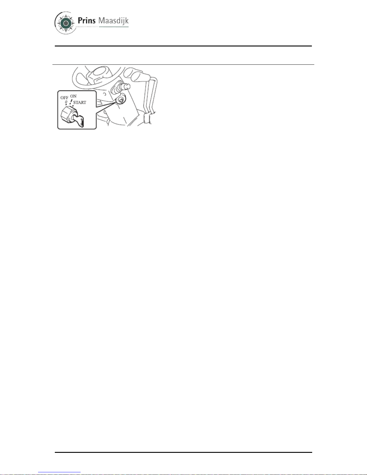
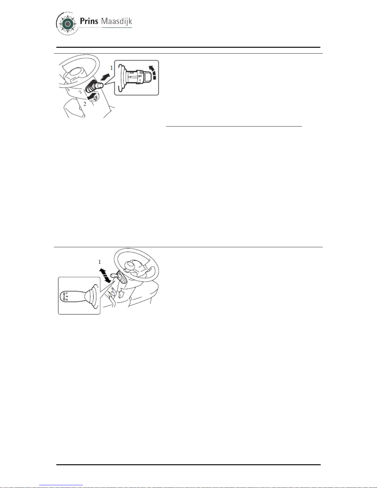
Ignition switch
O [OFF] – Engine stop position. Key insertion and
withdrawal are performed in this position.
I [ON] – Engine operation position. Located one position
clockwise from O [OFF] position.
The intake heater is preheated before starting in the
diesel models.
START – Engine, start position. Located one position
clockwise from the I [ON] position.
After the engine starts, release the key and it will return to
the I [ON] position automatically.
In the torque converter model, the engine does not start
unless the control lever is set in the neutral position.
►Caution!
• Never operate the ignition switch without First sitting on
the seat. Otherwise, the forklift could start to move
uncontrolled, causing an accident.
• When the OPS lamp is on, return each lever to the
neutral position and sit on the seat. Then confirm that the
lamp has gone off.
• Do not leave the switch in the [ON] position when the
engine is stopped. It may cause over discharge of the
battery.
• Do not turn the switch to the START position while the
engine is running.
• For the sake of safety it is recommended to always start
the engine of a vehicle with the transmission gear shift
lever shifted in the neutral position.
• Do not operate the starter motor for more than 30
seconds continuously. Return the switch to the [OFF]
position and wait at least 30 seconds prior to attempting
restart.
• In case of the anti-restart ignition switch (optionally
available), be sure to shift the switch to the [OFF] position
before attempting to start the engine again.
• With the ignition switch OFF (engine off), the forks will
not lower even if the lift lever is operated. However, if you
sit in the seat and turn on the ignition switch, you can
lower the forks. (Except mini lever models) Do not operate
the lift lever before getting on the vehicle and starting up
the engine. (key-off, lift locked)
• If the diagnosis lamp does not go off even when the
operator sits on the seat, the battery power may be low. In
such a case, do not drive the vehicle until the lamp goes
off, otherwise the vehicle may not operate correctly. If you
are obliged to drive the vehicle, do so with the utmost
care.
Also, stop driving and ask Prins Maasdijk for inspection if
the lamp does not go off 1-2 minutes after the engine
starts, or when you race the engine for a while. (For diesel
vehicles, the diagnosis lamp may be on for a while to
warm up the engine after cold starting. This is, however,
not an engine malfunction or failure.)
User Manual Prins Tiger Summary of components
13
Prins Maasdijk, October-2013
1 – Left turn
2 – Right turn
Integrated light and turn signal switch
This two-position switch serves as both a light switch and
turn signal switch.
Light control switch
Irrespective of an ignition switch position, this switch allows
you to turn on and off the lights.
This switch has two positions. With the switch at each
position, the light comes on as shown below.
Lamp name Step 1 Step 2
Head lamps − O
Side lamps, tail lamps (option) O O
Meter illumination lamp O O
►Caution!
• Do not keep lights such as head lights on for a long period
when the engine is stopped. It may cause over discharge of
the battery and make engine starting impossible.
Turn signal switch
Makes the turn signal lamps blink.
Left turn – Push forward
Right turn – Pull backward
The signal switch will operate when the ignition switch is
ON.
The turn signal lever returns automatically to the original
position after making a direction change.
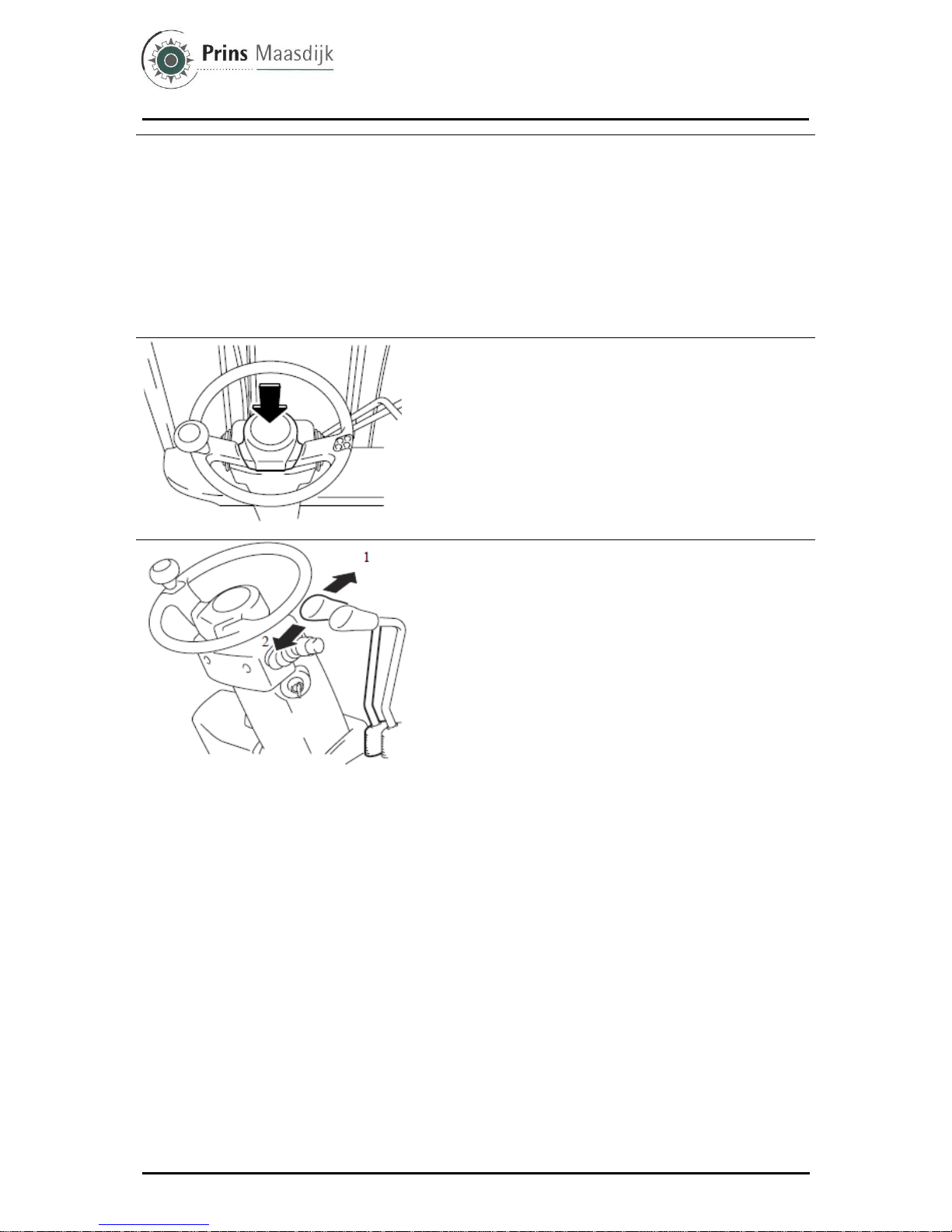
1 – Forward
2 – Reverse
Control lever
Lever for shifting between forward and reverse
Forward – Push forward
Reverse – Pull backward
The neutral position is halfway between the forward and
reverse position.
Note:
After the OPS System operates, return the accelerator
pedal to its fully released position and set the control lever
to the neutral position, and sit on the seat to restart driving.
(Even though the operator sits on the seat, driving is
impossible unless the control lever is in the neutral
position.)
►Caution!
• The engine cannot be started unless the control lever is in
the neutral position.
• Stop the vehicle before shifting between forward and
reverse direction.
Torque convertor interlock function (OPT)
If you switch the control lever direction to something other
than the current travel direction while moving at high speed,
this function electrically disengages the drive and sets the
torque converter to neutral. Once the speed drops below
the set speed while running in neutral, the travel direction is
automatically switched.
To change travel direction, operate the control lever after
travel speed is reduced sufficiently. Ask Prins Maasdijk for
changing speed setting.
User Manual Prins Tiger Summary of components
Prins Maasdijk, October-2013
14
►Caution!
• When the interlock has engaged, release the accelerator
pedal and use the brake pedal to reduce speed. After the
vehicle has stopped moving, slowly press the accelerator
pedal down to start moving again. Disengaging the interlock
while the accelerator pedal is pressed down could result in
wheel spin.
• Do not perform Forward or Backward operation on slopes.
If control lever is operated on a down slope, torque
converter interlock function may not operate correctly.
Horn button
Press the button in the center of the steering wheel to
sound the horn.
The horn will sound even when the ignition switch is OFF.
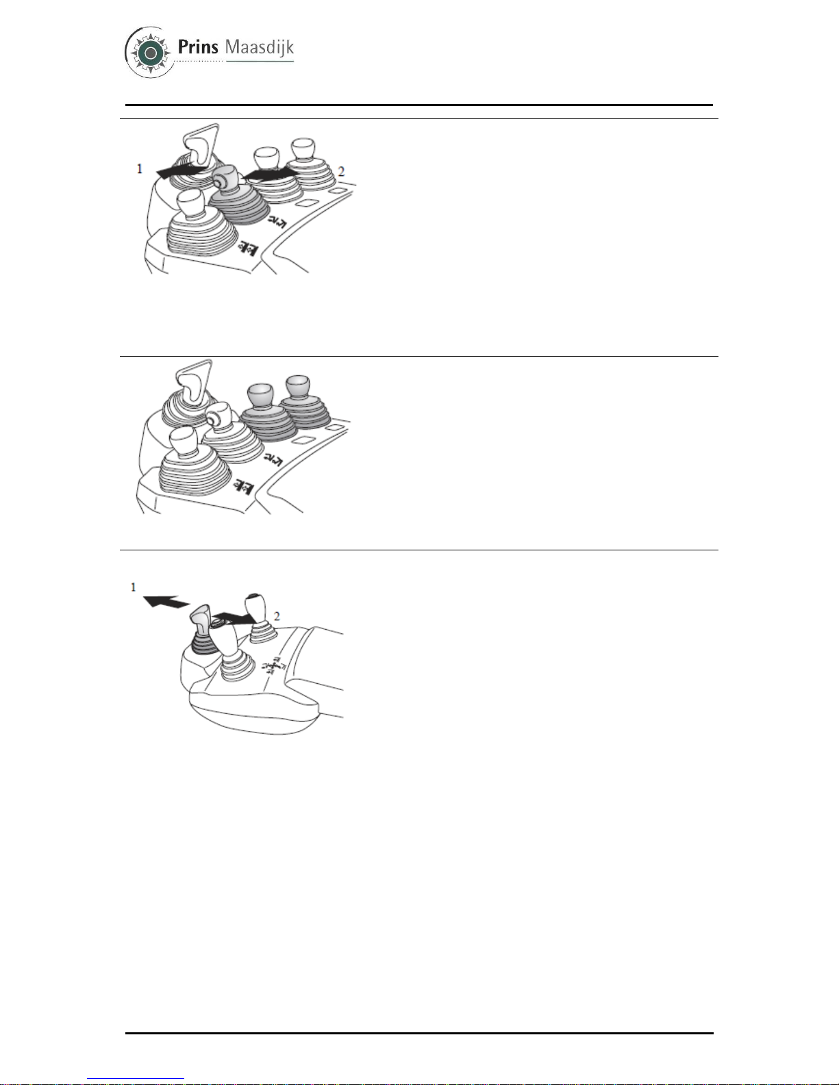
1 – Lower
2 – Raise
Lift lever
Raises and lowers the forks
Raise – Pull backward
Lower – Push forward
The lifting speed can be adjusted by how far the
accelerator pedal is depressed and how far the lever is
pull back.
The lowering speed can be adjusted only by how far the
lever is pushed forward.
►Caution!
• After the OPS System operates, return the accelerator
pedal to its fully released position and set the lift lever to
the neutral position, and sit on the seat to restart the
operation. (If you sit on the seat while raising the lift lever,
the forks will start to move 1 second later.)
• If you sit on the seat while lowering the lift lever, the
forks will not lower due to the return to neutral function.
• Always operate the lift lever while correctly seated.
• When the ignition switch is turned to OFF and lowering
the lift lever, the forks will not lower.
However, if the operator sits in the normal seated position
then the ignition switch is turned to ON, the forks will be
lower even if the engine is off. (Except mini-lever/joy stick
models)

User Manual Prins Tiger Summary of components
15
Prins Maasdijk, October-2013
1 – Lift lock release bolt
Key-lift interlock
When the ignition switch is OFF, the lift will not descend
even if the lift lever is lowered. However, if the operator
sits properly in the seat and turns the ignition switch
ON, the forks can be lowered even if the engine is off
(Except mini lever/joy stick models).
If the ignition switch cannot be turned ON for whatever
reason, loosen the manual lowering valve located on
the oil control valve beneath the toe board, and operate
the lift lever in the downward direction.
Once the forks have been lowered with the lift lock
release bolt, close and lock the valve.
1 – Forward tilting
2 – Backward tilting
Tilt lever
Tilts the mast forward and backward.
Forward – Push forward
Backward – Pull backward
The forward or backward tilting speed can be adjusted
by the degrees of accelerator pedal depression and
lever operation stroke.
►Caution!
• Insure the load-handling control levers are in their
neutral positions before returning to the operator's seat,
if not load-handling functions will start movement 1
second after operator returns to the seat.
• Always operate the tilt lever from a seated position.
• After the OPS System operates, return the accelerator
pedal to its fully released position and the tilt lever to the
neutral position, and sit on the seat to restart the
operation. (If the operator sits on the seat without
returning the load-handling control levers to their neutral
positions, load-handling functions will start movement 1
second after.)
1 – Shifting towards left
2 – Shifting towards right
Side shifter lever
Shifts the fork carriage on the left or on the right
Left – Push forward
Right – Pull backward
►Caution!
• Insure the load-handling control levers are in their
neutral positions before returning to the operator's seat,
if not load-handling functions will start movement 1
second after operator returns to the seat.
• Always operate the side shifter lever from a seated
position.
• After the OPS System operates, return the accelerator
pedal to its fully released position and the side shifter
lever to the neutral position, and sit on the seat to restart
the operation. (If the operator sits on the seat without
returning the load-handling control levers to their neutral
positions, load-handling functions will start movement 1
second after.)

User Manual Prins Tiger Summary of components
Prins Maasdijk, October-2013
16
1 – Forward
2 – Backward
Mini lever (option)
Control lever
Lever for shifting between forward and reverse
Forward – Push forward
Reverse – Pull backward
The speed of forward and backward traveling can be
adjusted by the extent of pressing the accelerator
pedal.
Note:
• Stop the vehicle before shifting between forward and
backward traveling.
• After the OPS System has been activated, return the
accelerator pedal and control lever to their neutral
positions and return to the seat before recommencing
operations.
• Always operate the control lever from a properly
seated position.
• Depending on the vehicle specifications, the position
of the control lever may vary.
1 – Lower
2 – Raise
1 – Lift lock release bolt
Lift lever
Raise and lower the forks for loading.
Raise – Pull backward
Lower – Push forward
Raising speed can be adjusted by the extent of
pressing the accelerator pedal and pulling the lift
lever.
Lowering speed can be adjusted by the extent of
pushing the lift lever.
Note:
• After the OPS System has been activated, return the
accelerator pedal and all of the levers to their neutral
positions and return to the seat before recommencing
operations.
• If you return to the seat while lowering the lift lever,
the forks will not descend due to the return to neutral
function.
• Always operate the lift lever from a properly seated
position.
• When the ignition switch is turned to OFF, the forks
will not descend even if the lift lever is lowered. (Key-
lift interlock)
• When the forks will not lower due to system
malfunction or other reasons, they can be lowered by
opening the lift lock release bolt.
• If you lower the forks by opening the lift lock release
bolt, close and lock the bolt.
User Manual Prins Tiger Summary of components
17
Prins Maasdijk, October-2013
1 – Forward tilting
2 – Backward tilting
Tilt lever
Tilt the mast forward and backward.
Forward – Push forward
Backward – Pull backward
Forward or backward tilting speed can be adjusted by the
extent of pressing the accelerator pedal and operating the
lever.
Note:
• After the OPS System has been activated, return the
accelerator pedal and all of the levers to their neutral
positions and return to the seat before recommencing
operations.
• Always operate the tilt lever from a properly seated
position.
Attachment lever
Operates the attachment.
Attachment speed can be adjusted by the extent of
pressing the accelerator pedal and operating the lever.
Note:
• After the OPS System has been activated, return the
accelerator pedal and all of the levers to their neutral
positions and return to the seat position before
recommencing operations.
• Always operate the attachment lever from a properly
seated position.
1 – Forward
2 – Backward
Joy stick (option)
Control lever
Lever for shifting between forward and reverse
Forward – Push forward
Reverse – Pull backward
The speed of forward and backward traveling can be
adjusted by the extent of pressing the accelerator pedal.
Note:
• Stop the vehicle before shifting between forward and
backward traveling.
• After the OPS System has been activated, return the
accelerator pedal and control lever to their neutral positions
and return to the seat before recommencing operations.
• Always operate the control lever from a properly seated
position.
• Depending on the vehicle specifications, the position of the
control lever may vary.
User Manual Prins Tiger Summary of components
Prins Maasdijk, October-2013
18
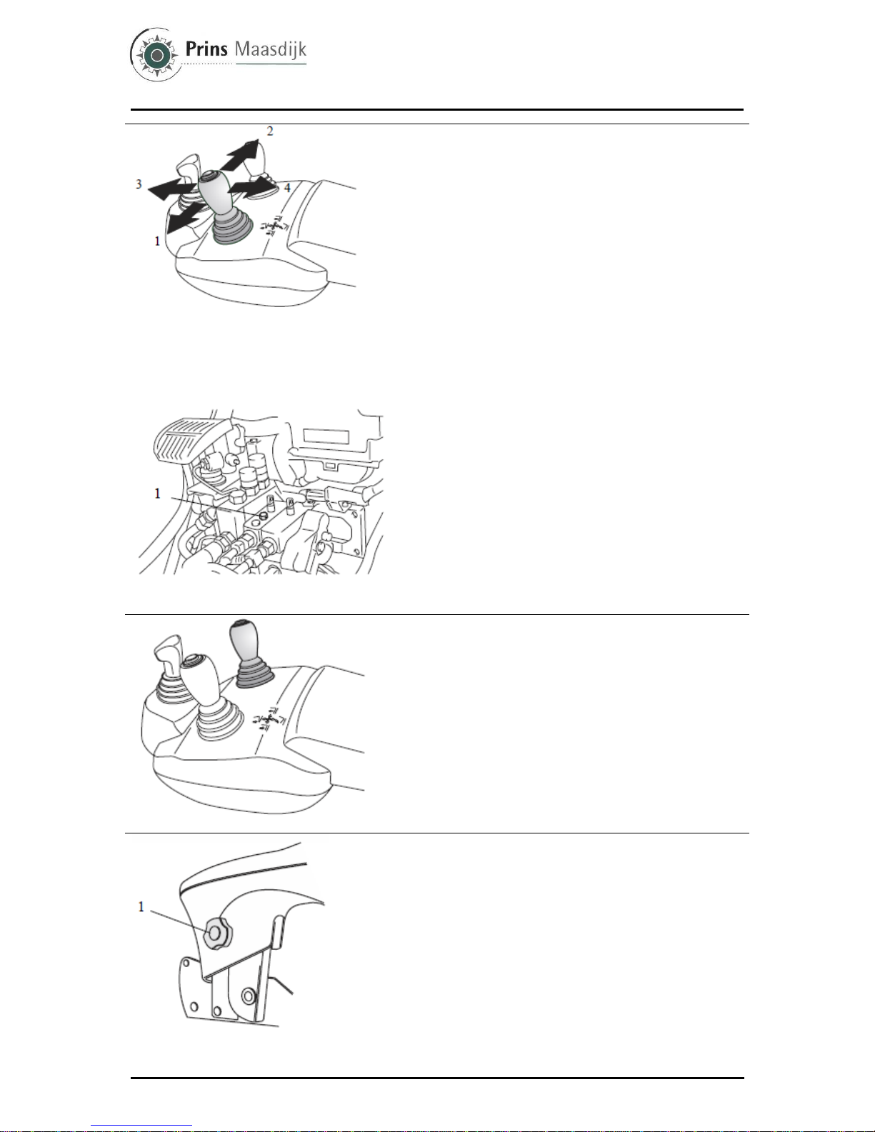
1 – Lower
2 – Raising
3 – Forward tilting
4 – Backward tilting
1 – Lift lock release bolt
Lift tilt lever
Operation to the left and right controls lift, and forward
and backward operation control tilt.
Raising – Operate the lever to the right
Lowering – Operate the lever to the left
Forward-tilt – Operate the lever forward
Backward-tilt – Operate the lever backward
Raising speed and forward and backward-tilt speed can
be adjusted by the extent of pressing down on the
accelerator pedal and operating the lever.
Lowering speed can be adjusted by operating the lever.
Note:
• After the OPS System has been activated, return the
accelerator pedal and all of the levers to their neutral
positions and return to the seat before recommencing
operations.
• If you return to seated position while lowering the lift
lever, the lift will not descend due to the return to neutral
warning function.
• Always operate the load handling lever from a properly
seated position.
• When the ignition switch is turned to OFF, the forks will
not descend even if the lift lever is lowered. (Key-lift
interlock)
• When the forks will not lower due to system malfunction
or other reasons, they can be lowered by opening the lift
lock release bolt.
• If you lower the forks by opening the lift lock release
bolt, close and lock the bolt.
Attachment lever
Operates attachment. Attachment speed can be adjusted
by the extent of pressing the accelerator pedal and
operating the lever.
Note:
• After the OPS System has been activated, return the
accelerator pedal and all of the levers to their neutral
positions and return to the seat before recommencing
operations.
• Operate the attachment lever after you are seated
properly in the vehicle.
1 – Adjustment knob
Armrest position adjustment
Before operating the vehicle, adjust the armrest until the
correct operating posture that matches that of the
operator is reached.
Loosen the adjustment knob and move the armrest into
the desired position.
►Caution!
• After adjusting the armrest, be sure to confirm that the
knob is securely fixed. If it becomes loose during
operation, an operational mistake could occur.
• Do not adjust the position of the armrest during traveling
or material handling operation.
User Manual Prins Tiger Summary of components
19
Prins Maasdijk, October-2013
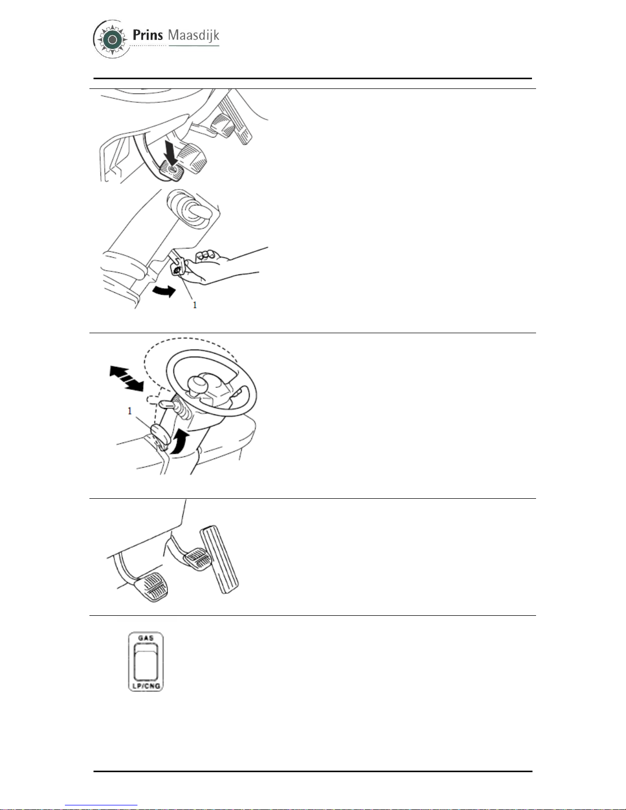
1 – Release lever
Parking brake pedal
Use the parking brake pedal when parking or stopping.
1. When engaging the parking brake, while stepping on the
brake pedal, fully press down on the parking brake pedal.
2. To disengage the parking brake pedal, while stepping on
the brake pedal, pull the release lever toward you.
►Warning!
• Before operating the parking brake pedal, step on the
brake pedal and always confirm that the vehicle has come
to a stop.
• When parking on a slope, apply wheel chocks to the
wheels.
• Traveling without releasing the brake will decrease the
brake performance.
1 – Tilt adjustment lever
Tilt steering adjustment
1. The steering wheel position may be adjusted back and
forth while the tilt steering adjust lever up.
2. Lowering the lever at the proper position fixes the
steering wheel at that position.
3. After the adjustment, try to move the steering wheel back
and forth to see that it is fixed.
►Caution!
The steering wheel position must be adjusted before
starting the vehicle.
Adjustment during traveling must be avoided.
Pedals
From the right: accelerator pedal, brake pedal and inching
pedal.
Accelerator pedal stays neutral even when control lever is
shifted to forward-reverse, due to accelerator switch.
The vehicle will move only when accelerator pedal is
depressed.
Fuel switch (Gasoline/LPG models)
This is a switch to turn on and off the LPG or gasoline fuel feeder
OFF – horizontal position
Engine cannot be started up since no fuel is fed
LPG – low position
GAS – upper position
Note:
• With the ignition switch OFF, no fuel will be fed even if the fuel switch is
positioned at LPG or GAS.
• To turn off the LPG model engine, turn the fuel switch OFF, and run the
engine until it naturally stops. After the engine has stopped, take out the
gas tank, close the valve, turn the ignition switch OFF, and remove the key.
Table of contents


