Jet EQUIPMENT & TOOLS "W" Series User manual

OPERATOR'S MANUAL
“W” Series Premium Pallet Trucks
JET EQUIPMENT & TOOLS, INC. P.O. BOX 1349 253-351-6000
A WMH Company Auburn, WA 98071-1349 Fax 800-274-6840
www.jettools.com e-mail jet@jettools.com M-140075 2/01

2
Important Information
1-YEAR JET offers a one-year limited
LIMITED WARRANTY warranty on this product
REPLACEMENT PARTS
Replacement parts for this tool are available directly form JET Equipment & Tools.
To place an order, call 1-800-274-6848. Please have the following information ready:
1. Visa, MasterCard, or Discover Card number
2. Expiration date
3. Part number listed within this manual
4. Shipping address other than a Post Office box.
REPLACEMENT PART WARRANTY
JET Equipment & Tools makes every effort to assure that parts meet high quality and durability
standards and warrants to the original retail consumer/purchaser of our parts that each such
part(s) to be free from defects in materials and workmanship for a period of thirty (30) days from
the date of purchase.
PROOF OF PURCHASE
Please retain your dated sales receipt as proof of purchase to validate the warranty period.
LIMITED TOOL AND EQUIPMENT WARRANTY
JET makes every effort to assure that its products meet high quality and durability standards and warrants to
the original retail consumer/purchaser of our products that each product be free from defects in materials
and workmanship as follows: 1 YEAR LIMITED WARRANTY ON THIS JET PRODUCT. Warranty does not
apply to defects due directly or indirectly to misuse, abuse, negligence or accidents, repairs or alterations
outside our facilities or to a lack of maintenance. JET LIMITS ALL IMPLIED WARRANTIES TO THE
PERIOD SPECIFIED ABOVE FROM THE DATE THE PRODUCT WAS PURCHASED AT RETAIL.
EXCEPT AS STATED HEREIN, ANY IMPLIED WARRANTIES OR MECHANTABILITY AND FITNESS ARE
EXCLUDED. SOME STATES DO NOT ALLOW LIMITATIONS ON HOW LONG THE IMPLIED
WARRANTY LASTS, SO THE ABOVE LIMITATION MAY NOT APPLY TO YOU. JET SHALL IN NO
EVENT BE LIABLE FOR DEATH, INJURIES TO PERSONS OR PROPERY OR FOR INCIDENTAL,
CONTINGENT, SPECIAL OR CONSEQUENTIAL DAMAGES ARISING FROM THE USE OF OUR
PRODUCTS. SOME STATES DO NOT ALLOW THE EXCLUSION OR LIMITATION OF INCIDENTAL OR
CONSEQUENTIAL DAMAGES, SO THE ABOVE LIMITATION OR EXCLUSION MAY NOT APPLY TO
YOU. To take advantage of this warranty, the product or part must be returned for examination, postage
prepaid, to an authorized service station designated by our Auburn office. Proof of purchase date and an
explanation of the complaint must accompany the merchandise. If our inspection discloses a defect, JET
will either repair or replace the product or refund the purchase price, if we cannot readily and quickly provide
a repair or replacement, if you are willing to accept such refund. JET will return repaired product or
replacement at JET’s expense, but if it is determined there is no defect, or that the defect resulted from
causes not within the scope of JET’s warranty, then the user must bear the cost of storing and returning the
product. This warranty gives you specific legal rights, and you have other rights, which vary, from state to
state.
JET Equipment & Tools •
••
•P.O. Box 1349, Auburn, WA 98071-1349 •
••
•(253) 351-6000

3
WARNING
• Read and understand the entire operator’s manual before using the pallet truck.
• Do not place hands or feet under the pallet truck at any time.
• Do not operate a loaded pallet truck on ramps or inclines.
• Do not tip load pallet truck forks. This may cause damage to the forks and personal
injury if the rear of the pallet truck suddenly "pops up".
• Never leave a loaded pallet truck unattended in the raised position. Always lower
load to the floor.
• Do not load pallet truck beyond its rated capacity.
• Secure load before transporting.
• To prevent accidental tipping, make sure load is centered on the forks.
• Do not move a loaded pallet truck by other than manual force.
• Failure to comply with these warnings may result in personal injury and/or property
damage.
The specifications in this manual are given as general information and are not binding. JET Equipment
& Tools reserves the right to effect, at any time and without prior notice, changes or alterations to parts,
fittings, and accessory equipment deemed necessary for any reason whatsoever.

4
Table of Contents
Warranty .....................................................................................................................................2
Warnings.....................................................................................................................................3
Table of Contents........................................................................................................................4
Assembly ....................................................................................................................................5
Specifications..............................................................................................................................6
Operation....................................................................................................................................7
Lubrication...................................................................................................................................7
O-Ring & Seal Kit Replacement...................................................................................................8
Valve Cartridge & O-Ring Replacement.......................................................................................8
Cleaning Release Valve ..............................................................................................................8
Adjusting Up-Down Cam..............................................................................................................8
Troubleshooting...........................................................................................................................9
Parts Breakdown..................................................................................................................10-12
Parts List..............................................................................................................................13-14
Test Certificate..........................................................................................................................15
Introduction
Congratulations on your purchase of a JET “W” Series Premium Pallet Truck.
To better understand the proper use and safe operation of this pallet truck, please take a few
minutes to carefully read and follow the instructions contained in this manual. When finished
reading and understanding the manual, please file in a safe and convenient location for the life of
the pallet truck.
You will notice several important features about your JET Premium Pallet Truck. It features a 2-
7/8” lowered height, rounded fork tips and nylon entry/exit rollers to provide easy entry and exit of
pallets.
A large, easy-to-use ergonomic handle with a 200°turning radius allows maximum
maneuverability. The articulated steer wheel axle helps maintain floor contact on uneven
surfaces.
The cast iron pump design features top-of-the-stroke and overload by-pass systems, hardened
and chromed ram and piston, and a single point valve service for easy replacement. A special
lowering valve allows you to control the rate of descent and prevent “shock” loads.
Your JET Premium Pallet Truck is designed and built to give you years of trouble-free service
with minimum maintenance and service attention.
Record Your Purchase Information Here
Purchased from _________________________________ Date _____________________
Model Number ________________________ Stock Number __________________________
Serial Number ________________________ Date in Service __________________________

5
Assembly
Note: Individual pallet trucks are assembled and ready to use. Pallet trucks purchased in crate
quantities (6 units to a crate) require some assembly. Match the “letter” label on the handle
assembly to the “letter” label on the frame, prior to assembly.
Tools Required for Assembly:
• Hammer
• 3mm Hex Wrench
• Pliers
To attach handle assembly to the frame:
1. Unscrew the hex socket screw.
6. Tap out pump retainer pin.
2. Tap out pivot pin.
7. Feed the chain through
the hole in the pivot pin.
3. Align the holes in the handle with
the holes in the pump body. Tap
the pivot pin into the handle and
pump body.
4. Using pliers, turn the pivot pin until
spring pin hole’s line up.
5. Using a hammer, tap the spring pin
into the pump body and pivot pin.
Reinstall the hex socket screw.
8. Place the bottom of the head
through the lowering valve.

6
Specifications
Model Stock#W1W2L1L2 H1 H2 A
(dxw) B(dxw) C Net
Wt.
PT-2036W 140070 20.5” 6.25” 36” 16.5” 7-3/4” 2-7/8” 7”x2” 2-7/8”x3-11/16” 47” 170
PT-2042W 140071 20.5” 6.25” 42” 16.5” 7-3/4” 2-7/8” 7”x2” 2-7/8”x3-11/16” 47” 179
PT-2048W 140072 20.5” 6.25” 48” 16.5” 7-3/4” 2-7/8” 7”x2” 2-7/8”x3-11/16” 47” 187
PT-2736W 140073 27” 6.25” 36” 16.5” 7-3/4” 2-7/8” 7”x2” 2-7/8”x3-11/16” 47” 183
PT-2742W 140074 27” 6.25” 42” 16.5” 7-3/4” 2-7/8” 7”x2” 2-7/8”x3-11/16” 47” 192
PT-2748W 140075 27” 6.25” 48” 16.5” 7-3/4” 2-7/8” 7”x2” 2-7/8”x3-11/16” 47” 200

7
Operation
To raise the forks, push lever down and pump
the handle to the desired height.
To lower forks, pull lever up. The lever is spring
loaded and will return to the neutral position.
To freely move the handle, set the lever in the
center neutral position.
To lift a load:
1. Lower forks to lowest position.
2. Insert forks under load or into pallet.
3. Push the lever down.
4. Move handle up and down until forks reach
desired height.
To move a load:
1. Place lever in center neutral position.
2. Pull or push to desired location.
To lower a load:
1. Pull lever up.
2. Pull forks away from load.
Lubrication
Check the oil level annually by removing #65
screw. When changing or adding oil, fill the tank
through #65 screw hole, to 80% capacity with
hydraulic jack oil approximately 2” deep in pump
housing. See pump housing breakdown.
There are five oil points located on the truck.
One is located on the bearing base #97, one on
pressure plate #5, and the others on the load
wheel frame #22. Grease the five points on a
semi-annual basis.
Lightly oil all moving parts.
O-Ring and Seal Replacement for Piston
and Plunger Piston
Note: Refer to Pump Breakdown
1. Raise the pallet truck by pumping handle.
2. Remove the C-clip #69B. This will free the
pump and handle assembly from the pallet
truck

8
3. Remove screw (#83) and empty the oil into
a suitable container. Pump handle until all
oil has drained.
4. Pull out ram piston or plunger piston.
5. Remove pump cap (#66) for Piston
6. Remove all O-Rings & Seals.
7. Insert new O-Ring or Seal one at a time
making sure to replace with the same size
that was removed.
8. Reassemble.
9. Refill oil to correct level through #65. 80%
capacity or approximately 2 inches deep in
reservoir.
O-Ring and Seal Replacement for Valve
Cartridge
1. Remove screw (#83) and empty the oil into
a suitable container. Pump handle until all
oil has drained.
2. Tap out spring pin (#79).
3. Remove the lowering lever (#76).
4. Unscrew the valve cartridge (#80).
5. Remove all O-Rings & Seals.
6. Insert new O-Ring or Seal one at a time
making sure to replace with the same size
that was removed.
7. Assemble the valve cartridge and lowering
lever.
8. Refill oil to correct level #65. 80% capacity
or approximately 2 inches deep in reservoir.
Cleaning the Release Valve
(Bleeding the Pump)
Over time the release valve assembly may
become clogged with debris. To clean the
release valve:
1. Pump handle quickly raising pallet truck to
full extent. While continuing pump action,
pull lever to down position.
2. When forks reach total down position, valve
is flushed. Repeat if necessary.
Adjusting Up-Down Cam
1. Place lever in the neutral position.
2. Loosen #78 hex nut.
3. Adjust #77 hex socket screw while pumping
the handle.
4. The cam is properly adjusted when pumping
the handle in the neutral position causes no
movement.

9
Troubleshooting
Possible problems could arise in the operation of your hydraulic pallet truck. Their probable
causes(s) and corrective action(s) follow:
Condition Probable Causes Corrective Action
Hydraulic unit does not lift Oil low in tank Make sure there is no oil leakage
from valve and add oil
Steel ball not seated in hydraulic
unit Place the lever in the down
position and pump the handle
repeatedly
Worn U-packing in ram cylinder Consult authorized repair station
Once lifted truck lowers by itself Steel ball not seated in hydraulic
unit See “Cleaning Release Valve” on
page 8
Worn U-packing in ram cylinder See “Cleaning Release Valve” on
page 8
Release valve not seated
properly See “Cleaning Release Valve” on
page 8
Release valve not adjusted
properly Reload truck within load capacity
and adjust valve by pressure
adjustment screw
Oil leakage from each valve Tighten plug of each valve
Fork does not lower Cam broken Replace cam chain
Up-down cam nut out of
adjustment Refer to “Adjusting Up-Down
Cam” on page 8
Broken fork rods and linkage Replace broken parts
Lever does not set at Up-down Cam nut out of adjustment Refer to “Adjusting Up-Down
Cam” on page 8

1
0
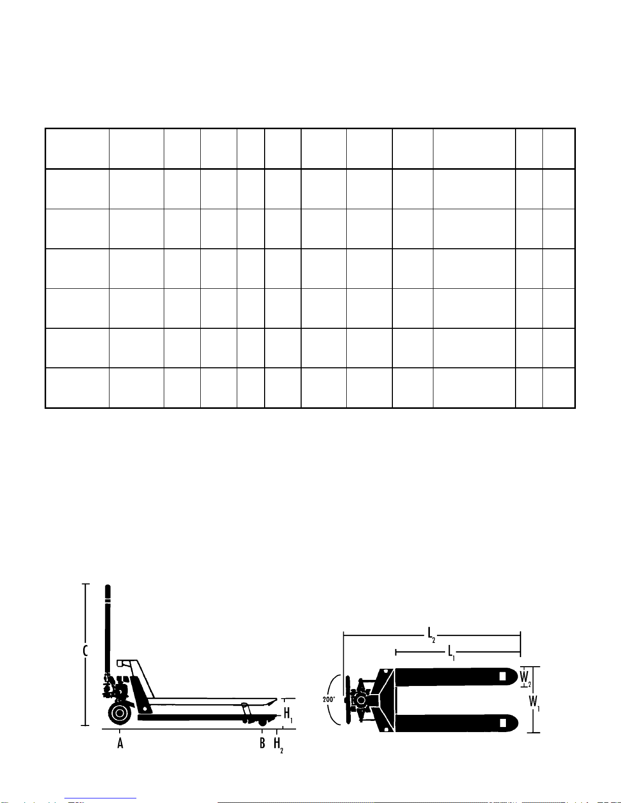
Parts List for the PT-2748W Premium Pallet Truck
Index Part
No. No. Description Size Qty.
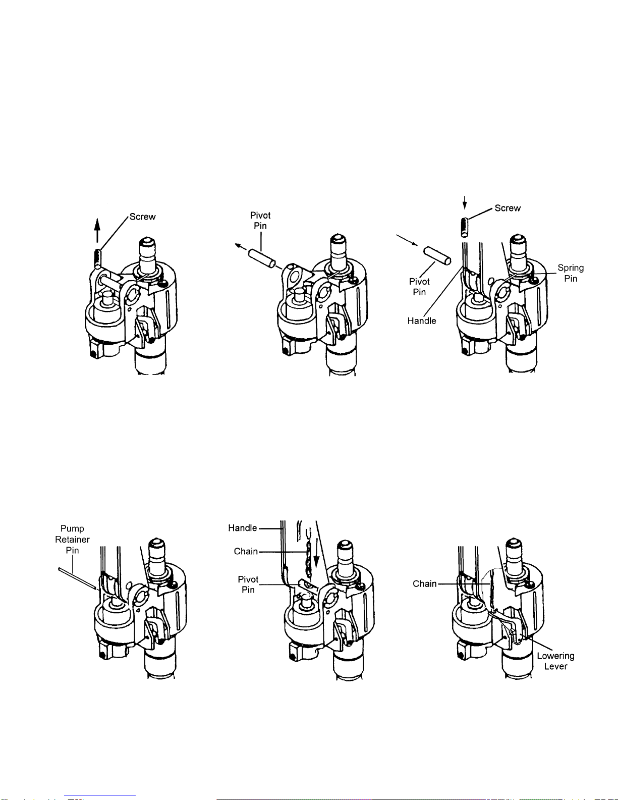
1..........PT2748W-01.....................Handle Assembly Complete.............................................................1
2..........PT2748W-02.....................Spring Pin......................................................8x50mm...................1
3..........PT2748W-03.....................Bearing ...........................................................................................1
4..........PT2748W-04.....................Spring Pin......................................................5x35mm...................2
5..........PT2748W-05.....................Pressure Plate.................................................................................1
6..........PT2748W-06.....................C-clip...............................................................................................1
7..........PT2748W-07.....................Wheel Shaft ....................................................................................1
8..........PT2748W-08.....................C-clip...............................................................................................2
9..........PT2748W-09.....................Washer ...........................................................................................2
10........PT2748W-10.....................Steering Wheel Complete w/Bearings..............................................2
............BB-6240VV.......................Steer Wheel Bearing .......................................................................4
11........PT2748W-11.....................C-clip...............................................................................................2
12........PT2748W-12.....................Steer Wheel Hub Cap......................................................................2
13........PT2748W-13.....................Arm Pin...........................................................................................2
13A .....PT2748W-13A..................Bushing...........................................................................................2
14........PT2748W-14.....................Lifting Link For 27” Wide Frame.......................................................1
............PT2048W-14.....................Lifting Link For 20.5” Wide Frame....................................................1
15........PT2748W-15.....................Bushing...........................................................................................2
16........PT2748W-04.....................Spring Pin......................................................5x35mm...................2
16A .....PT2748W-16A..................Bushing...........................................................................................2
17........PT2748W-17.....................Push Rod For 48” Forks..................................................................2
............PT2742W-17.....................Push Rod For 42” Forks..................................................................2
............PT2736W-17.....................Push Rod For 36” Forks..................................................................2
18........PT2748W-18.....................Spring Pin......................................................5x30mm...................4
19........PT2748W-19.....................Roller..............................................................................................4
20........PT2748W-18.....................Spring Pin......................................................5x30mm...................2
21........PT2748W-21.....................Shaft...............................................................................................2
21A .....PT2748W-21A..................Bushing...........................................................................................4
22........PT2748W-22.....................Load Wheel Frame..........................................................................2
22A .....PT2748A-055B .................Grease Fitting..................................................................................4
23........PT2748W-18.....................Spring Pin......................................................5x30mm...................2
26........PT2748W-26.....................Shaft...............................................................................................2
27........PT2748W-27.....................Shaft...............................................................................................2
28........PT2748W-28.....................Washer ...........................................................................................4
29........PT2748W-29.....................Load Wheel Complete w/Bearings...................................................2
............BB-6204VV.......................Load Wheel Bearing........................................................................4
30........PT2748W-30.....................Load Wheel Dust Cover...................................................................4
31........PT2748W-31.....................Dust Cover Lock Ring......................................................................4
33........PT2748W-33.....................C-clip...............................................................................................1
34........PT2748W-34.....................Long Shaft For 27” Wide Frame.......................................................1
............PT2048W-34.....................Long Shaft For 20.5” Wide Frame....................................................1
35........N/A...................................Fork Frame .....................................................................................1
36........PT2748W-36.....................C-clip...............................................................................................2
37........PT2748W-37.....................Entry Roller.....................................................................................2
38........PT2748W-38.....................Shaft...............................................................................................2
39........PT2748W-39.....................Stop Roller......................................................................................1
40........PT2748W-40.....................Spring Pin......................................................4x22.........................1
41........PT2748W-41.....................Handle ............................................................................................1
42........PT2748W-42.....................Spring Pin......................................................6x30.........................1
43........PT2748W-40.....................Spring Pin......................................................4x22.........................1
44........PT2748W-44.....................Lowering Lever................................................................................1

1
1
Index Part
No. No. Description Size Qty.
45........PT2748W-45.....................Lowering Linkage............................................................................1
46........PT2748W-46.....................Chain..............................................................................................1
47........PT2748W-47.....................Anchor chain...................................................................................1
48........PT2748W-48.....................Pressure Roller ...............................................................................1
49........PT2748W-49.....................Pressure Roller Shaft ......................................................................1
50........PT2748W-50.....................Pivot Pin..........................................................................................1
51........PT2748W-51.....................Spring Pin......................................................4x30.........................2
52........PT2748W-52.....................Spring For Lowering Lever ..............................................................1
53........PT2748W-53.....................Bushing...........................................................................................2
53A .....PT2748W-53A..................Plunger Piston.................................................................................1
54........PT2748W-54.....................Spring Cap......................................................................................1
55........PT2748W-55.....................Plunger Spring ................................................................................1
56........PT2748W-56.....................Plunger Cylinder..............................................................................1
57........PT2748W-94.....................O-ring & Seal Kit*...........................................DH18........................1
58........PT2748W-94.....................O-ring & Seal Kit*...........................................DH18........................1
59........PT2748W-59.....................Spring Pin.......................................................................................1
60........PT2748W-60.....................Pump Body .....................................................................................1
61........PT2748W-61.....................Washer ...........................................................................................1
62........PT2748W-62.....................Screw Plug......................................................................................1
63........PT2748W-94.....................O-ring & Seal Kit*...........................................32x3.5......................1
64........PT2748W-94.....................O-ring & Seal Kit*...........................................UN32........................1
65........PT2748W-65.....................Screw.............................................................M6x8........................3
66........PT2748W-66.....................Pump Cap.......................................................................................1
67........PT2748W-94.....................O-ring & Seal Kit*...........................................P62 ..........................1
68........SB-3/4 ..............................Ball.................................................................3/4............................1
69........PT2748W-69.....................Piston..............................................................................................1
69A .....PT2748W-69A..................Washer ...........................................................................................1
69B .....PT2748W-69B..................C-clip...............................................................................................1
70........PT2748W-94.....................O-ring & Seal Kit*...........................................P31 ..........................1
71........PT2748W-94.....................O-ring & Seal Kit*...........................................UN32........................1
72........PT2048W-72.....................Pin..................................................................................................1
73........PT2748W-94.....................O-ring & Seal Kit*...........................................P15 ..........................1
74........PT2748W-94.....................O-ring & Seal Kit*...........................................P17 ..........................1
75........PT2748W-94.....................O-ring & Seal Kit*...........................................P22 ..........................1
76........PT2748W-76.....................Lowering Lever................................................................................1
77........PT2048W-77.....................Threaded Pin...................................................................................1
78........PT2748W-78.....................Hex Nut...........................................................................................1
79........PT2748W-79.....................Tension Pin Handle.........................................................................1
80........PT2748W-80.....................Valve Cartridge 1.............................................................................1
80A .....PT2748W-80A..................Valve Cartridge 2.............................................................................1
81........PT2748W-94.....................O-ring & Seal Kit*...........................................11x2.4......................1
82........PT2748W-82.....................Washer ...........................................................................................1
83........PT2748W-83.....................Bolt .................................................................................................1
84........PT2748W-84.....................Overload Valve Assembly** (#84-91)...............................................1
85........PT2748W-84.....................Steel Ball**......................................................................................1
86........PT2748W-84.....................Spreader Spring Bracket**...............................................................1
87........PT2748W-84.....................Spreader Spring** ...........................................................................1
88........PT2748W-84.....................Supporting Bracket**.......................................................................1
89........PT2748W-84.....................Spreader Spring Bolt** ....................................................................1
90........PT2748W-84.....................Washer**.........................................................................................1
91........PT2748W-84.....................Fixed Screw**..................................................................................1
............PT2748W-92.....................Pump Handle Wheel Assembly........................................................1
93........PT2748W-93.....................Pump Assembly Complete ..............................................................1
............PT2748W-94.....................O-ring & Seal Kit* (57,58,63,67,70,71,73-75,81)..............................1
............PT2748W-95.....................Label Kit..........................................................................................1
96........PT2748A-055B .................Grease Fitting..................................................................................1

1
2
97........PT2748W-97.....................Bearing Base...................................................................................1
98........PT2748W-98.....................Set Screw.......................................................M8x10......................1
99........PT2748W-99.....................Dust Boot........................................................................................1
*Available only in the O-ring & Seal kit - PT2748W-94
**Available only in the Overload Valve Assembly - PT2748W-84

1
3
Parts Breakdown

1
4
Parts Breakdown

1
5
Pump Breakdown

1
6
JET EQUIPMENT & TOOLS, INC. 2415 West Valley Highway N Fax: 800-274-6840
A WMH Company P.O. Box 1349 Phone: 253-351-6000
www.jettools.com Auburn, WA 98071-1349 e-mail: jet@jettools.com
This manual suits for next models
6
Table of contents
Other Jet Truck manuals