9
Owner and Operator’s Manual
TM
-XL
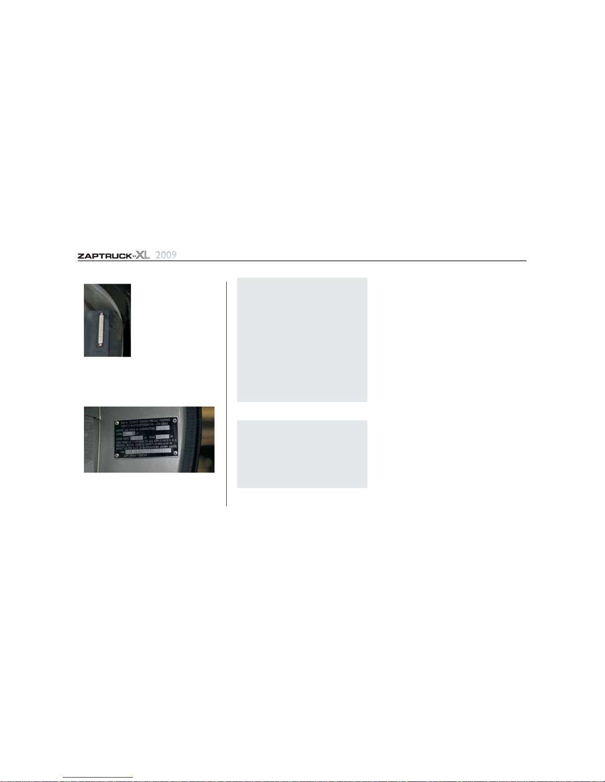
1.(VIN)
Vehicle Identification
Number
2.Vehicle Nameplate
3.Branding
VIN is printed on the lower
frame of driver's seat in the
cab, the upper left of the
instrument panel and on the
nameplate.
The nameplate is marked with Vehicle
Identification Number (VIN).It is riveted on the
left B-pillar inside plate (Fig.2).
Body surface has the ZAP logo in font and back.
ZAPTRUCK-XL and Zero Emissions are also
branded on the sides.
3. Vehicle Marking
General Information Safety and Important Notes
Fig. 2
Fig. 1
Warning!
Avoid any dangerous operation such as
sudden start and acceleration, violent
steering as the vehicle could go out of
control, roll over or become damaged.
Avoid driving on extremely rough roads.
All passengers must wear safety belts when
the vehicle is in operation.
Do not overload the vehicle.
The vehicle electrical circuit is high-tension.
Do not touch any lines or attempt repair
unless you first disconnect the battery.
1.Non-Permissible to Modify
2.Inspection of NewVehicle
Owners should inspect the following items after
Warning!
Vehicle modification is absolutely
prohibited as it may impair the vehicle's
performance, life, safety provisions and may
even be illegal by state law.Vehicle damage
and personal injury and death caused by
vehicle modification is not within the scope
of the limited warranty.
taking delivery of the new vehicle in order to
ensure its safety provisions and reliability:
Check all fixings of the vehicle,especially safety
parts such as steering nut, braking and wheel
nuts,etc.
Check to see if there is any air and water leaks.
Check oil level of gear box and rear axle.
Check fluid level of battery.
Check tire pressure.
accessories are complete.
After starting,check to see if all instruments
are functioning properly.
When performing service,make sure the foot
and parking brakes are working properly.
Check that steering mechanism is functioning
Normally.
Check the driveline for abnormal noise.
In order to maintain the vehicle in good running
condition, please service the vehicle according
to this manual.
Check that whether attached tools and
3. Vehicle Maintenance


 Operator's manual")


