manuals.online logo
Brands
  1. Home
  2. •
  3. Brands
  4. •
  5. Prior Scientific
  6. •
  7. Scanner
  8. •
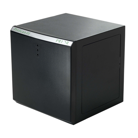
  9. Prior Scientific ProScan III Programming manual

Prior Scientific ProScan III Programming manual

PLEASE READ THE INSTRUCTIONS BEFORE
ATTEMPTING TO USE THE PROSCAN SYSTEM
IDENTIFYING YOUR SYSTEM COMPONENTS
CONNECTING YOUR SYSTEM
• Save this manual as it contains important safety information and operating instructions.
• Before using the stage system, please follow and adhere to all warnings, safety and operating instructions located
on the product and in this user manual.
• Do not expose the product to open flames, extreme hot or cold temperatures, water or moisture.
• Do not allow objects to fall on or liquids to spill on the product.
• Connect the AC power cord only to designated power sources as marked on the product.
• Make sure the electrical cord is located so that it will not be subject to damage.
• To reduce the risk of damage, unplug the product from the power source before connecting the components together.
•DANGER - never alter the AC cord or plug. If the plug will not fit into the outlet, have a proper outlet installed
by a qualified electrician.
• Use only the proper type of power supply cord set (provided with the system) for this unit.
• Do not attempt to disassemble the product. Doing so will void the warranty. This product does not contain
consumer serviceable components. Service should be performed by authorized service centers.
PROSCANTMIII QUICK START INSTRUCTIONS
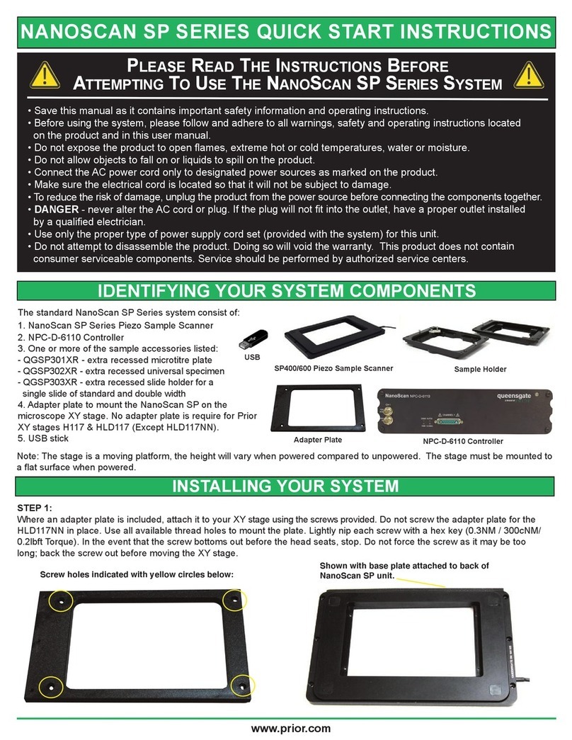
The standard ProScan system
consists of:
(1)- *Controller box
(1)- RS232 cable
(1)- USB cable
(1)- Power cable
(1)- CS200 Joystick(s)
* Additional add-on modules can be added to
increase functionality such
asadding additional filter
wheels or shutters, etc.
Power Cable RS232 Cable
Shutter 1
Filter 1
Encoder
Z
Only on XYZEF
model Encoder
YEncoder
XEncoder
ZEncoder
YEncoder
X
Focus
Stage
RS232 - 1
RS232 - 1
RS232 - 2
RS232 - 2
USB
USB
Joystick -
CS200
CANBUS CANBUS
TTL TTL
Power
Socket
On/Off
Power Switch
Filter 2
Filter 3
Filter 2
Focus/
Filter 1
Filter 3
Shutter 2
Shutter 3
Shutter 1
Shutter 2
Shutter 3
Controller Box shown with
Additional Add-on Module
Power
Indicator Communication
Indicator
Status
Indicator
Product-V2-1122-EN-US
USB Cable
CS200
Joysticks
ProScanTMIII ZFE Model
ProScanTMIII XYZ & XYZEF Models
Joystick -
CS200
Power
Socket
On/Off
Power Switch
Please Note: Always turn off
the controller box prior to
attaching or removing
any accessories.
INSTALLING ACCESSORIES AND STAGES
INSTALLING FOCUS SYSTEMS
All the connectors are labelled, when plugging and unplugging connector always turn the power off.
All stages connect to the 25 way connector labelled “STAGE”. Switch off the power using the power switch.
Connect and firmly and screw in the cable both at the controller and stage. If you have an encoded stage, plug and
screw in the encoder cables, these are labelled X and Y, ensure the X cable is plugged into the connector on the
ProScan III labelled X. Ensure the Y cable is plugged into the connector on the ProScan III labelled Y. Power on the
ProScan III, the ProScan III will now auto detect the stage and setup the features associated with that stage in software.
All focus systems connect to the 15 way connector labelled “FOCUS” or “FILTER 1” for H31ZFE controller. Switch off
the power using the power switch. Connect and firmly and screw in the cable to the controller.
INSTALLING THE PRIOR COMMUNICATION PORT FOR USB 
For information on installing the Prior communication port for USB operation - Window XP please visit the following
web page on the Prior Scientific web site: http://www.prior-us.com/Customer-Support/Download-Centre/
INSTALLING FILTER WHEEL AND SHUTTERS
It is recommended that filters be installed before mounting the filter wheel to a microscope.
1. Select filter position required for loading, by checking the number displayed in the
load position indicator window (A)
2. Remove the magnetic covers (B) from the load port.
3. Remove lock ring (C) by unscrewing from the filter holder cell with the tool (D) provided.
4. Insert desired filter and replace lock ring.
5. Repeat this process for all the desired filter positions.
6. Replace magnetic covers.
All filter wheels connect to the 15 way connector, it can be labelled “FILTER” or
“AXIS A”, you can select “FILTER 1”, “FILTER 2” or “AXIS A”.
Switch off the power using the power switch.
Connect and firmly and screw in the cable both at the controller and filter wheel.
All shutters connect to the round connector labelled “S”, you can select “S1”, “S2”
or “S3”.Switch off the power using the power switch. Connect and firmly and screw in
the cable to the controller. Prior filter wheels and shutters are supplied with the correct adapter flanges fitted, for the
specified microscope stand. Therefore the mounting of this equipment uses exactly the same procedure used when
fitting the microscopes lamphouse. All Prior filter wheels and shutters are manufactured with C mount threads. The
addition of a male to male C mount adapter (Part No. HF207) allows these units to be mounted to a microscope
camera port, if required.
Note: Shutter should always be installed with the silver face towards the lamphouse.
INSTALLING FOURTH AXIS OR AUXILIARY AXIS EQUIPMENT
Fourth axis or auxiliary axis equipment connects to the 15 way connector, labelled “AXIS A”. Switch off the power
using the power switch. Connect and firmly and screw in the cable both at the controller and the equipment. The
controller will automatically detect Prior accessories and set them up for use. For non-standard user equipment use
the FOURTH commands in the ASCII commands section.
INSTALLING CS200 SERIES JOYSTICK
Ensure the system is switched off. Power on the system. The CS200 Joystick will be detected by the ProScan III
controller.
INSTALLING A LUMEN 200PRO ILLUMINATION SYSTEM
The Lumen 200PRO uses two 15 way connectors. The two 15 way connectors should be connected to “FILTER 1”
and “FILTER 2”, if necessary use “AXIS A”. Switch off the power using the power switch. Connect and firmly and
screw in the cables for both at the controller and two Lumen 15 way connectors. Power on the system.
Prior Scientific, Inc. 80 Reservoir Park Drive, Rockland, MA. 02370
Phone: 781-878-8442 Toll Free: 800-877-2234 Fax: 781-878-8736 Web: www.prior.com
Other manuals for ProScan III

4

Other Prior Scientific Scanner manuals

Prior Scientific NanoScan SP Series Programming manual

Prior Scientific

Prior Scientific NanoScan SP Series Programming manual

Prior Scientific ProScan III User manual

Prior Scientific

Prior Scientific ProScan III User manual

Popular Scanner manuals by other brands

Canon LiDE 300 Online manual

Canon

Canon LiDE 300 Online manual

AutoDia SX45 manual

AutoDia

AutoDia SX45 manual

Epson 00000650 - Perfection 3200 PRO Color Scanner Product support bulletin

Epson

Epson 00000650 - Perfection 3200 PRO Color Scanner Product support bulletin

Extech Instruments IRT500 user guide

Extech Instruments

Extech Instruments IRT500 user guide

Canon Colortrac imagePROGRAF MFP Z36 Service Support Guide

Canon

Canon Colortrac imagePROGRAF MFP Z36 Service Support Guide

Grecom PSR-120 owner's manual

Grecom

Grecom PSR-120 owner's manual

QPIX CBS1400 Guide

QPIX

QPIX CBS1400 Guide

Microtek Bio-6000 user guide

Microtek

Microtek Bio-6000 user guide

RayTek LineScanner MP150 operating instructions

RayTek

RayTek LineScanner MP150 operating instructions

Solid SmartScan50 Application note

Solid

Solid SmartScan50 Application note

Ricoh IS450 operating instructions

Ricoh

Ricoh IS450 operating instructions

ISC EZYiD user manual

ISC

ISC EZYiD user manual

Fujitsu FI-6000NS Specifications

Fujitsu

Fujitsu FI-6000NS Specifications

Panasonic KV-S4065CL - Sf Clr Duplex 65PPM USB 2.0 Lgl 300PG... operating manual

Panasonic

Panasonic KV-S4065CL - Sf Clr Duplex 65PPM USB 2.0 Lgl 300PG... operating manual

SICK microScan3 Core I/O AIDA Mounting instructions

SICK

SICK microScan3 Core I/O AIDA Mounting instructions

Kodak I1420 - Document Scanner installation guide

Kodak

Kodak I1420 - Document Scanner installation guide

RIOTEC DC9250K Programming Quick Guide

RIOTEC

RIOTEC DC9250K Programming Quick Guide

ImageLab FS-5T12 user manual

ImageLab

ImageLab FS-5T12 user manual

manuals.online logo
manuals.online logoBrands
  • About & Mission
  • Contact us
  • Privacy Policy
  • Terms and Conditions

Copyright 2025 Manuals.Online. All Rights Reserved.