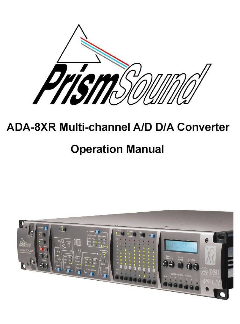
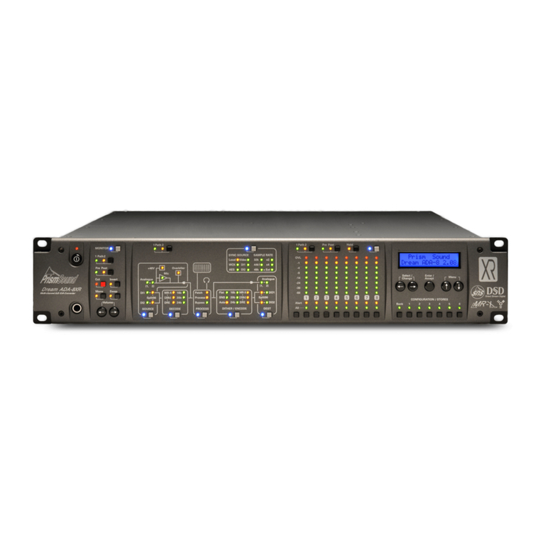
Prism Sound ADA-8XR Service manual

ADA-8XR Multi-channel A/D D/A Converter
Module Reference

Prism Sound ADA-8XR Multi-channel A/D D/A Converter Module Reference - Revision 1.01
© Prism Media Products Limited, 2001-2005 Page 3.1
Module Reference Revision History
Rev Date Author Comments
1.00 4th December 2004 Andy Hudson & Initial release with 2.00 firmware
Ian Dennis
1.01 10th March 2005 Gordon Mills FireWire I/O Module added
Support Contacts
Prism Media Products Limited Prism Media Products Inc
William James House 21 Pine Street
Cowley Road Rockaway
Cambridge CB4 0WX NJ 07866
UK USA
Telephone: +44 1223 424988 Telephone: +1 973 983 9577
Fax: +44 1223 425023 Fax: +1 973 983 9588
Email: tech.support@prismsound.com
Web: http://www.prismsound.com
Or contact your local Prism Sound distributor as detailed on the website.
Trademark Acknowledgements
Digidesign, Pro Tools, Pro Tools 24|MIX, 888|24 I/O, Pro Tools|HD, 192 I/O, 96 I/O, SYNC I/O and DigiLink are
trademarks of Digidesign, a division of Avid Technology Inc.
Direct Stream Digital, DSD, MAC-DSD, SuperMAC and the DSD logo are trademarks of Sony Corporation.
Super Audio CD, SACD and the SACD logo are joint trademarks of Sony Corporation and Philips Electronics N.V.
Microsoft and Windows are trademarks of Microsoft Corporation.
Apple, Macintosh, Core Audio and OS X are trademarks of Apple Computer, Inc.
All trademarks acknowledged
© 2001-2005 Prism Media Products Limited. All rights reserved.
This manual may not be reproduced in whole or part, in any medium, without the written
permission of Prism Media Products Limited.
In accordance with our policy of continual development, features and specifications are
subject to change without notice.

Prism Sound ADA-8XR Multi-channel A/D D/A Converter Module Reference - Revision 1.01
© Prism Media Products Limited, 2001-2005 Page 3.2
Contents
1Introduction............................................................................ 5
2Utility Module PREV039/3/1 ................................................... 6
2.1 Overview ......................................................................................................................6
2.2 Connection ...................................................................................................................6
2.3 Jumper Options............................................................................................................7
3Analogue Line Input Module PREV039/4/2........................... 9
3.1 Overview ......................................................................................................................9
3.2 Fitting the Module.........................................................................................................9
3.3 Connection ...................................................................................................................9
3.4 Module Dependent Input Options Menus ..................................................................10
3.4.1 AI Line Overkillers menu.....................................................................................10
3.4.2 AI Line Level menu .............................................................................................10
3.4.3 AI Line Trim menu...............................................................................................11
3.5 Module Dependent Factory Default Stores................................................................11
3.6 Specifications .............................................................................................................11
4Analogue Line Output Module PREV039/5/1...................... 13
4.1 Overview ....................................................................................................................13
4.2 Fitting the Module.......................................................................................................13
4.3 Connection .................................................................................................................13
4.4 Module Dependent Output Options Menus ...............................................................13
4.4.1 AO Line Level menu ...........................................................................................14
4.4.2 AO Line Trim menu.............................................................................................14
4.5 Module Dependent Factory Default Stores................................................................14
4.6 Specifications .............................................................................................................14
5AES3 I/O Module PREV039/6/1............................................ 16
5.1 Overview ....................................................................................................................16
5.2 Fitting the Module.......................................................................................................16
5.3 Connection .................................................................................................................16
5.4 Module Dependent Input Options Menus ..................................................................17
5.4.1 DI AES Split96 menu ..........................................................................................17
5.5 Module Dependent Output Options Menus ...............................................................17
5.5.1 DO AES Split96 menu ........................................................................................17
5.5.2 DO AES Channel Status menu...........................................................................18
5.6 Module Dependent Preferences Menus ....................................................................18
5.6.1 DI Sync Input menu ............................................................................................18
5.6.2 Cascade Split96 menu........................................................................................18
5.7 Module Dependent Factory Default Stores................................................................18
5.8 Synchronization..........................................................................................................18
5.9 Split96 (two-wire) Operation ......................................................................................19
5.10 Channel Status .......................................................................................................20
5.11 Jumper Options ......................................................................................................20
5.12 Specifications .........................................................................................................21
6Pro Tools I/O Module PREV039/7/1 ..................................... 23
6.1 Overview ....................................................................................................................23
6.2 Getting Started with Pro Tools 24|MIX.......................................................................23
6.3 Fitting the Module.......................................................................................................23
6.4 Hardware Configurations ...........................................................................................23
6.5 Module Dependent Preferences Menus ....................................................................24
6.5.1 Workstation Remote Control menu.....................................................................24
6.6 Module Dependent Factory Default Stores................................................................24
6.7 Synchronization..........................................................................................................25
6.7.1 Master .................................................................................................................26
6.7.2 Slave ...................................................................................................................26
6.7.3 External Master...................................................................................................26
6.8 Remote Control ..........................................................................................................26

Prism Sound ADA-8XR Multi-channel A/D D/A Converter Module Reference - Revision 1.01
© Prism Media Products Limited, 2001-2005 Page 3.3
6.8.1 Sample Rate .......................................................................................................26
6.8.2 Sync Source........................................................................................................27
6.8.3 Input Channel Selection......................................................................................27
6.9 Analogue Line-Up Nomenclature with Pro Tools.......................................................27
6.10 System Interconnection Examples .........................................................................27
6.10.1 Connecting ADA-8XRs to Pro Tools...................................................................28
6.10.2 Combining with 888|24 interfaces, with 888|24 as master .................................29
6.10.3 Combining with 888|24 interfaces, with ADA-8XR as master.............................30
7Pro Tools HD I/O Module PREV039/8/1 ............................... 31
7.1 Overview ....................................................................................................................31
7.2 Hardware Configurations ...........................................................................................31
7.3 Getting Started with Pro Tools|HD.............................................................................32
7.4 Fitting the Module.......................................................................................................32
7.5 Module Dependent Preferences Menus ....................................................................32
7.5.1 Workstation Remote Control menu.....................................................................32
7.5.2 HD Workstation Main/Sub menu ........................................................................33
7.6 Module Dependent Factory Default Stores................................................................33
7.7 Interconnection and Synchronization.........................................................................34
7.7.1 Connecting a Single ADA-8XR as a 192 I/O ......................................................34
7.7.2 Connecting a Pair of ADA-8XRs as a Single 192 I/O .........................................34
7.7.3 Connecting a 16AD ADA-8XR as a 192 I/O .......................................................35
7.7.4 Connecting a 16DA ADA-8XR as a 192 I/O .......................................................36
7.7.5 Connecting an ADA-8XR to the ‘Legacy Port’ of a 96 I/O or a 192 I/O ..............36
7.7.6 Synchronization ..................................................................................................36
7.8 Controlling ADA-8XRs from the Pro Tools|HD User-Interface...................................37
7.8.1 Input and Output Routing....................................................................................37
7.8.2 Sample Rate .......................................................................................................37
7.8.3 Sync Source........................................................................................................37
7.8.4 Analogue / Digital Input Selection.......................................................................37
7.8.5 Soft Clip / Overkiller ............................................................................................37
7.8.6 Identify I/O...........................................................................................................38
7.8.7 Miscellaneous .....................................................................................................38
7.9 Analogue Line-Up Nomenclature with Pro Tools.......................................................38
7.10 Using the ADA-8XR with Digidesign Interfaces at high sample rates....................38
7.10.1 Sync differences between the ADA-8XR and Digidesign interfaces ..................38
7.10.2 Modified Loop Sync cabling scheme ..................................................................39
8DSD I/O Module PREV039/9/1.............................................. 40
8.1 Overview ....................................................................................................................40
8.2 Fitting the Module.......................................................................................................40
8.3 Connection .................................................................................................................40
8.4 Module Dependent Input Options Menus ..................................................................41
8.4.1 DI Input Format Selection Menu .........................................................................41
8.5 Module Dependent Output Options Menus ...............................................................41
8.5.1 DO Output Format Selection Menu ....................................................................41
8.6 Module Dependent Preferences Menus ....................................................................42
8.6.1 DI Sync Input Menu ............................................................................................42
8.6.2 DSD Lineup Menu...............................................................................................42
8.7 Module Dependent Factory Default Stores................................................................43
8.8 Synchronization..........................................................................................................44
8.8.1 Synchronizing to SDIF-3 Inputs ..........................................................................44
8.8.2 Synchronizing to SDIF-2 (DSD-RAW) Inputs .....................................................45
8.8.3 Synchronizing to the MAC-DSD Interface ..........................................................45
8.8.4 DSD I/O Module Synchronization Output ...........................................................45
8.9 Sample Rate and Format Conversion........................................................................46
8.10 Specifications .........................................................................................................46
8.10.1 PCM to DSD Performance..................................................................................46
8.10.2 Analogue to DSD Performance ..........................................................................47
8.10.3 DSD to PCM Performance..................................................................................47
8.10.4 (PCM to) DSD to Analogue Performance...........................................................47

Prism Sound ADA-8XR Multi-channel A/D D/A Converter Module Reference - Revision 1.01
© Prism Media Products Limited, 2001-2005 Page 3.4
8.10.5 PCM to PCM (Synchronous Sample Rate Converter) Performance..................48
8.10.6 DB25 Connector .................................................................................................48
9FireWire I/O Module PREV039/10/1 ..................................... 49
9.1 Overview ....................................................................................................................49
9.2 Software Installation...................................................................................................49
9.2.1 Windows PC Workstation ...................................................................................49
9.2.2 Apple Macintosh Workstation .............................................................................50
9.3 Fitting the Module.......................................................................................................50
9.4 Connection .................................................................................................................50
9.5 Module Dependent Preferences Menus ....................................................................51
9.5.1 Workstation Remote Control Menu.....................................................................51
9.5.2 FireWire I/O Configuration Menu ........................................................................51
9.5.3 FireWire GUID Menu ..........................................................................................51
9.6 Module Dependent Factory Stores ............................................................................52
9.6.1 Analogue to Digital / Digital to Analogue (+ Digital)............................................52
9.6.2 16 Channel Analogue to Digital ..........................................................................52
9.6.3 16 Channel Digital to Analogue ..........................................................................52
9.6.4 Analogue to Digital / Digital to Analogue Cascade .............................................53
9.7 Macintosh Workstation Control Panel........................................................................54
9.7.1 Sampling Rate ....................................................................................................54
9.7.2 Synchronization Modes ......................................................................................55
9.7.2.1 Synchronize to FireWire Bus .......................................................................55
9.7.2.2 Synchronize to Workstation.........................................................................55
9.7.2.3 Synchronize to ADA-8 .................................................................................55
9.7.3 Driver Latency.....................................................................................................56
9.7.4 Volume Control ...................................................................................................56
9.8 Windows PC Workstation Control Panel....................................................................56
9.8.1 Device and Channel Names ...............................................................................56
9.8.2 Sampling Rate ....................................................................................................57
9.8.3 Synchronization Modes ......................................................................................58
9.8.3.1 Synchronize to FireWire Bus .......................................................................58
9.8.3.2 Synchronize to Workstation.........................................................................59
9.8.3.3 Synchronize to ADA-8 .................................................................................59
9.8.4 Driver Latency.....................................................................................................60
9.9 Module Firmware Upgrade ........................................................................................61
9.10 Specifications .........................................................................................................62

Prism Sound ADA-8XR Multi-channel A/D D/A Converter Module Reference - Revision 1.01
© Prism Media Products Limited, 2001-2005 Page 3.5
1 Introduction
This section of the manual gives details of the various module options for the ADA-8XR,
including fitment and connection details, performance specifications and any module-specific
menus and operations.
General operation is covered in the Operation Manual, with full firmware-version-specific
menu and operation details being provided in the Firmware Reference.

Prism Sound ADA-8XR Multi-channel A/D D/A Converter Module Reference - Revision 1.01
© Prism Media Products Limited, 2001-2005 Page 3.6
2 Utility Module PREV039/3/1
2.1 Overview
The Utility Module is fulfils a number of miscellaneous I/O functions:
• Stereo analogue Monitor output;
• Stereo digital Monitor output;
• AES11 Reference Sync Input and Output;
• Wordclock or video Reference Sync input;
• Wordclock or Superclock (256xfs) Reference Sync output;
• Serial COM port, RS-232, RS-485 or MIDI format;
The Utility Module is different from the analogue and digital I/O modules described elsewhere
in this manual, which can be interchangeably fitted to the I/O slots. The Utility Module is fitted
inside the ADA-8XR chassis, and is connected with flying leads to the Utility Panel on the
right-hand side of the rear panel (when viewed from the back).
It is unlikely that the user will ever need to replace or reconfigure the Utility Module,
and the information in section 2.3 is provided for information only.
WARNING: Replacing or reconfiguring the Utility Module requires removal of
the top cover of the ADA-8XR. This operation presents a risk of electric
shock, therefore refer this operation to qualified personnel.
2.2 Connection
AES11 (DARS) Reference Sync input and output are provided on female and male XLR
connectors respectively. The AES11 output impedance is 110Ω; the input impedance is
normally 110Ω, but the input termination can be removed via an internal jumper (as described
below) to allow multiple inputs to be daisy-chained if required. Note that operation of the
AES11 Reference Sync input is currently restricted to frame rates between 32kHz and 96kHz.
Wordclock Reference Sync input and output are provided on BNC
connectors. The input impedance is normally 75Ω, but the input
termination can be removed via an internal jumper (as described
below) to allow multiple inputs to be daisy-chained if required.
The input is also able to accept a 75ΩAES3-id reference, or an
analogue video reference (PAL, NTSC or NTSC30). The output
can be set to produce a Superclock (256xfs clock) instead of a
Wordclock, if required, principally for use in Pro Tools
applications. These selections are made through the Menu
System, as described in the Firmware Reference.
The stereo output of the Monitor is available in both analogue and digital formats. The
analogue outputs are on phono (RCA) connectors, but are balanced (see the jumper options
below). The digital output is in AES3-id format on a BNC connector.
The Serial COM port is on a 9-pin male ‘D’ connector, and is configured by default as RS-232
with PC-compatible pinout allowing it to be connected to a PC using a null-modem cable.
Other formats such as RS-485 and MIDI may be configured by jumpering as described below;
see the Firmware Reference for details of support for these other formats.

Prism Sound ADA-8XR Multi-channel A/D D/A Converter Module Reference - Revision 1.01
© Prism Media Products Limited, 2001-2005 Page 3.7
2.3 Jumper Options
Various configurations of the Utility Module are possible by altering jumper positions, or
selecting alternative headers for the connection of the Utility Panel connectors. The figure
and table below describe these options:
Jumper/Header Function
CN1 Coaxial Ref Sync output (WCK, SCK, DARS)
CN2 XLR Ref Sync output (DARS)
CN4 Digital Monitor #1, balanced output for XLR (note 1)
CN5 Analogue Monitor, left channel, unbalanced output (note 1, 2)
CN6 Analogue Monitor, left channel, balanced output
CN7 Digital Monitor #1, unbalanced output for coaxial
CN8 Digital Monitor #2, balanced output for XLR (note 1)
CN9 Digital Monitor #2, unbalanced output for coaxial (note 1)
CN10 Right-channel, analogue monitor unbalanced output (note 1, 2)
CN11 Right-channel, analogue monitor balanced output
CN12 XLR Ref Sync input (DARS)
CN13 Coaxial Ref Sync input (WCK, DARS or video)
CN14 RS-232 COM port (plug 9wD ribbon here for RS-232, default)
CN15 RS-422/485 COM port (plug 9wD ribbon here for RS-422/485)
CN16 Alternative MIDI connector for panel with DIN connectors
CN17 MIDI COM port (plug 9wD ribbon here for MIDI)
LK1 Coaxial Ref Sync out format; 3-5, 4-6: WCK (default); 1-3, 2-4: S/PDIF
LK2 Digital Monitor #1 output format; 1-2: AES3; 2-3: S/PDIF (default)
LK3 Digital Monitor #2 output format; 1-2: AES3; 2-3: S/PDIF (note 1)
LK4 XLR sync input termination: fitted : 110R (default); not fitted: none
LK5 Coaxial sync input termination: fitted : 75R (default); not fitted: none
LK6 RS-232 COM-mode: fitted – RS-232 mode (default), not fitted - other
LK7 Terminate RS-422/485 Rx: fitted – 110R term, not fitted - none
LK8 RS-485 mode: fitted – RS-485 (half -dplx), not fitted RS-422 (full-dplx)
LK9 RS-485 mode: fitted – RS-485 (half -dplx), not fitted RS-422 (full-dplx)
LK10 RS-422/485 COM-mode: fitted – RS-422/485 mode, not fitted - other
LK11 MIDI COM-mode: fitted - MIDI mode, not fitted - other
Note 1: Unused in default configuration
Note 2: It is recommended that the ‘balanced’ configuration be used for analogue Monitor outputs at all times, even if
the cold leg is grounded. The bootstrapping output circuit gives best results in this mode. The unbalanced connector
gives 6dB gain reduction and may produce increased distortion.

Prism Sound ADA-8XR Multi-channel A/D D/A Converter Module Reference - Revision 1.01
© Prism Media Products Limited, 2001-2005 Page 3.8
Jumpers and headers not listed in the above table are either for factory use only, or reserved
for unspecified future use. These should remain in the state in which they left the factory.
The 9-way ‘D’ connector pin-outs for the various serial COM formats are as follows:
Pin-out of 9w male ‘D’ for various serial COM formats:
Pin RS-232 RS-422/485
MIDI
1 IN+
2 RXD RXD- THRU+
3 TXD TXD+ GND
4 OUT-
5 GND GND
6 GND IN-
7 RXD+ THRU-
8 TXD- OUT+
9 GND

Prism Sound ADA-8XR Multi-channel A/D D/A Converter Module Reference - Revision 1.01
© Prism Media Products Limited, 2001-2005 Page 3.9
3 Analogue Line Input Module PREV039/4/2
3.1 Overview
The Analogue Line Input Module type PREV039/4/2 provides eight electronically-balanced
analogue input channels to the ADA-8XR, on eight female XLR connectors.
Input line-up level (sensitivity) is variable for each channel over the range 0dBFS=+5.0dBu to
0dBFS=+24.0dBu, in 0.5dBu steps plus a fine trim.
Each channel has a Prism Sound Overkiller progressive limiter capability, which prevents the
A/D converter from reaching full-scale, even when the input level significantly exceeds the
selected input range. More information about the Prism Sound Overkiller can be found in the
Technical Background section of the Operation Manual.
Control of the input line-up level and trim, and of the Overkillers, is via menus which are
present in the ADA-8XR Menu System if the Module is present.
3.2 Fitting the Module
In most cases, the Module has been factory-fitted so, unless you are fitting the module
yourself, the remainder of this section may be ignored.
The Analogue Line Input Module can be fitted to either Analogue I/O Slot (AIO1 or AIO2) in
the rear of the ADA-8XR (as shown in the Layout section of the Operation Manual). Although
the ADA-8XR can automatically accommodate the module in either position, it is conventional
that analogue input modules are fitted in the upper slot (AIO1) and line output modules in the
lower slot (AIO2). This will provide compatibility with operating examples quoted in these
manuals. An exception is the case of ADA-8XRs configured for 16-channel A/D or D/A
operation, where BOTH AIO slots would contain either line input or line output modules
respectively.
For details of how to fit the Module, refer to the Adjustments and Upgrades section of the
Operation Manual.
3.3 Connection
Connection from a balanced source is straightforward with conventional XLR pinouts: hot (+)
on pin 2, cold (-) on pin 3, with pin 1 connected to the cable screen.
Unbalanced sources should still be connected to the ADA-8XR between pins 2 (+) and 3 (-) of
its input XLR, since the input circuit is balanced. Pin 1 may be commoned to pin 3 depending
on the topology of the driving circuit.
It is important not to connect an unbalanced source between pins 2 and 1 of the
ADA-8XR’s input XLR with pin 3 unconnected, since incorrect levels and/or excessive
interference may result.

Prism Sound ADA-8XR Multi-channel A/D D/A Converter Module Reference - Revision 1.01
© Prism Media Products Limited, 2001-2005 Page 3.10
3.4 Module Dependent Input Options Menus
When an Analogue Line Input Module is selected as an input to a Path, three menus become
available for the appropriate Module Slot in the Module Dependent Input Options section of
the Menu System for that Path. These menus can be reached either using Menu System
navigation keys, or more easily by pressing the blue ‘Access’ button in the ‘Source’ box of the
Mimic panel when it is selected to the desired Path.
The upper left-hand corner of these menus identifies the Module Slot (e.g. ‘AI1’), followed by
an abbreviated indicator of the module type, in this case ‘Lin’ to indicate Line Input.
For more information about the location of these menus within the overall Menu System,
descriptions of the different menu types, key definitions etc. see the Firmware Reference.
3.4.1 AI Line Overkillers menu
The AI Line Overkillers menu is a Special menu. The 'Select/Change' keys and 'Enter/Accept'
have no function. Overkillers for each of the eight channels are enabled and disabled by the
Channel Select buttons. The enabled/disabled state of the Overkillers is reflected in the
Channel Select LEDs whenever this menu is displayed: LEDs for channels with Overkillers
enabled flash, whereas LEDs for channels with Overkillers disabled remain are unlit. The 'All'
button may be used to quickly enable the Overkillers on all eight channels simultaneously,
although they must be disabled individually.
The Overkillers’ thresholds are set automatically in software, according to the input line-up
level selected for each channel. For line-up levels below +8dBu (i.e. in the 0dBFS=+5.0dBu
to 0dBFS=+8.0dBu range) the effectiveness of the Overkillers’ transient limiting is less than
for higher line-up levels.
It is possible to set the assignable ‘Alert’ LEDs to indicate when the Overkiller of each channel
is actually limiting. This is described in the Alerts section of the Firmware Reference.
More information about the Prism Sound Overkiller can be found in the Technical Background
section of the Operation Manual.
3.4.2 AI Line Level menu
The AI Line Level menu is a Per-Channel Selection menu. The input line-up adjustment is
specified in terms of the analogue input amplitude which produces the peak handling level of
the A/D converter (i.e. 0dBFS). The user may adjust the line-up level for each of the eight
channels, over the range 0dBFS=+5.0dBu to 0dBFS=+24.0dBu, in 0.5dBu steps.
A real-time display of the peak-metered level of the current channel is provided on the bottom
line of the screen to facilitate adjustment (this feature is primarily for use with the AI Line Trim
menu, and is described below).
NOTE for Pro Tools users: the ADA-8XR nomenclature for analogue line-up varies from that
used by Pro Tools. Refer to section 6 for more details.
AI1 Lin:
[Overkillers]
AI1 Lin:+18.0dBu
-
1.02 [0dBFS]

Prism Sound ADA-8XR Multi-channel A/D D/A Converter Module Reference - Revision 1.01
© Prism Media Products Limited, 2001-2005 Page 3.11
3.4.3 AI Line Trim menu
The AI Line Trim menu is a Per-Channel Selection menu. The user may finely trim the line-up
level for each of the eight channels by ±0.5dBu in 0.05dBu steps. This control is
supplementary to the AI Line Level menu.
A real-time display of the peak metered level of the current channel is provided on the bottom
line of the screen to facilitate adjustment. The level display shows peak amplitude in dBFS,
i.e. dBs below digital full-scale. Although it should not be necessary to trim the ADA-8XR to
produce accurate line-up levels (the ranges are set very accurately at the factory), line-up with
other equipment can be achieved by connecting the external reference level to the ADA-8XR
and adjusting the trims as follows. If, for example, a +4dBu (0VU) tone is connected, and the
ADA-8XR line-up is being adjusted for 0dBFS=+18dBu, each trim should be set so that the
peak level display reads as close as possible to -14dBFS. Note that the peak level display
does not function when ‘All’ is selected (it cannot show the level of all eight channels at the
same time!).
3.5 Module Dependent Factory Default Stores
Several of the Factory Default Stores (which include A/D Paths) depend on the fitment of an
analogue input module of some kind for correct operation (as described in the Firmware
Reference). If no analogue input module is available, loading these Stores results in any
available input module being assigned to the ‘analogue input’ Path, or no input module being
assigned if there is none available.
3.6 Specifications
Unless otherwise stated, all performance specifications are rms, unweighted, band-limited
20Hz-20kHz, sampling at 96kHz, wordlength 24-bits, analogue I/O line-up at 0dBFS=+18dBu.
Electronically-balanced inputs on female XLR connectors (pin 2 hot)
Differential input impedance: 21k5Ω
Full-scale input range (software controlled):
Range: +5dBu..+24dBu in 0.5dB steps
Trim: ±0.5dB in 0.05dB steps
Absolute gain accuracy: ±0.05dB
Common-mode rejection ratio (CMRR):
60Hz: <-100dB
1kHz: <-90dB
20Hz..20kHz: <-65dB
Overkiller (progressive analogue input limiter):
On/off selection per channel
Automatic software-controlled threshold adjustment
THD+n (997Hz, -1dBFS): -110dB (0.0003%) typical
Dynamic range (997Hz, -60dBFS): 115dB typical
IMD (SMPTE/DIN, 60Hz at -3dBFS and 7kHz at -12dBFS): <-100dB
Maximum aharmonic spurium: (997Hz, -1dBFS): <-130dBFS
AI1 Lin:+0.00dB
-1.02 [Trim]

Prism Sound ADA-8XR Multi-channel A/D D/A Converter Module Reference - Revision 1.01
© Prism Media Products Limited, 2001-2005 Page 3.12
Frequency response:
fs=192kHz, -0.05dB: 6.2Hz..50.2kHz
fs=192kHz, -3dB: <1Hz..77.7kHz
fs=96kHz, -0.05dB: 6.1Hz..43.3kHz
fs=96kHz, -3dB: <1Hz..46.6kHz
fs=48kHz, -0.05dB: 5.5Hz..22.8kHz
fs=48kHz, -3dB: <1Hz..23.3kHz
fs=44.1kHz, -0.05dB: 5.0Hz..20.1kHz
fs=44.1kHz, -3dB: <1Hz..21.4kHz
Passband ripple:
<0.015dB
Interchannel phase difference: <0.03 degrees
Channel separation:
1kHz: >125dB
20Hz..20kHz: >117dB
Group delay: (analogue input to AES3 output): 20/fs
FFT plots made using Prism Sound dScope Series III at 997Hz, 256k points,
Prism-7 window, 16 averages, at fs=96kHz, +18dBu=0dBFS line-up level.

Prism Sound ADA-8XR Multi-channel A/D D/A Converter Module Reference - Revision 1.01
© Prism Media Products Limited, 2001-2005 Page 3.13
4 Analogue Line Output Module PREV039/5/1
4.1 Overview
The Analogue Line Output Module type PREV039/5/1 provides eight electronically-balanced
analogue output channels from the ADA-8XR, on eight male XLR connectors.
Output line-up level (gain) is variable for each channel over the range 0dBFS=+5.0dBu to
0dBFS=+24.0dBu, in 0.5dBu steps plus a fine trim.
Control of the output line-up level and trim is via menus which are present in the ADA-8XR
Menu System if the Module is present.
4.2 Fitting the Module
In most cases, the Module has been factory-fitted so, unless you are fitting the module
yourself, the remainder of this section may be ignored.
The Analogue Line Output Module can be fitted to either Analogue I/O Slot (AIO1 or AIO2) in
the rear of the ADA-8XR (as shown in the Layout section of the Operation Manual). Although
the ADA-8XR can automatically accommodate the module in either position, it is conventional
that analogue output modules are fitted in the lower slot (AIO2) and line input modules in the
upper slot (AIO1). This will provide compatibility with operating examples quoted in these
manuals. An exception is the case of ADA-8XRs configured for 16-channel A/D or D/A
operation, where BOTH AIO slots would contain either line input or line output modules
respectively.
For details of how to fit the Module, refer to the Adjustments and Upgrades section of the
Operation Manual.
4.3 Connection
Connection to a balanced load is straightforward with conventional XLR pinouts: hot (+) on pin
2, cold (-) on pin 3, with pin 1 connected to the cable screen.
An unbalanced load should be connected between pins 2 (+) and 3 (-) of the output XLR. Pin
1 may be connected to pin 3 to ground reference the cold leg if required, and will often give
better results, depending on the topology of the load circuit. Note that in this mode, line-up
levels above 0dBFS=+20dBFS should not be used since the bootstrapping action of the
output circuit may cause clipping.
It is possible to connect unbalanced loads across pins 2 (+) and 1 (gnd) of the output XLR,
albeit with a gain loss of 6dB. This method is not recommended since it may cause increased
distortion.
4.4 Module Dependent Output Options Menus
When an Analogue Line Output Module is assigned as an output Port from a Path, two menus
become available for the appropriate Module Slot in the Module Dependent Output Options
section of the Menu System for that Path. These menus can be reached either using Menu
System navigation keys, or more easily by pressing the blue ‘Access’ button in the ‘Dest’ box
of the Mimic panel when it is selected to the desired Path.

Prism Sound ADA-8XR Multi-channel A/D D/A Converter Module Reference - Revision 1.01
© Prism Media Products Limited, 2001-2005 Page 3.14
The upper left-hand corner of these menus identifies the Module Slot (e.g. ‘AO1’), followed by
an abbreviated indicator of the module type, in this case ‘Lin’ to indicate Line Output.
For more information about the location of these menus within the overall Menu System,
descriptions of the different menu types, key definitions etc. see the Firmware Reference.
4.4.1 AO Line Level menu
The AO Line Level menu is a Per-Channel Selection menu. The output line-up adjustment is
specified in terms of the analogue output amplitude which corresponds to the peak handling
level of the D/A converter (i.e. 0dBFS). The user may adjust the line-up level for each of the
eight channels, over the range 0dBFS=+5.0dBu to 0dBFS=+24.0dBu, in 0.5dBu steps.
NOTE for Pro Tools users: the ADA-8XR nomenclature for analogue line-up varies from that
used by Pro Tools. Refer to section 6 for more details.
4.4.2 AO Line Trim menu
The AO Line Trim menu is a Per-Channel Selection menu. The user may finely trim the line-
up level for each of the eight channels by ±0.5dBu in 0.05dBu steps. This control is
supplementary to the AO Line Level menu.
4.5 Module Dependent Factory Default Stores
Several of the Factory Default Stores (which include D/A Paths) depend on the fitment of an
analogue output module of some kind for correct operation (as described in the Firmware
Reference). If no analogue output module is available, loading these Stores results in any
available output module being assigned to the ‘analogue output’ Path, or no output module
being assigned if there is none available.
4.6 Specifications
Unless otherwise stated, all performance specifications are rms, unweighted, band-limited
20Hz-20kHz, sampling at 96kHz, wordlength 24-bits, analogue I/O line-up at 0dBFS=+18dBu.
Electronically-balanced outputs on male XLR connectors (pin 2 hot)
Differential input impedance: 50Ω
Full-scale output range (software controlled):
Range: +5dBu..+24dBu in 0.5dB steps
Trim: ±0.5dB in 0.05dB steps
Absolute gain accuracy: ±0.05dB
Output balance: >54dB
THD+n (997Hz, -1dBFS): -102dB (0.0007%) typical
Dynamic range (997Hz, -60dBFS): 108dB typical
IMD (SMPTE/DIN, 60Hz at -3dBFS and 7kHz at -12dBFS): <-94dB
Maximum aharmonic spurium: (997Hz, -1dBFS): <-130dBFS
AO1 Lin:+18.0dBu
[Set dBu=0dBFS]
AO1 Lin:+0.00dB
[Set dBu=0dBFS]

Prism Sound ADA-8XR Multi-channel A/D D/A Converter Module Reference - Revision 1.01
© Prism Media Products Limited, 2001-2005 Page 3.15
Frequency response:
fs=192kHz, -0.05dB: 5.2Hz..37.2kHz
fs=192kHz, -3dB: 1.4Hz..74.4kHz
fs=96kHz, -0.05dB: 5.1Hz..38.9kHz
fs=96kHz, -3dB: 1.4Hz..47.4kHz
fs=48kHz, -0.05dB: 5.1Hz..22.6kHz
fs=48kHz, -3dB: 1.4Hz..23.9kHz
fs=44.1kHz, -0.05dB: 5.0Hz..20.8kHz
fs=44.1kHz, -3dB: 1.4Hz..22.0kHz
Passband ripple: <0.005dB
Interchannel phase difference: <0.02 degrees
Channel separation:
1kHz: >115dB
20Hz..20kHz: >110dB
Group delay: (AES3 input to analogue output): 49.5/fs
FFT plots made using Prism Sound dScope Series III at 997Hz, 256k points,
Prism-7 window, 16 averages, at fs=96kHz, +18dBu=0dBFS line-up level.

Prism Sound ADA-8XR Multi-channel A/D D/A Converter Module Reference - Revision 1.01
© Prism Media Products Limited, 2001-2005 Page 3.16
5 AES3 I/O Module PREV039/6/1
5.1 Overview
The AES3 I/O Module type PREV039/6/1 provides eight channels of digital audio input and
output for the ADA-8XR on four AES3 carriers in each direction. The input and output
sections of the module are completely independent - that is, they can be assigned to different
Paths with different sample rates, Sync Sources and other options. The AES3 I/O module can
be thought of as two modules in one - one input module and one output module.
The module can accommodate extended sample rates (up to 192kHz) in Split96 (two-wire) or
high-speed (one-wire) modes, and can output consumer or professional Channel Status.
Inputs and outputs may be jumpered to comply with either AES3 or S/PDIF carrier voltage
levels and impedances.
5.2 Fitting the Module
In most cases, the Module has been factory-fitted so, unless you are fitting the module
yourself, the remainder of this section may be ignored.
The AES3 I/O Module can be fitted to either Digital I/O Slot (DIO1 or DIO2) in the rear of the
ADA-8XR (as shown in the Layout section of the Operation Manual). Although the ADA-8XR
can automatically accommodate the module in either position, it is conventional that general-
purpose (i.e. non-workstation) digital I/O modules are fitted in the upper slot (DIO1) if NO
workstation card is fitted, and in the lower slot (DIO2) if a workstation I/O card is fitted. This
will provide compatibility with operating examples quoted in these manuals. Where an
ADA-8XR is to be fitted for eight-channel Split96 operation, or for 16-channel analogue-to –
AES3 or 16-channel AES3 to analogue operation, AES3 I/O Modules must be fitted to BOTH
DIO slots.
For details of how to fit the Module, refer to the Adjustments and Upgrades section of the
Operation Manual.
5.3 Connection
Connection to the AES I/O Module is by a female 25-way ‘D’ type connector on the rear
panel. This carries all the connections needed for four input and four output AES3 carriers.
The AES3 module is supplied with a ‘squid’ which breaks out the 25-way to ‘D’ to four female
XLR connectors for the AES3 inputs and four male XLR connectors for the AES3 outputs.
To assist in custom cabling applications, the pinout of the squid is shown in section 5.12.
For coaxial connection with S/PDIF or AES3-id equipment, adapters can be used on the
XLRs which connect pin 2 to the coaxial inner and pins 1 and 3 to the coaxial screen.
Alternatively, wire to the 25-way ‘D’ using ‘A’ to inner and ‘B’ + ‘Screen’ to outer. In either
case, set the jumpers for S/PDIF operation as described in section 5.11.

Prism Sound ADA-8XR Multi-channel A/D D/A Converter Module Reference - Revision 1.01
© Prism Media Products Limited, 2001-2005 Page 3.17
5.4 Module Dependent Input Options Menus
When an AES3 I/O Module is selected as an input to a Path, a DI AES Split96 menu for the
relevant module slot becomes available in the Module Dependent Input Options section of the
Menu System for that Path.
The upper left-hand corner of this menu identifies the Module Slot (e.g. ‘DI1’), followed by an
abbreviated indicator of the module type, in this case ‘AES’.
For more information about the location of these menus within the overall Menu System,
descriptions of the different menu types, key definitions etc. see the Firmware Reference.
5.4.1 DI AES Split96 menu
The DI AES Split96 menu is a Single Selection menu - the AES3 I/O Module in question may
be set to ‘Normal’ (two channels per carrier) or ‘Split96’ (one channel per half-speed carrier).
This option only applies to the selected module, when extended sample rates are in use, in
the input direction. If two AES3 I/O Modules are selected as inputs to a Path, two DI AES
Split96 menus are made available, one for each module. If Cascade Split96 mode is enabled
(see section 5.6), setting a single module to Split96 input mode causes both AES3 I/O
Modules to ‘cascade’ to provide eight input channels as described in section 5.9.
5.5 Module Dependent Output Options Menus
When an AES3 I/O Module is selected as an output from a Path, a DO AES Split96 menu and
a DO AES Channel Status menu for the relevant module slot become available in the Module
Dependent Output Options section of the Menu System for that Path.
The upper left-hand corner of this menu identifies the Module Slot (e.g. ‘DO1’), followed by an
abbreviated indicator of the module type, in this case ‘AES’.
For more information about the location of these menus within the overall Menu System,
descriptions of the different menu types, key definitions etc. see the Firmware Reference.
5.5.1 DO AES Split96 menu
The DO AES Split96 menu is a Single Selection menu - the AES3 I/O Module in question may
be set to ‘Normal’ (two channels per carrier) or ‘Split96’ (one channel per half-speed carrier).
This option only applies to the selected module, when extended sample rates are in use, in
the output direction. If two AES3 I/O Modules are selected as outputs from a Path, two DO
AES Split96 menus are made available, one for each module. If Cascade Split96 mode is
enabled (see section 5.6), setting a single module to Split96 output mode causes both AES3
I/O Modules to ‘cascade’ to provide eight output channels as described in section 5.9.
DO1 AES: Normal
Normal Split96
DI1 AES: Normal
Normal Split96

Prism Sound ADA-8XR Multi-channel A/D D/A Converter Module Reference - Revision 1.01
© Prism Media Products Limited, 2001-2005 Page 3.18
5.5.2 DO AES Channel Status menu
The DO AES Channel Status menu is a Single Selection menu. The user may choose the
format of the Chanel Status information embedded in the AES3 or S/PDIF carrier. Two
options are available, ‘Pro’ (professional) and ‘Consumer’. The precise implementation of
each mode is described in section 5.12.
5.6 Module Dependent Preferences Menus
5.6.1 DI Sync Input menu
Each AES3 I/O Module fitted to the ADA-8XR enables a DI Sync Input menu in the Module
Dependent Preferences section of the Menu System. These Single Selection menus control
which AES3 input carrier will be the Sync Source when a Path sourced from that module is
set to sync from that ‘DI’ slot. Options are ‘C1’, ‘C2’, ‘C3’, ‘C4’ and ‘Auto’. ‘C1-4’ select one of
the four input carriers - fixing the Sync Source to that AES3 carrier. ‘Auto’ allows the
ADA-8XR to choose any locked carrier input as described in the section 5.8.
5.6.2 Cascade Split96 menu
If two AES3 I/O Modules are fitted to the ADA-8XR, the Cascade Split96 menu is made
available in the Module Dependent Preferences section of the Menu System. This is a Single
Selection menu that enables or disables Cascade Split96 mode as described in section 5.9.
The default selection is ‘No’, i.e. Cascade Split96 mode is disabled.
5.7 Module Dependent Factory Default Stores
Several of the Factory Default Stores depend on the fitment of a suitable ‘general purpose’
(i.e. non-workstation) digital I/O module for correct operation (as described in the Firmware
Reference). If no such digital I/O module is available, loading these Stores results in any
available input or output module being assigned to the affected Path, or no module at all
being assigned if there is none available.
5.8 Synchronization
The AES3 I/O Module can act as a Sync Source for either Path of the ADA-8XR (provided
that at least one valid AES3 or S/PDIF carrier is connected to the module inputs). The user
may select DI1 or DI2 in the Sync Source menu to synchronize that Path to the designated
input of that I/O module. For correct operation, all the inputs to each AES3 I/O Module must
be synchronous - that is, they must themselves share the same Sync Source and be at the
same sample rate.
DO1 AES:Pro
Pro Consumer
DI1 Sync I/P: A
C1 C2 C3 C4 Auto
Cascade S96 IO:N
No Yes

Prism Sound ADA-8XR Multi-channel A/D D/A Converter Module Reference - Revision 1.01
© Prism Media Products Limited, 2001-2005 Page 3.19
Only one of the four AES3 carriers can be used as the Sync Source at any given time. The
user may choose the carrier with the DI Sync Input menu (Preferences). For each AES3 I/O
Module, the sync may be fixed at any one of the four carriers, or the selection may be set to
automatic, whereby the ADA-8XR rotates through the four input carriers in turn until it finds
one that is locked.
Automatic carrier selection is the default and will suffice for most purposes - the user can
connect an AES3 input to any of the channels without having to worry about which one will be
used for synchronization. There are, however, certain situations where automatic carrier
selection is not appropriate and in these cases the sync carrier must be selected explicitly
from the DI Sync Input menu.
One such cases arises because disconnecting a Path’s Sync Source causes the Path to mute
momentarily while a new Sync Source is found. If, for any reason, the user needs to
disconnect an AES3 carrier without disrupting the other channels of the Path (for instance, if a
Path’s eight channels are being shared by more than one session), automatic selection
should not be used, and a reliably-present carrier should be nominated explicitly.
Automatic selection should also be avoided when one or more of the input carriers to an
AES3 I/O Module is itself synchronized from the Path, and the Path is synchronized to ‘DI’.
This would occur, for example, when some of the outputs of a digital-to-digital Path (AES3-
AES3) are fed back into the inputs of that Path (possibly after passing through some other
input-synchronized equipment). Such loops create problems with automatic carrier selection -
if a carrier is selected whose sync is derived from the Path it is synchronizing, the Path will
not lock correctly. In situations like this, the user should select a sync carrier that is not part of
a dependency loop.
5.9 Split96 (two-wire) Operation
At extended sample rates (88.2, 96, 176.4 and 192kHz), the input and output stages of the
AES3 I/O Module may be independently set to operate in Split96 mode, whereby each of the
four carriers convey only one audio channel instead of the usual pair. In this mode, the AES3
carriers have a frame rate equal to half the sample rate of the Path to which the module is
assigned. This means that only four input channels are available to a Path sourced from an
AES3 module in Split96 mode. Similarly, a single module in Split96 mode can only transmit
four of a Path’s eight output channels. The four channels handled by a single AES3 I/O
Module in Split96 mode are mapped to channels one to four (out of eight).
If the ADA-8XR is fitted with two AES3 I/O Modules, the user may enable Cascade Split96
mode. In this mode, whenever one of the modules is operating in Split96 mode (input OR
output), the other module is automatically used to provide the other four channels, allowing a
total of eight channels of Split96 interfacing. Cascade Split96 mode effectively joins the two
AES3 I/O Modules together so they operate as a single module capable of conveying eight
extended sample rate audio channels on eight half-speed AES3 carriers. The module in DIO1
handles channels one to four while the module in DIO2 handles channels five to eight. Since
the input and output stages of the AES3 I/O Module are independent, with separate Split96
controls, it is possible for example to have eight channels of Split96 input (spread across both
modules), and eight channels of one-wire outputs (two channels per carrier) using one
module. In this way, a D-D Path can perform conversion between two-wire and one-wire
mode, or vice-versa.
Note that it is possible to select both AES3 I/O Modules as input or output for a Path using the
Source Port and Destination Port menus, even when Cascade Split96 mode is not set. This is
NOT the same as using Cascade Split96 mode to provide eight channels of Split96
interfacing, but rather provides parallel-output and per-channel input-selection as described in
the Firmware Reference. If Split96 mode is set for input or output, but Cascade Split96 mode
is NOT set, then this ‘doubling up’ of inputs or outputs simply acts over the first four channels.
Other manuals for ADA-8XR
1
This manual suits for next models
1
Table of contents
Other Prism Sound Media Converter manuals
Popular Media Converter manuals by other brands

TKH security
TKH security EVE ONE-PoE quick start guide

ADF Web
ADF Web HD67646-A1 user manual

eks
eks d-light DL-232R Description and manual

B&B Electronics
B&B Electronics RS-232 to Ethernet Converter ES1A product manual

Syris
Syris MDNET-5W Operation manual

Renkforce
Renkforce 1172089 operating instructions

Axis
Axis Q7404 datasheet

Robotic Bean Creative
Robotic Bean Creative CV-I user guide

Siko
Siko SG20 Translation of the original installation instructions

Coosis
Coosis HU-SR-CVBSSV/H user manual

HEIDENHAIN
HEIDENHAIN ECN 1325 EnDat22 Mounting instructions

Absolute Process Instruments
Absolute Process Instruments DuoPak APD 2011 manual