Prism Sound DREAM ADA-128 User manual

©2021-2023 Audio Squadron Ltd. 1
DREAM ADA-128
Operations Manual

©2021-2023 Audio Squadron Ltd. 2

©2021-2023 Audio Squadron Ltd. 3
Table of Contents
General Information.......................................................................................................................... 6
Introduction ...................................................................................................................................... 9
Explanation of Concepts. ................................................................................................................. 11
Quick Start Guides........................................................................................................................... 13
Quick Start AES3.......................................................................................................................... 14
Quick Start ProTools .................................................................................................................... 15
Applications .................................................................................................................................... 17
Analogue to / from AES Converter............................................................................................... 17
Pro Tools | HDX ........................................................................................................................... 18
Software Reference......................................................................................................................... 33
Control panel / GUI...................................................................................................................... 33
Front Panel Display.................................................................................................................. 33
Remote Control over a network using a browser ..................................................................... 33
Control Panel Pages..................................................................................................................... 37
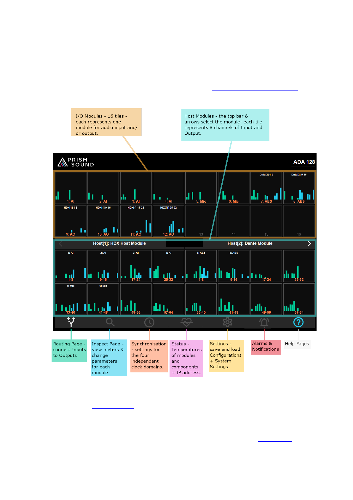
Default screen ......................................................................................................................... 37
The Routing Page................................................................................................................. 38
Description .............................................................................................................................. 38
The Routing procedure. ........................................................................................................... 39
Routing - Step-by-step ............................................................................................................. 39
The Inspect Page.................................................................................................................. 43
I/O Modules ............................................................................................................................ 47
Host Modules .......................................................................................................................... 64
Clocks & Synchronisation Page............................................................................................. 72
Domains Tab............................................................................................................................ 72
Modules Tab............................................................................................................................ 77
Ref In Tab ................................................................................................................................ 78
Ref Out Tab ............................................................................................................................. 80
Status Page .......................................................................................................................... 81
Automatic Fan Controller......................................................................................................... 81
©2021-2023 Audio Squadron Ltd. 4
Download Diagnostics.............................................................................................................. 82
Settings Page ....................................................................................................................... 84
Configurations Tab................................................................................................................... 84
System Tab .............................................................................................................................. 87
Alarms Page......................................................................................................................... 90
Temperature Alarms................................................................................................................ 91
Information Page ................................................................................................................. 91
Help Page ............................................................................................................................ 91
Hardware Reference........................................................................................................................ 92
Considerations when fitting into a 19” rack ................................................................................. 92
Thermal Considerations........................................................................................................... 92
How & where to fit modules........................................................................................................ 92
To fit a new module:-............................................................................................................... 93
D-type connection pin-outs. ........................................................................................................ 97
Power Inlet and Power Switch ................................................................................................... 100
Sync Connections Block ............................................................................................................. 101
DARS sync.............................................................................................................................. 101
Word Clock sync .................................................................................................................... 101
Ref I/O................................................................................................................................... 102
CPU Module .............................................................................................................................. 102
Firmware updates...................................................................................................................... 104
Troubleshooting............................................................................................................................ 108
Browser Issues........................................................................................................................... 108
Technical Topics ............................................................................................................................ 109
Clocking and Jitter ..................................................................................................................... 109
Overkiller................................................................................................................................... 112
Specifications ................................................................................................................................ 113
‘Dream’ ADA-128 Chassis Specifications .................................................................................... 113
‘Dream’ ADA-128 I/O Modules .................................................................................................. 114
‘Dream’ ADA-128 Host Modules ................................................................................................ 118
Supported Sample rates ............................................................................................................ 118

©2021-2023 Audio Squadron Ltd. 5
Power Specifications.................................................................................................................. 118
Appendix A –List of Current Available I/O and Host modules ........................................................ 119
Appendix B –List of third party Audio Interfaces with high numbers of AES I/O............................. 119
Appendix C –Pro Tools | HDX Software Controls........................................................................... 120
Index ......................................................................................................................................... 122
©2021-2023 Audio Squadron Ltd. 6
General Information
ADA-128 Operation Manual Revision History
Rev Date Author Comments
0.90 24th January 2023 S.G. Penn First draft
0.91 8th March 2023 D.S. Rowland Updated footer
0.92 27th March 2023 S.G. Penn v1.1.7.58871618 (incomplete)
0.95 11th April 2023 S.G. Penn v1.1.9.116769065
0.97 10th May 2023 S. G. Penn v1.1.12
0.98 29th May 2023 S.G. Penn v1.1.14
Support Contacts
Audio Squadron Ltd
Unit 1A, Grovemere House,
Lancaster Way Business Park,
Ely, Cambridgeshire,
CB6 3NW, UK
Telephone: +44 1353 648888
Fax: +44 1353 648867
Email: tech.support@prismsound.com
Web: www.prismsound.com
WARNING!
TO PREVENT FIRE OR SHOCK HAZARD DO NOT EXPOSE THIS EQUIPMENT TO RAIN
OR MOISTURE. DO NOT REMOVE THE COVER. NO USER-SERVICABLE PARTS
INSIDE. REFER SERVICING TO QUALIFIED SERVICE PERSONNEL.
Statements of conformity
This equipment has been tested and found to comply with the limits for a Class B digital device,
pursuant to Part 15 of the FCC Rules. These limits are designed to provide reasonable protection
against interference in a residential area. This device generates and uses radio frequency energy
and, if not installed and used in accordance with the instructions, may cause interference to radio or
TV reception. If this unit does cause interference to radio or TV reception, please try to correct the
interference by one or more of the following measures:
a) Reorient or relocate the receiving antenna.

©2021-2023 Audio Squadron Ltd. 7
b) Increase the separation between the equipment and the receiving antenna.
c) Plug the equipment into an outlet on a different circuit from the receiver.
d) If necessary, consult your dealer or an experienced radio or TV technician.
CAUTION: Changes or modifications to this equipment not expressly approved by the manufacturer
could void the user's authority to operate this equipment.
THIS DIGITAL APPARATUS MEETS ALL CLASS B LIMITS FOR RADIO NOISE EMISSIONS AS LAID DOWN
IN THE RADIO INTERFERENCE REGULATIONS OF THE CANADIAN DEPARTMENT OF
COMMUNICATIONS.
CET APPAREIL NUMÉRIQUE RESPECTE TOUTES LES EXIGIENCES APPLICABLES AUX APPAREILS
NUMÉRIQUES DE CLASSE B SUR LE BROUILLAGE RADIOELECTRIQUE EDICTE PAR LE MINISTERE DES
COMMUNICATIONS DU CANADA.
Audio Squadron Ltd. hereby declares that this equipment conforms to the following standards:
EN55103-1, environment category E4
EN55103-2, environment category E4
NOTE: The use of this equipment with non-shielded interface cabling is not recommended by the
manufacturer and may result in non-compliance with one or more of the above directives. All
coaxial connections should be made using a properly screened 75R cable with the screen connected
to the outer of the connector at both ends. All analogue XLR and jack connections should use
screened cable with the screen connected to pin 1 of the XLR connector, or the jack outer, at both
ends.
Trademark Acknowledgements
Pro Tools, Pro Tools | HD, Pro Tools | HDX, Pro Tools | HD Native, Pro Tools | PRE, Digidesign, Avid, DigiLink Mini and
DigiLink are trademarks or registered trademarks of Avid Technology Inc. or its subsidiaries in the United States and/or other
countries.
For the avoidance of confusion, it should be noted that AVID does not endorse or approve use of Prism Sound products that
are compatible with AVID products.
Microsoft and Windows are trademarks of Microsoft Corporation.
Apple, Macintosh, Core Audio and OS X are trademarks of Apple Computer, Inc.
All trademarks acknowledged
© 2021-2023 Audio Squadron Limited. All rights Reserved.
This manual may not be reproduced in whole or part, in any medium, without the written
permission of Audio Squadron Limited.
In accordance with our policy of continual development, features and specifications are subject to
change without notice.

©2021-2023 Audio Squadron Ltd. 8

Prism Sound ADA-128 Operation Manual Revision 1.00
©2021-2023 Audio Squadron Ltd. 9
Introduction
The Prism Sound ‘Dream’ ADA-128 is the latest in the acclaimed range of Prism Sound ‘Dream’ A/D
and D/A professional audio converters which have become widely regarded as the world’s best
sounding converters. Whilst continuing the tried and trusted ‘no compromise’ design philosophy of
previous ‘Dream’ products, the ‘Dream’ADA-128 adds new flexibility, functionality and greater cost-
effectiveness.
The Dream ADA-128 is not just a conversion system, but a high-performance networkable audio
distribution and processing system which meets the most exacting requirements of a recording
studio through to a film sound stage.
Fully Modular
The ‘Dream’ ADA-128 is a 2U chassis that can accommodate up to 20 plug-in modules. These
presently include eight-channel Analogue Input and Output modules and an eight-channel AES3
Module. Four of the slots can accommodate a range of 64-channel Host Modules which include Pro
Tools HDX and Dante Host Modules (and more to come). As well as being able to route analogue
and AES3 I/O to and from Host media, full routing flexibility allows analogue to/from AES3 routing
without use of Host slots, and Host-to-Host bridging.
Every I/O Module, as well as the unit’s built-in Routing Module, has dedicated DSP capability, which
will allow a wide range of future functionality to be added by a simple software download.
A/D & D/A.
The ADA-128 offers accurate, ultra-detailed A/D and D/A conversion providing complete focus of
sound to ensure you're not distracted by colouration while allowing every nuance of a performance
to be heard.
A.D.R.A
Advanced Digital Routing Architecture allows the ADA-128 to provide you with flexible
interconnectivity both internally and externally allowing point to point flexible routing.
QCLOCK
The ADA-128 contains four independent clock generators, each of which can run at a different
sample rate and with a different sync source. The ADA-128’s Host and I/O Modules can be

Prism Sound ADA-128 Operation Manual Revision 1.00
©2021-2023 Audio Squadron Ltd. 10
dynamically assigned to these Clock Domains, allowing multiple workflows (such as separate project
studios or ingest stations) to simultaneously share the resources of a single ADA-128.
SOUND APPLICATIONS
Designed for a multitude of audio application. ADA-128 has the I/O, the tools and the sonic accuracy
to be the converter of choice for Dolby Atmos, Mastering, Dubbing, Archiving, Mixing, Recording and
Post.
A list of the currently available I/O and host options is in Appendix A.
The unit has a large touch-screen on the front panel to allow the user to control settings and
routings as well as displaying level meters for each channel. This control and monitoring may be
replicated in a standard browser running on any computer (or tablet, or smart phone etc.) which is
on the same network as the ADA-128.
Prism Sound ADA-128 Operation Manual Revision 1.00
©2021-2023 Audio Squadron Ltd. 11
Explanation of Concepts.
A ‘Dream’ ADA-128 can be configured with different numbers of I/O and Host modules in many
different ways to suit your work.
Settings, Configurations and Routings are controlled by using a front panel touch-screen display.
Because ADA-128s are likely to be kept in a machine room, and you may wish to control them from a
different location, Remote Control of the settings and routings can be made over a standard
network using any device –computer, smart phone, tablet –that can run a browser.
I/O modules can be Analogue Inputs (Line and/or Mic level) and/or Analogue Outputs, or AES/EBU
digital inputs and outputs. The settings of the I/O modules can be changed in the Inspect Page of the

Prism Sound ADA-128 Operation Manual Revision 1.00
©2021-2023 Audio Squadron Ltd. 12
Control Panel, and in this manual, the functions of each I/O module are described in detail in the I/O
Modules section under ‘Inspect’ in the Software Reference chapter.
Host Modules are for connection to computer based systems, such as Pro Tools | HD systems,
Dante, Ethernet, Ravenna, or AES67 networks, a MADI interface, or some other form of computer
interface, such as USB, Thunderbolt etc. etc. In time more Host and I/O modules will be added to the
range as different formats gather industry support.
When you start working with your ADA-128, you must decide how the available Audio channels are
to be routed –i.e. how Inputs and Outputs connect to the host and/or to each other. With a basic
setup, you may well simply require all the Inputs to be routed to a digital Host module, and all the
outputs from the digital Host. In a setup with multiple Host modules, used perhaps by multiple
studios and computers, the routings and synchronisations may be more complex.
Audio channels on I/O and Host modules may be routed to any of the other I/O or Host modules,
usually in blocks of 8 channels.
The Control Panel gives access to ‘Configurations’–a snapshot of the unit’s settings and routings –
and this way the ADA-128 can be reconfigured, signals re-routed, synchronisations altered etc. by
simply loading a new configuration. Configurations are supplied by the factory for popular usages,
and custom, personalised configurations may also be saved by the user.
As with all digital audio systems, there must be a consideration of how the different equipment in
the studio should be synchronised. ADA-128’s modules can be associated to one of 4 separate Clock
Domains and each Clock Domain can be synchronised independently.
This Manual
…breaks down into, essentially, four sections: -
1) The introduction and outline of the ‘Dream’ ADA-128 system, including this ‘Explanation of
Concepts’article.
2) Quick Start guides –these are step by step guides for getting started quickly, but they are
designed to be very brief, and it is expected that you have some background knowledge of
the concepts and you can find your way around the ADA-128’s (quite intuitive) Control
Panel.
3) Application Section –this goes into much more detail about setting up your system for a
particular type of Host.
4) Reference Section –more than 70% of the manual gives fully detailed descriptions of the
functions of the Control Panel Software, and the ADA-128 hardware and its specifications.
Parts of the Reference guide will be linked from the Quick Starts and Applications to flesh
out the shorter-form descriptions.

Prism Sound ADA-128 Operation Manual Revision 1.00
©2021-2023 Audio Squadron Ltd. 13
Quick Start Guides
Let’s get straight to it and start using the ‘Dream’ ADA-128.
ADA-128 is very customisable and your particular work application may determine exactly how you
need to set it up. We have separate ‘Quick Start’ guides based on the Host card you are using. You
may have more than one Host card, but the Quick Start Guides should get you started with a simple
setup.
The Quick Start Guides are lists of step-by-step bullet points to help a reasonably knowledgeable
engineer to get up and running as quickly as possible. You may need to refer to the reference
sections highlighted if you need more detailed explanations.

Prism Sound ADA-128 Operation Manual Revision 1.00
©2021-2023 Audio Squadron Ltd. 14
Quick Start AES3
The AES I/O module is not strictly considered a ‘Host’ module; it’s an I/O module (but it can be
inserted into a Host module slot). However, a valid way to set up the ‘Dream’ ADA-128 is with all
Analogue Inputs and Outputs routed to and from AES Outputs and Inputs in order to provide high
quality A/D and D/A conversion to a computer system using a digital interface card.
1. Take the ADA-128 out of its box.
2. Consider how to rack mount the ADA-128 unit (See ‘Thermal Considerations’ in the
Hardware section of the Reference Manual) making sure that there is sufficient air flow to
cool it and that there are spaces between other units above and below in the rack.
3. Connect audio connection looms to all your Analogue and AES I/O ports at the back of the
unit. 25-way D-Subs to XLR are wired to Tascam conventions - AES is different from
Analogue. (See ‘D-type connection pin-outs’ in the Hardware Section). If you’re connecting
to other equipment which also uses 25-way D-subs you can use suitable multi-way cables.
4. (Optional but recommended) If you would like to use remote control of the ADA-128 via a
browser, the device running the browser must be on the same network domain as the ADA-
128. Connect a network cable from the back of the ADA-128 to your network.
5. Connect Power using the supplied power to IEC cable. ADA-128 automatically accepts mains
voltages between 90 and 260 Volts A.C. at 50 or 60Hz and so there’s nothing to change for
regional power variations. Switch the ADA-128 on at the rear of the unit. Watch the display
start up –it takes a few seconds.
6. Set up the remote control if required (See ‘Remote Control over network using a browser’
below). The unit’s IP address is shown in the Status page in the Network section at the
bottom left of the screen. Point your browser at the address specified in the ‘GUI’ line….
example …. http://192.168.68.120:2001 (where :2001 is always the port being used).
7. At this point you will need to consider the routing of your audio Inputs and Outputs. This is
set up in the Routing page –See Routing below, and The Routing Procedure for a step-by
step guide to routing. Simply….Click on an Analogue Input module, followed by the AES
module, then OK to route 8 Analogue Ins to AES Outs. Similarly click on an AES module, then
an Analogue Out module and OK, to route to the Analogue Outs.
8. You will need to consider clocking. If you are using Word Clock or i.e. a studio clock to
synchronise your system, then you will need to connect cables first. Then go to the
Synchronisation page of the Control Panel, and set the clocking regime there –‘Clock
Source’.
9. Audio on Analogue inputs should now appear at AES Outputs and AES Inputs should pass
audio to Analogue Outputs.
10. Having customised the routings and clocking of your ADA-128 and it is now working nicely,
make sure to save it as a new configuration file. Go to Settings and in the
‘Configurations’ tab press ‘Save Configuration’, type a name, then ‘Save’.

Prism Sound ADA-128 Operation Manual Revision 1.00
©2021-2023 Audio Squadron Ltd. 15
Quick Start ProTools
This brief quick start guide expects some familiarity with the Avid Pro Tools | HD software itself.
1. Take the ADA-128 out of its box.
2. Consider how to rack mount the ADA-128 unit (See ‘Thermal Considerations’ in the
Hardware section of the Reference Manual) making sure that there is sufficient air flow to
cool it and that there are spaces between other units above and below in the rack.
3. Connect audio connection looms to all your Analogue and AES I/O ports at the back of the
unit. 25-way D-Subs to XLR are wired to Tascam convention, and AES is different from
Analogue. (See ‘D-type connection pin-outs’ in the Hardware Section). If you’re connecting
to other equipment using 25-way sub you can obviously use suitable multi-way cables.
4. Connect DigiLink cables between your host computer’s Pro Tools interface and the ADA-128
DigiLink ports on the Pro Tools | HDX Host Module.
5. You will need to consider synchronisation and any cabling required –one unit in your system
will be Master for Clocks, the rest will be synchronised to it. Connect Loop Sync BNC cables
between ADA-128 and any other I/O units connected your Pro Tools system –with more
than two I/O units in the system you may need to consider daisy-chained sync cables. (See
Pro Tools Connection Diagrams below).
6. (Optional) If you would like to use remote control of some of the ADA-128’s settings via a
browser, the device running the browser must be on the same network domain as the ADA-
128. Connect a network cable from the back of the ADA-128 to your network.
7. Connect Power using the supplied power to IEC cable. ADA-128 automatically accepts mains
voltages between 90 and 260 Volts A.C. at 50 or 60Hz and so there’s nothing to change for
regional power variations. Switch the ADA-128 on at the rear of the unit. Watch the display
start up –it takes a few seconds.
8. Set up the remote control if required (See ‘Remote Control over network using a browser’
below). The unit’s IP address is shown in the Status page in the Network section at the
bottom left of the screen. Point your browser at the address specified in the ‘GUI’ line….
example …. http://192.168.68.120:2001 (where :2001 is always the port being used).
9. At this point you will need to consider the routing of your audio Inputs and Outputs. This is
set up in the Routing page –See Routing below, and The Routing Procedure for a step-by
step guide to routing. Simply….Click on an Analogue Input module, followed by the desired 8
channel block on the PTHDX Host module, then OK to route 8 Analogue Ins to the Pro Tools
software’s Inputs. Similarly click on an 8 channel block on the PTHDX Host module, then an
Analogue Out module and OK, to route to the Analogues Outs.
If you are using AES modules, you will need to consider the setting of the Emulation Mode,
and also it is advisable to keep the routings of any AES modules on a different ‘Virtual’
Interface to the Analogue modules (to ensure correct delay compensations).
10. In the ADA-128 Control Panel’s Clocks page, you will need to set the ADA-128’s Clock Source
to match your synchronisation strategy –in short is the ADA-128 on Internal or External
Sync? This is explained in more detail in the Pro Tools | HDX Application notes.

Prism Sound ADA-128 Operation Manual Revision 1.00
©2021-2023 Audio Squadron Ltd. 16
11. So that the sample rate can be switched within the Pro Tools software, you should enable
Pro Tools Remote Control –go to the Global Inspect page for the PTHDX module, and click
Enabled.
12. Start Pro Tools –the ADA-128 should be seen in Setup /Hardware as one or more ‘HD I/O’
units (ADA-128s are set to emulate and act exactly as if they are standard HD I/O units).
13. Depending on your chosen synchronisation strategy, you may need to set your Clock Source
and Loop Master within the Pro Tools software –go to Setup/Hardware/Clock Source.
14. Audio on Analogue Inputs and Analogue Outputs should now appear at their respective Pro
Tools channels.
15. If you have customised the ADA-128 configuration and it is working nicely, make sure to save
it as a new configuration file. Go to Settings and in the ‘Configurations’ tab press ‘Save
Configuration’, type a name, then ‘Save’.

Prism Sound ADA-128 Operation Manual Revision 1.00
©2021-2023 Audio Squadron Ltd. 17
Applications
In the following section, we will discuss operation with individual Host modules in more detail than
in the Quick Start guides, and this will link to still further information in the Software and Hardware
Reference sections of the manual.
The ‘Dream’ ADA-128 is modular, it can contain multiple host cards and can support multiple clock
domains, which means that a single ADA-128 could be connected to different hosts performing
different tasks simultaneously.
In these sections, we will be using the ADA-128’s Front Panel Touch screen to make settings
changes, and it may also be helpful to attach the ADA-128 to a network and to set up Remote
Control in a browser.
Analogue to / from AES Converter
In its (perhaps) simplest setup you may use the ‘Dream’ ADA-128 as a large channel-count AES to /
from Analogue converter, for instance replacing a rack of ‘Dream’ ADA-8s set up in a similar
configuration.
There are many possible applications for this, from recording, mixing, archiving of multi-channel
material etc.
Using an ADA-128 like this with a computer, the computer would need some kind of multi-channel
digital audio interface.
In recent times devices with multiple AES connections are not so common –many interface devices
have one or two AES or SPDIF I/Os, but very few have larger numbers.
A small selection of computer audio interfaces with multiple AES are listed in Appendix B along with
ideas for using different digital audio interfaces and converting to and from AES3 digital audio.
In a system like this, in order to maximise the number of AES to and from Analogue channels, AES
modules can be fitted into Host module slots –routings can be made freely between Analogue and
AES I/O, no matter which slots the AES cards are fitted into.
Setting up as an AES Converter system
To prepare your ADA-128 for operation as a multi-channel AES converter you will need to consider
the following aspects: -

Prism Sound ADA-128 Operation Manual Revision 1.00
©2021-2023 Audio Squadron Ltd. 18
a) Connection looms –all Analogue and AES connections are on 25-way D-Type connectors that
follow the Tascam convention for pin-outs.
b) You will need to set up Routings in the ADA-128 to ‘connect’ your Analogue Inputs to AES
outs, and AES Inputs to Analogue Outputs.
c) You will need to think about and set up your Synchronisation regime –you will need to
decide which of your digital audio hardware units (including the computer’s interface card)
is to be the Clock Master and which are Slaves. You should then set up the ADA-128’s Clock
Source and any Reference Outs you may wish to use in the ADA-128’s Clocks and
Synchronisation pages.
d) You should check your Analogue Line-up levels to make sure that the ADA-128’s inputs and
outputs are matched to onward audio connections for consoles or outboard gear.
Pro Tools | HDX
Introduction
Pro Tools | HDX Core systems use an Avid-proprietary Interface card / device to connect a computer
(running Pro Tools software) to arrays of audio inputs and outputs.
There are some possible ‘devices’ which can be used for a system like this: -
•Pro Tools | HDX PCIe card
•Pro Tools | HD Native PCIe card or …
•Pro Tools | HD Native Thunderbolt interface.
(For the sake of this manual, we shall refer to any Pro Tools interface card or device as a ‘Pro Tools |
HDX card’ and may abbreviate it to ‘HDX card’. We will abbreviate the ADA-128’s ‘Pro Tools | HDX
module’ as a ‘PTHDX’ module. )
The Pro Tools | HDX PCIe card is equipped with its own DSP to provide processing for software and
plugins as well as connection to Audio Interfaces. The Pro Tools | HD Native options are without
DSP, but offer very low latency input/output and connection to the I/O Interfaces using Avid’s
proprietary ‘DigiLink’ connections.
Multiple Pro Tools | HDX PCIe cards may be used together up to a maximum of three cards; the
‘Native’ cards/Thunderbolt units cannot be combined or used concurrently.
The Pro Tools | HDX Host (PTHDX) module for the ‘Dream’ ADA-128 allows the ADA-128 to be
connected directly and provide audio Inputs and Outputs for an Avid | Pro Tools system with a Pro
Tools | HDX card.
With this setup, Pro Tools users can enjoy the excellent sound quality of the Prism Sound ADA-128.

Prism Sound ADA-128 Operation Manual Revision 1.00
©2021-2023 Audio Squadron Ltd. 19
Thunderbolt or PCIe?
The Pro Tools | HDX PCIe card requires a computer with a PCIe slot. This may be a ‘desktop’
computer box with internal PCIe slots (i.e. an Apple Mac Pro, or a Windows desktop box).
Alternatively, it’s possible to purchase a Thunderbolt connected PCIe Expansion Chassis to house the
HDX PCIe card(s), which may be connected to any computer with a suitable Thunderbolt port.
Many companies can supply this kind of Expansion chassis –Magma and Sonnet are amongst those.
When purchasing this, you should double-check for compatibility with the Pro Tools | HDX PCIe card.
Setting Up for Pro Tools operation
There are a number of factors to consider when setting up a Pro Tools system for use with the ADA-
128.
1. The computer needs a Pro Tools | HDX PCIe card (or HD Native card or unit).
2. The ADA-128 requires a PTHDX module.
3. DigiLink Mini cables are required to connect the ADA-128’s PTHDX module to the Pro Tools |
HDX card. You will need one Digilink cable if your channel count is less than or equal to 32 in,
32 out, or two for between 32 and 64 channels.
4. In the ADA-128 you must set up routings to connect digital audio from the PTHDX module to
the outside world via the ADA-128’s audio I/O modules.
5. You should enable Pro Tools Remote Control on the ADA-128 so that some settings can be
controlled by the Pro Tools software.
6. If you have other hardware attached to your system –either Pro Tools | HD I/O units
connected to the HDX cards alongside the ADA-128, or else other digital audio hardware
used for processing etc. then all units must be synchronised –you will need to connect them
together with Sync cables, and you will need to consider the Sync settings for the ADA-128,
the Pro Tools software and any other hardware.
7. You should check your Analogue Line-up levels to make sure that the ADA-128’s inputs and
outputs are matched to onward audio connections for consoles or outboard gear.
PTHDX Module and Emulation
When the ADA-128 is fitted with a single Pro Tools | HDX Host (PTHDX) module, the ADA-128 can
support up to 64 channels of audio Input and 64 channels of Output for the Pro Tools system.
In order that the operation with Pro Tools is seamless, the ADA-128 ‘emulates’ Avid’s own Pro Tools
| HD I/O interfaces, and (when Pro Tools Remote Control is enabled) control of settings such as
sample rates and other parameters is from within the Pro Tools software.

Prism Sound ADA-128 Operation Manual Revision 1.00
©2021-2023 Audio Squadron Ltd. 20
With the PTHDX module connected via DigiLink Mini cables to the system’s Pro Tools | HDX card, the
Pro Tools software will see the ADA-128 as up to 4 separate ‘Virtual Interface’ units which will show
in Pro Tools software as HD I/O units, allowing 16 channels of I/O per ‘Virtual Interface’/ HD I/O unit.
For those that are familiar with earlier Prism Sound I/O units that supported Pro Tools connection,
such as Atlas, Titan or ADA-8XR, the concept is similar. However, you can forget about the older
regime of ‘Main’ and ‘Sub’ units –thankfully, this complication does not apply to the ADA-128.
For channel counts that exceed 64 in or out (for instance you may require your ADA-128 to be fitted
with, say, 112 inputs and 16 outputs) you can fit an extra PTHDX module to your ADA-128. You will
also need another Pro Tools | HDX PCIe card to support the higher channel count and to connect via
DigiLink to the extra PTHDX module.
DigiLink Connections
Note that the ADA-128 has ‘DigiLink Mini’connections, like modern Pro Tools | Core system cards.
For the sake of this document, any mention of ‘DigiLink’ refers to ‘DigiLink Mini’ connections.
Each ADA-128 PTHDX module has 2 x DigiLink ports. Each Pro Tools | HDX card has 2 x DigiLink ports.
Each DigiLink port supports up to 32 channels of Input and Output and thus a maximum of 64 I/O is
allowed for one HDX card (and one PTHDX module).
From the Pro Tools perspective, whatever I/O modules are fitted to the ADA-128, the ADA-128
occupies 32 channels (with one DigiLink connected) or 64 channels (with two DigiLinks connected),
and will show as 2 x 16 channel units or 4 x 16 channel units.
Some Avid HD I/O units (and Prism ADA-8XR and Titan/Atlas) provide ‘Expansion’ DigiLink ports to
allow further I/O units to be ‘daisy-chained’ on the DigiLink bus. The DigiLink Ports on the ADA-128
are direct connection ports, like those on the HDX/HD Native card, and do not provide any daisy-
chaining facility.
ADA-128 Modules’ Clock Domains
If this is a factory set unit then this step may not be necessary, but if the ADA-128 has had any
significant customisation, before setting up any audio Routings and Sync settings, you may wish to
reload a Configuration or check that the I/O modules that you wish to use with the PTHDX module
are all on the same Clock Domain.
Click on the icon on the ADA-128’s control panel bottom toolbar, and then click on the
MODULES tab: -
Table of contents
Other Prism Sound Media Converter manuals


Popular Media Converter manuals by other brands


DirekTronik
DirekTronik 20100547 Operation manual

Doepke
Doepke SITU Installation and operating manual

Cross Technologies
Cross Technologies 2117-7172 instruction manual

ATZ
ATZ HDMI-EN101 instructions

IS5 COMMUNICATIONS
IS5 COMMUNICATIONS iSC2 Series user manual

Pro-Ject Audio Systems
Pro-Ject Audio Systems DAC Box DS Instructions for use


