Prism Sound ADA-8XR User manual

ADA-8XR Multi-channel A/D D/A Converter
Operation Manual

Prism Sound ADA-8XR Multi-channel A/D D/A Converter Operation Manual - Revision 1.
© Prism Media Products Limited, 2 1-2 4 Page 1.2
Operation Manual Revision History
Rev Date Author Comments
1. 4th December 2 4 Ian Dennis Initial release with 2. firmware
Support Contacts
Prism Media Products Limited Prism Media Products Inc
William James House 21 Pine Street
Cowley Road Rockaway
Cambridge CB4 WX NJ 7866
UK USA
Telephone: +44 1223 424988 Telephone: +1 973 983 9577
Fax: +44 1223 425 23 Fax: +1 973 983 9588
Email: tech.support@prismsound.com
Web: http://www.prismsound.com
Or contact your local Prism Sound distributor as detailed on the website.
Trademar Ac nowledgements
Digidesign, Pro Tools, Pro Tools 24|MIX, 888|24 I/O, Pro Tools|HD, 192 I/O, 96 I/O, SYNC I/O and DigiLink are
trademarks of Digidesign, a division of Avid Technology Inc.
Direct Stream Digital, DSD, MAC-DSD, SuperMAC and the DSD logo are trademarks of Sony Corporation.
Super Audio CD, SACD and the SACD logo are joint trademarks of Sony Corporation and Philips Electronics N.V.
All trademarks acknowledged
© 2 1-2 4 Prism Media Products Limited. All rights reserved.
This manual may not be reproduced in whole or part, in any medium, without the written
permission of Prism Media Products Limited.
In accordance with our policy of continual development, features and specifications are
subject to change without notice.

Prism Sound ADA-8XR Multi-channel A/D D/A Converter Operation Manual - Revision 1.
© Prism Media Products Limited, 2 1-2 4 Page 1.3
WARNING!
TO PREVENT FIRE OR SHOCK HAZARD DO NOT EXPOSE
THIS EQUIPMENT TO RAIN OR MOISTURE. DO NOT
REMOVE THE COVER. NO USER-SERICEABLE PARTS
INSIDE. REFER SERVICING TO QUALIFIED SERVICE
PERSONNEL.
Statements of Conformity
This equipment has been tested and found to comply with the limits for a Class B digital device, pursuant to Part 15
of the FCC Rules. These limits are designed to provide reasonable protection against interference in a residential
area. This device generates and uses radio frequency energy and, if not installed and used in accordance with the
instructions, may cause interference to radio or TV reception. If this unit does cause interference to radio or TV
reception, please try to correct the interference by one or more of the following measures:
a) Reorient or relocate the receiving antenna.
b) Increase the separation between the equipment and the receiving antenna.
c) Plug the equipment into an outlet on a different circuit from the receiver.
d) If necessary, consult your dealer or an experienced radio or TV technician.
CAUTION: Changes or modifications to this equipment not expressly approved by the manufacturer could void the
user’s authority to operate this equipment.
THIS DIGITAL APPARATUS MEETS ALL CLASS B LIMITS FOR RADIO NOISE EMISSIONS AS LAID DOWN IN
THE RADIO INTERFERENCE REGULATIONS OF THE CANADIAN DEPARTMENT OF COMMUNICATIONS.
CET APPAREIL NUMÉRIQUE RESPECTE TOUTES LES EXIGIENCES APPLICABLES AUX APPAREILS
NUMÉRIQUES DE CLASSE B SUR LE BROUILLAGE RADIOELECTRIQUE EDICTE PAR LE MINISTERE DES
COMMUNICATIONS DU CANADA.
Prism Media Products Ltd hereby declares that this equipment conforms to the following standards:
EN551 3-1, environment category E4
EN551 3-2, environment category E4
NOTE: The use of this equipment with non-shielded interface cabling is not recommended by the manufacturer and
may result in non-compliance with one or more of the above directives. All coaxial connections should be made
using a properly screened 75Ω cable with the screen connected to the outer of the connector at both ends. All XLR
connections should use a screened twisted pair cable with the screen connected to pin 1 of the XLR connector at
both ends. In the case of the digital XLR connections this cable should be of 11 Ω impedance.

Prism Sound ADA-8XR Multi-channel A/D D/A Converter Operation Manual - Revision 1.
© Prism Media Products Limited, 2 1-2 4 Page 1.4
Contents
1 Introduction ............................................................................ 6
1.1 Functionality ................................................................................................................ 6
1.2 Modularity.................................................................................................................... 7
1.3 Firmware Updates....................................................................................................... 7
1.4 Organization of these Manuals ................................................................................... 7
2 Getting Started ....................................................................... 8
2.1 Connecting the ADA-8XR ........................................................................................... 8
2.2 Configuring the ADA-8XR ........................................................................................... 8
3 Layout ................................................................................... 10
3.1 Front Panel................................................................................................................ 1
3.2 Rear Panel ................................................................................................................ 11
4 Philosophy of Operation...................................................... 12
4.1 Two Paths ................................................................................................................. 12
4.2 Menus or dedicated controls?................................................................................... 12
4.3 Monitor, Mimic, Meter and Menu Panels .................................................................. 12
4.4 Two-channel Monitor................................................................................................. 13
4.5 Configuration / Stores ............................................................................................... 13
4.6 Warning conditions.................................................................................................... 14
5 Control Panel Operation...................................................... 15
5.1 Mimic Panel............................................................................................................... 15
5.1.1 Source box......................................................................................................... 15
5.1.2 Decode box........................................................................................................ 16
5.1.3 Process box ....................................................................................................... 17
5.1.4 Dither/Encode box ............................................................................................. 17
5.1.5 Dest box............................................................................................................. 18
5.1.6 Sync Source/Sample Rate box.......................................................................... 18
5.2 Meter Panel............................................................................................................... 2
5.3 Monitor Panel ............................................................................................................ 21
5.4 Menu Panel ............................................................................................................... 22
6 Adjustments and Upgrades................................................. 23
6.1 Changing the mains voltage or fuse ......................................................................... 23
6.2 Adding I/O Modules................................................................................................... 24
6.3 Upgrading the firmware............................................................................................. 24
7 Technical Bac ground ......................................................... 25
7.1 Synchronization and jitter.......................................................................................... 25
7.1.1 Background........................................................................................................ 25
7.1.2 Why are good clocks so rare? ........................................................................... 25
7.1.3 Analysis of sampling jitter .................................................................................. 25
7.1.4 Listening experience.......................................................................................... 26
7.1.5 Synchronization and the ADA-8XR.................................................................... 26
7.2 Extended sample rates and Split96 interfacing ........................................................ 26
7.2.1 What are ‘extended’ sample rates? ................................................................... 26
7.2.2 What is the use of extended sample rates? ...................................................... 27
7.2.3 Interfacing extended sample rates..................................................................... 27
7.2.4 Extended sample rates in the ADA-8XR ........................................................... 28
7.3 Wordlength, dithering and Prism Sound SNS (Super Noise Shaping) ..................... 28
7.3.1 Truncation and dithering .................................................................................... 28
7.3.2 Noise shaping .................................................................................................... 29
7.3.3 Wordlength and the ADA-8XR........................................................................... 29
7.4 Prism Sound MR-X and DRE encoding processes .................................................. 31
7.4.1 Prism Sound MR-X ............................................................................................ 31
7.4.2 Using Prism Sound MR-X with the ADA-8XR.................................................... 32
7.4.3 Prism Sound DRE: ‘Dynamic Range Enhancement’......................................... 33
7.4.4 Using Prism Sound DRE with the ADA-8XR ..................................................... 33
7.5 Prism Sound Overkiller ............................................................................................. 34

Prism Sound ADA-8XR Multi-channel A/D D/A Converter Operation Manual - Revision 1.
© Prism Media Products Limited, 2 1-2 4 Page 1.5
7.6 Sample-rate conversion and Prism Sound SSRC .................................................... 34
7.7 References................................................................................................................ 35
8 Specifications....................................................................... 36
8.1 Physical..................................................................................................................... 36
8.2 Synchronization......................................................................................................... 36
8.3 Monitor ...................................................................................................................... 37
8.4 Meters ....................................................................................................................... 37
8.5 DSP........................................................................................................................... 37
9 Glossary ............................................................................... 38

Prism Sound ADA-8XR Multi-channel A/D D/A Converter Operation Manual - Revision 1.
© Prism Media Products Limited, 2 1-2 4 Page 1.6
1 Introduction
The ADA-8XR is the latest in the acclaimed range of Prism Sound ‘Dream’ A/D and D/A
converters which have become widely regarded as the world’s best sounding converters.
Whilst continuing the tried and trusted ‘no compromise’ design philosophy of previous ‘Dream’
products, the Dream ADA-8XR adds a new dimension in flexibility, functionality and cost-
effectiveness:
• Eight channels of high-performance 24-bit A/D conversion;
• Eight channels of high-performance 24-bit D/A conversion;
• Sample rates up to 192kHz;
• Modular digital I/O options include popular interface standards and direct workstation
connections;
• Two-channel Monitor section follows channel pairs or a mix of all channels;
• Prism Sound ‘Overkiller’ progressive limiting of each A/D channel;
• Prism Sound ‘Super-Noise Shaping’ on each channel;
• Precise and repeatable software-controlled analogue input and output line-up levels;
• Eight-channel assignable bargraph meter array with over-detection;
• Renowned Prism Sound jitter-rejecting PLL technology and low-jitter master clock;
• Flexible synchronization options, including sync to AES11, wordclock or video sync;
• Flexible routing allows creation of D-D processing Paths for processing or format
conversion;
• Prism Sound ‘MR-X’ bit-splitting allows extended wordlengths and sample rates on 16-bit
media;
• Prism Sound ‘DRE’ allows extended wordlength performance on 16-bit stereo media;
• Optional DSP expansion facility for extended processing features, including synchronous
sample-rate conversion;
• Modular architecture allows special configurations: e.g. 16-channel D/A or A/D unit;
• Comprehensive store system for fast-access factory and user presets;
• Unique ‘Access button’ layout combines flexibility of menus with speed of dedicated
controls;
• Modular architecture provides future-proofing: A/D conversion, D/A conversion, DSP, digital
interfacing and utility hardware can all be individually upgraded;
1.1 Functionality
The ADA-8XR provides eight channels of high-resolution, high-sample-rate A/D and D/A
conversion with a variety of processing and interfacing functions, plus a two-channel Monitor
with both analogue and digital outputs.
A/D and D/A Paths can be independently synchronized at 32, 44.1, 48, 88.2, 96, 176.4 or
192kHz sample rates. Sync sources can be Local, WCK, AES11 or DI (one of the digital
inputs), and can be at a different rate from the Path’s sample rate if required. Wordlengths of
16, 2 and 24 bits are supported.
Digital output wordlength is managed by flat re-dithering, or by applying one of the family of
industry-standard Prism Sound SNS noise shaping algorithms. Bit-splitting using the Prism
Sound MR-X system (as implemented on the Prism Sound MR-2 24T interface adapter and
licensed equipment from other manufacturers) is built-in, so that 2 -bit and 24-bit recordings
at up to 96kHz can be made and replayed using 16-bit, low-sample-rate recorders. Encoding
and decoding of Prism Sound’s DRE process (extended wordlength recording on 16-bit media
without sacrificing tracks) is also included. Digital I/O for high sample rates can be in 1-wire
or 2-wire (‘Split96’) format.
Analogue inputs can be individually aligned in software for dBFS levels of +5dBu to +24dBu
in .5dBu steps, with ±.5dB trim in . 5dB steps. The Prism Sound ‘Overkiller’ progressive
limiter feature is selectable per analogue input channel to allow louder tape levels by control

Prism Sound ADA-8XR Multi-channel A/D D/A Converter Operation Manual - Revision 1.
© Prism Media Products Limited, 2 1-2 4 Page 1.7
of transients. Analogue outputs can also be individually aligned for dBFS levels of +5dBu to
+24dBu in .5dBu steps, with ±.5dB trim in . 5dB steps.
A two-channel Monitor is provided which can be attached to either the A/D or D/A Path; it can
monitor either adjacent-channel pairs, or a mix of any or all of the channels, with individual
gain and pan settings. The Monitor has both analogue (line and headphone) and digital
outputs.
Digital-to-digital Paths can be set up for dithering/noise-shaping, or MR-X/DRE
encoding/decoding, and/or converting between different interface formats.
1.2 Modularity
The ADA-8XR is modular in respect of both its hardware and software. Throughout the life of
the product, new software features and support for new hardware options will be added
through firmware updates which will be distributed on disk and via the Internet.
Although the standard ADA-8XR as summarised above provides eight channels of A/D and
eight channels of simultaneous D/A conversion with a variety of available digital I/O options,
many custom configurations are possible. For example, the ADA-8XR can be supplied as
A/D-only or D/A-only at a cost saving, or with two A/D or D/A Modules for sixteen-channel
operation. A two-frame 8-in-24-out setup is a popular and cost-effective choice for DAW
users.
Another advantage of the modular construction of the ADA-8XR is that future improvements
in technology can be incorporated; for example new A/D converter devices, D/A converter
devices, DSP chips, digital I/O standards can all be accommodated by replacing only the
relevant Module.
1.3 Firmware Updates
The ADA-8XR firmware is stored within the unit in a flash memory which can be updated from
a floppy disk or from the Internet. Details of how to perform the upgrade are in section 6.3.
1.4 Organization of these Manuals
The ADA-8XR operators’ literature is organised as three separate volumes:
• Operation Manual (this volume) which covers the general principles of operation;
• Firmware Reference which provides operating details of the latest firmware revision;
this volume can be updated in the event of a firmware upgrade;
• Module Reference which contains information about all available analogue and
digital I/O Modules; this volume can be updated to cover new I/O Modules;

Prism Sound ADA-8XR Multi-channel A/D D/A Converter Operation Manual - Revision 1.
© Prism Media Products Limited, 2 1-2 4 Page 1.8
2 Getting Started
This section is intended to get you going quickly, without the need to read the entire
Operation Manual. This is quite feasible if your application is fairly ‘standard’; if not, you may
need to refer to other parts of the manual to get exactly what you need.
If your ADA-8XR is to be used with a direct workstation interface, such as Pro Tools, please
refer to the appropriate ‘Getting Started’ section in the Module Reference (volume 3).
2.1 Connecting the D -8XR
First, check that the line voltage setting matches your local voltage; if not change it by
reorienting the voltage selector in the power inlet on the rear of the unit. Two ranges are
selectable: 18 -25 VAC or 9 -125VAC. Details of how to switch between ranges are in
section 6.1.
Connections to the analogue inputs and outputs are via panel-mounted XLR connectors.
Connections to digital inputs and outputs may require the use of a breakout cable (supplied)
according to the formats fitted to your unit. Direct connection to a workstation may require the
use of the workstation manufacturer’s cable. Refer to the appropriate section in the Module
Reference for connection details and example diagrams.
Analogue Monitor outputs are on RCA (phono) sockets; stereo digital Monitor out is on BNC
(RCA/phono adapter included); AES11 ref sync I/O are on XLRs; wordclock ref sync I/O are
on BNCs; serial comms (jumpered for RS-232) is on DB9 male.
Plug in the unit and switch on the power switch which is integral to the power inlet. The
ADA-8XR should briefly light all LEDs, then settle into its default setup with the level screen
displayed on the LCD display. The unit can thereafter be turned off and on using the
‘Standby’ key in the top left-hand corner of the front panel.
2.2 Configuring the D -8XR
The user-interface of the ADA-8XR is a ‘three-tier’ system. If your application is fairly
standard, you will probably be able to load a ‘Factory Store’, and be up and running straight
away. There may be a few changes which you need to make to the loaded Store, which you
can most easily do using the blue ‘Access’ buttons to take you straight to the Menus you
need. If your application is unusual in its details, you may need to navigate the Menu system
manually.
First, have a look at the available ‘standard’ Factory Stores at the end of the Firmware
Reference. These apply to most non-workstation applications. If you’re using a dedicated
Workstation I/O Module, look instead at the Factory Stores section for that Module in the I/O
Module Reference. Hopefully one of the Factory Stores will be either exactly what you need,
or close to it.
Select the most appropriate Factory Store by pressing the ‘Bank’ button at the bottom left of
the Menu Panel until the desired Bank of Stores is shown in the LCD display. Then press the
desired Store number button. At this point, the name and number of the desired Store should
be displayed, along with the message: “Load?”. Press the ‘Enter/Accept’ key to load the
Store.
If the Store you loaded requires further modification, the easiest way to do this is to use the
blue Access buttons which are distributed over the ADA-8XR’s Front Panel. The Access
buttons on the Mimic Panel (block diagram) area are the most likely to be useful. Using the
‘Path’ select button in the top left-hand corner of the Mimic Panel, choose the Path who’s

Prism Sound ADA-8XR Multi-channel A/D D/A Converter Operation Manual - Revision 1.
© Prism Media Products Limited, 2 1-2 4 Page 1.9
settings you want to modify. Normally Path 1 is configured as the A/D Path and Path 2 as the
D/A Path, although other variations are possible – check that you are dealing with the desired
Path by observing the signal flow indicated by the LEDs on the Mimic Panel in each of the
states of the ‘Path’ selector button.
Choose the appropriate Access button to take you to the first parameter you want to alter.
For example, if you want to change something to do with the analogue input of an A/D Path,
press the Access button in the ‘Source’ box. This action takes the Menu Panel (with the LCD
display) directly to the cluster of Menus which deal with the analogue inputs. Pressing the
SOURCE Access button again moves to the next analogue-input-related Menu and so on, in
a cyclic fashion. When you have found the Menu you want, you should be able to alter the
desired parameter using the Menu keys (in combination with the Channel Select buttons at
the bottom of the Meter Panel if the parameter must be altered per-channel).
If you can’t find how to access the desired parameters, refer to the Firmware Reference. If
the parameters are obscure, you may need to navigate the Menu system manually without
the help of the Access buttons.
Finally, you should be able to check the correct operation of the ADA-8XR in system by using
the eight bargraph meters on the Meter Panel, and perhaps also the two-channel Monitor
feature, which is controlled from the Monitor Panel at the left-hand side of the unit. Note that
both of these Panels are also assignable to either of the two eight-channel Paths with their
own [Path] selector buttons.
Prism Sound ADA-8XR Multi-channel A/D D/A Converter Operation Manual - Revision 1.
© Prism Media Products Limited, 2 1-2 4 Page 1.1
3 Layout
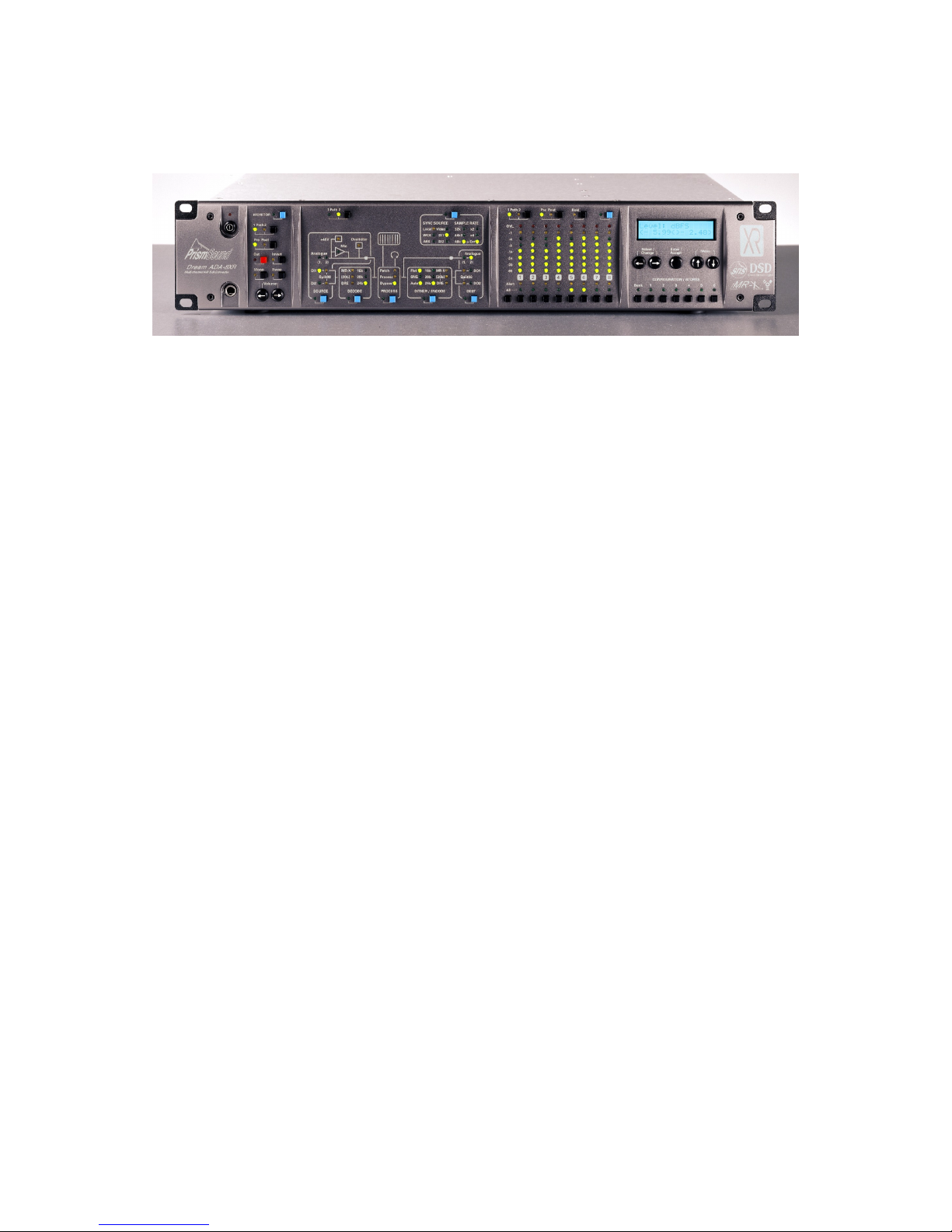
3.1 Front Panel
The front panel of the ADA-8XR contains four divided panels, from left to right:
The Monitor Panel controls and displays all parameters of the two-channel Monitor.
The Mimic Panel controls and displays all parameters of the routing and processing of the two
eight-channel audio Paths through the ADA-8XR.
The Meter Panel contains eight LED bargraphs which can be switched to meter either of the
two eight-channel Paths, as well as a row of Channel Select buttons, which are used to apply
controls to one or more selected channels, or to all eight channels using the ‘All’ button.
On the right-hand side is the Menu Panel, which contains the LCD display and navigation
keys for the menu system, through which all parametric adjustments are made. Blue Access
buttons, distributed over the other three panels, provide short-cuts into those parts of the
menu system related to their positions. Below the menu controls are the buttons for the
Configuration / Store system, which allows factory and user-defined setups to be instantly
loaded.
At the extreme left-hand side of the front panel are the ‘Standby’ key (which is used to switch
the ADA-8XR in and out of Standby power mode) and, below, a headphone socket for the
two-channel Monitor.

Prism Sound ADA-8XR Multi-channel A/D D/A Converter Operation Manual - Revision 1.
© Prism Media Products Limited, 2 1-2 4 Page 1.11
3.2 Rear Panel
The rear panel of the ADA-8XR is arranged, from left to right when viewed from the rear, as
follows:
The mains inlet comprises an inlet socket for the IEC mains lead (appropriate regional
version, provided), mains switch, and two-way voltage selector and fuse holder. For details of
how to change the voltage selector, see section 6.1.
To the right of the mains inlet are two large Module Slots for Analogue I/O Modules. The
upper slot is referred to as Analogue I/O Slot #1, or AIO1 in the front-panel legends and
menus. Inputs on Analogue Module #1 are referred to as AI1, outputs as AO1. The lower
slot is Analogue I/O Slot #2, with similar nomenclatures.
To the right of the Analogue I/O Slots are two small Module Slots for Digital I/O Modules. The
upper slot is referred to as Digital I/O Slot #1, or DIO1 in the front-panel legends and menus.
Inputs on Digital Module #1 are referred to as DI1, outputs as DO1. The lower slot is Digital
I/O Slot #2, with similar nomenclatures.
On the extreme right-hand side is the Utility Module, which contains a variety of input and
output connectors for Reference Sync, analogue and digital Monitor, and serial
communications.
Details of all available Analogue and Digital I/O Modules, including the Utility Module, are in
the Module Reference.

Prism Sound ADA-8XR Multi-channel A/D D/A Converter Operation Manual - Revision 1.
© Prism Media Products Limited, 2 1-2 4 Page 1.12
4 Philosophy of Operation
4.1 Two Paths
The ADA-8XR has two Paths each comprising eight channels; these are typically an A/D Path
and a D/A Path (but not necessarily so). The Monitor, Mimic and Meter panels each have a
‘Path’ selector button so that their function can be swapped between the Paths. The ‘Path’
selector buttons on these panels are independent, so you can monitor one Path while
metering the other, for instance. The Monitor and Meters can be positioned ‘Pre’ or ‘Post’ the
Path’s Processing function (if any), but in systems without the Processing suite installed, or
with it turned off, these buttons don’t change anything.
4.2 Menus or dedicated controls?
The ADA-8XR has a novel operating philosophy. We were concerned that the unit should be
simple to use, even though its flexibility and modularity mean that it has very many controls,
and will have even more in the future.
We know that nobody likes menus - it takes a long time to find what you need. On the other
hand, a button and a display for everything wouldn’t fit on the front panel, and would be
confusing - and we couldn’t add new features in later software releases.
So the ADA-8XR control surface is based on four panels; from left to right the Monitor, Mimic,
Meter and Menu panels (all alliteration absolutely accidental).
4.3 Monitor, Mimic, Meter and Menu Panels
In the Menu panel, you will find a huge menu (details of which are included in the
accompanying Firmware Reference) and the Configuration/Store buttons. It is possible to do
nearly anything through the menu system, but you have to know where to look. This is where
the other panels come in.
The Mimic panel shows a diagram of a ‘Path’ through the ADA-8XR - each Path is actually
eight audio channels in parallel, so the Mimic panel actually only shows one eighth of a Path.
The A/D Path, for example, (usually Path 1) shows an analogue input, connected through
some processing, past a monitoring and metering point, through some ‘encoding’ and out
through a digital output. Naturally, there are countless settings which affect this Path buried
in the menu system.
On the Mimic panel are a selection of blue Access buttons, each one conveniently located in
one of the functional areas of the Mimic. If you press an Access button, you immediately
attract the attention of the Menu panel to the particular menu which controls that function (and
the nearby blue LED lights to show that that is happening).
Actually, there may be several menus which apply to that Access button; if the first menu isn’t
the right one, press the Access button again and you can cycle round the small number of
relevant menus. If you use the same menu a lot, don’t worry - next time you use that Access
button, you go straight to the menu you were using last time you were in that Access group.
The Monitor and Meter panels also have an Access button which are used to get to their parts
of the menu system fast.
In the Meter panel, under each channel’s meter, is a Channel Select button; normally, this is
used to monitor that pair of channels (or to select or deselect the channel if the Monitor is in

Prism Sound ADA-8XR Multi-channel A/D D/A Converter Operation Manual - Revision 1.
© Prism Media Products Limited, 2 1-2 4 Page 1.13
Mix mode). But in menus where settings need to be made ‘per channel’, these buttons take
on that function whilst that menu is selected.
4.4 Two-channel Monitor
Apart from its two eight-channel Paths, the ADA-8XR has a separate two-channel Monitor
which can be assigned to either Path. It has a headphone output, as well as analogue and
digital ‘line outputs’. It has the usual Cut, Invert, Swap and Mono functions, along with a
volume control (which can be switched out if you want to use an external control for the line
volume). Inserting the headphones can be made to mute the line outputs if required.
The Monitor can be set to ‘Pairs’ or ‘Mix’ mode. In Pairs mode, it simply monitors adjacent
pairs of channels (odd to the left, even to the right) as selected by the Channel Select buttons.
In Mix mode, a mix of any or all of the eight channels in the Path can be built up, each with its
own gain and pan. You can switch between separately adjusted mixes for each Path.
4.5 Configuration / Stores
These buttons are used to change the entire setup of the ADA-8XR between preset
configurations for different tasks. There are four ‘Banks’ each containing six entire Stores of
the ADA-8XR state, thus a total of 24 stores are available. Each store can have a name of up
to 16 characters to ease identification.
Pressing either the ‘Bank’ button or one of the Store number buttons (‘1’..’6’) attracts the
attention of the LCD display to the Configuration/Store system. The name of the currently-
selected Store is displayed on the top line, with the Bank/Store number shown below. The
various stores can be previewed by pressing the Store number buttons (‘1’..’6’), and the Bank
can be advanced by pressing the Bank button. The currently-selected Store’s LED flashes.
The LCD is returned to it’s normal operation by re-pressing the flashing Store button (‘1’..’6’),
or by pressing the ‘Menu’ keys (‘↑’ or ‘↓’) or by pressing a blue Access button. Normal
operation is also resumed by the expiry of the menu timeout, if enabled.
The previewed store can be adopted (‘loaded’), unless empty, by pressing Enter/Accept.
Alternatively, it can be over-written (‘saved’) or cleared by using the ‘Select/Change’ keys (‘←’
or ‘→’) to select the required function, followed by ‘Enter/Accept’. Clearing a Store requires a
confirmation step; saving requires the store name to be confirmed or edited, followed by a
confirmation step.
When a Store has been loaded, that Store’s button remains illuminated (until any settings are
manually changed) to indicate that the Store is current.
At the time of delivery, some of the Stores in the first Banks contain ‘factory’ preset stores
covering a range of basic setups (depending on the I/O Modules fitted to the unit), and the
remaining Stores are empty. However, the factory-programmed stores are essentially the
same as others in that they can be user-programmed if required. If, after reprogramming, it is
desired to return these Stores to their factory default settings, this can be achieved through
the Preferences menu. The Factory Default Stores loaded will reflect the I/O Modules fitted at
the time of the reload.
The user can select whether or not analogue I/O line-up gains and trims, and the state of the
Monitor are to be recalled with Stores, or not, by using submenus within Preferences.

Prism Sound ADA-8XR Multi-channel A/D D/A Converter Operation Manual - Revision 1.
© Prism Media Products Limited, 2 1-2 4 Page 1.14
4.6 Warning conditions
It is possible to set operating parameters in the ADA-8XR which are mutually conflicting, or
which cannot be met for other reasons. For instance if the analogue outputs are assigned to
both Paths, or if an external reference sync is specified but is not connected, then the
ADA-8XR must deal with the resulting situation.
In these cases, warnings are generated. Warnings are indicated by a flashing LED, and
possibly the solid illumination of an additional LED. For example, in the case of an
unconnected external reference sync, local sync will be automatically substituted and this
state will be shown by the ‘Local’ LED being lit and the LED of the intended external sync
being flashed.
In general, solidly lit LEDs indicate what is actually happening, and flashing LEDs indicate
what has been requested but cannot be implemented.
If any warnings are active, a row of flashing exclamation marks are shown at the right-hand
side of the LCD display when it is in the default ‘level’ display mode (‘!!!→’). Pressing the
right ‘Select/Change’ key (‘→’) enters the Warnings screen, where all the current warnings are
flashed in turn on the bottom line of the LCD. To return to the normal ‘Level’ display, press
the left ‘Select/Change’ key (‘←’).

Prism Sound ADA-8XR Multi-channel A/D D/A Converter Operation Manual - Revision 1.
© Prism Media Products Limited, 2 1-2 4 Page 1.15
5 Control Panel Operation
5.1 Mimic Panel
The Mimic panel is the key to understanding and controlling the flow of signals through the
ADA-8XR. At any one time, it shows the flow of signals through one of the ADA-8XR’s two
Paths, from the assigned source ports, through any assigned processing functions, through to
the assigned destination ports.
The ‘Path’ selector button in the top left-hand corner of the panel assigns its function to either
Path 1 or Path 2. Path 1 is usually the A-D Path, and Path 2 the D-A Path, in most standard
A/D-D/A configurations, but this is flexible.
The remaining controls and indicators on the Mimic Panel are arranged in an array of
functionally separate boxes, as described below. Each of these functional boxes has a blue
Access button, which takes the ADA-8XR’s menu system directly to the small group of menus
which apply to that box’s function; pressing the Access button repeatedly cycles through the
menus specific to that box. For details of these functions, see the Firmware Reference. Note
that the menus reached by pressing the Access buttons can also be reached (but not so
quickly or conveniently) by navigating the menu system in the normal way. An Access
button’s LED is lit whenever one of its associated menus is active, even if that menu was not
activated by the Access button.
5.1.1 Source box
The Source box indicates which port(s) are assigned as the inputs to the selected Path, and
displays other input-related parameters. The Source box’s Access button attracts the
attention of the Menu panel immediately to the small group of menus that control source-
related parameters. These include assignment of the source ports themselves, adjustment of
analogue input gains (if an analogue source port is assigned) etc. For details of these menus,
see the Firmware Reference.
The green LEDs at the left-hand side of the box show which input ports have been assigned
to the Path. These comprise Analogue Module Slot 1 or 2 inputs, or Digital Module Slot 1 or 2
inputs. The ‘Split96’ indicators show when digital inputs are being used in a ‘two wire’ mode
whereby a single high-rate channel is being carried on a normally-two-channel interface.

Prism Sound ADA-8XR Multi-channel A/D D/A Converter Operation Manual - Revision 1.
© Prism Media Products Limited, 2 1-2 4 Page 1.16
Note that more than one source LED can be lit; this might happen when two Digital I/O
Modules are ‘cascaded’ in Split96 mode to provide all eight inputs, or when the ‘Input
Selection Mode’ is set to ‘Channel’, allowing each channel’s input to be chosen from more
than one assigned port (see the Firmware Reference). A source LED which is flashing
indicates that a selection has been requested which the ADA-8XR firmware cannot
accomplish, for example a source port may have been assigned which has already been
assigned to the other Path.
The ‘Overkiller’ LED shows that one or more channels in the Path has its Overkiller
(progressive analogue limiter) switched on. For more information about the operation and
application of the Overkiller, see section 7.5.
The ‘Mic’ and ‘+48V’ LEDs only apply to Analogue Input Modules with a mic-pre facility, and
indicate that one or more channels in the Path have the mic-pre selected, and the phantom
power turned on respectively.
5.1.2 Decode box
The Decode box indicates the wordlength of the Path’s digital inputs (if digital inputs are
assigned), and also any decode algorithms which are in use. The Decode box’s Access
button attracts the attention of the Menu panel immediately to the small group of menus that
control the available decoding algorithms. For details of these menus, see the Firmware
Reference.
The ‘MR-X’ LED shows that the input port is being decoded from the Prism Sound MR-X
format, which is a word-mapping scheme whereby, for example, a multi-channel digital
recorder can be used to record longer wordlengths and/or higher sample rates than its native
format by sacrificing tracks. ‘MR-X16’ is the variant of this format for recorders (or data
channels) with a maximum 16-bit wordlength, whereas ‘MR-X2 ’ is used for 2 -bit media
where less track sacrificing results. The ‘[2 b]’ LED shows that ‘MR-X2 ’ decoding is taking
place, whereas the ‘MR-X’ LED without the ‘[2 b]’ LED shows ‘MR-X16’ decoding. The Prism
Sound MR-X encoding scheme is described in detail in section 7.4.
The ‘DRE’ LED shows that one or more of the input channels are being decoded from the
Prism Sound DRE (Dynamic Range Enhancement) format, which is a coding scheme to allow
extended wordlengths to be recorded on a medium (or passed down a digital channel)
WITHOUT sacrificing tracks. ‘DRE16’ is the variant of this format for recorders (or data
channels) with a maximum 16-bit wordlength, whereas ‘DRE2 ’ is used for 2 -bit media. Note,
however, that the decoding algorithm is common for DRE16 and DRE2 data, so it is not
necessary to distinguish which is to be decoded. The Prism Sound DRE encoding scheme is
described in detail in section 7.4.
The green LEDs at the left-hand side of the box show the effective input wordlength of the
input channels. Note that the wordlength AFTER any decoding is indicated, i.e. a 24-bit
signal being recovered from a 16-bit MR-X tape is indicated as 24-bits. The indication is
made by detecting how many of the low-order data bits are held at zero, rather than by any
other means. Note that multiple wordlength LEDs may be lit if different input wordlengths
occur simultaneously on different channels.

Prism Sound ADA-8XR Multi-channel A/D D/A Converter Operation Manual - Revision 1.
© Prism Media Products Limited, 2 1-2 4 Page 1.17
5.1.3 Process box
The Process box indicates whether any of the Path’s channels have any functions of the
Processing Suite activated. The processing Suite is a range of signal processing functions
which are available if the DSP Expansion Module is fitted inside the ADA-8XR. The Process
box’s Access button attracts the attention of the Menu panel immediately to the group of
menus that control the Processing Suite if it is available (otherwise an explanatory message is
displayed). For details of these menus, see the Firmware Reference.
The ‘Patch’ LED is lit to indicate that some cross-channel patching or mixing is selected. The
‘Process’ LED shows that signal processing functions are active. Otherwise, the ‘Bypass’
LED confirms that no patching or processing is enabled.
5.1.4 Dither/Encode box
The Dither/Encode box indicates the wordlength of the Path’s digital outputs (if digital outputs
are assigned), and also any encode algorithms which are in use. The Dither/Encode box’s
Access button attracts the attention of the Menu panel immediately to the small group of
menus that control output wordlength and encoding algorithms. For details of these menus,
see the Firmware Reference.
The column of green LEDs in the middle of the box show the wordlength of the digital audio
channels being output. More than one of these LEDs might be illuminated if more than one
wordlength range has been selected for different output channels of the Path. The ‘SNS’ LED
to the left is illuminated if any of the channels has has wordlength reduction using the Prism
Sound Super Noise Shaping algorithm selected. The ‘Flat’ LED is lit if any of the Path’s
channels have only flat dither selected. The Prism Sound Super Noise Shaping process is
described in detail in section 7.3.
The ‘Auto’ LED is lit to indicate that ‘Auto Dither Defeat’ is active. Auto Dither Defeat is an
algorithm which prevents unnecessary or undesirable dithering or noise shaping being
applied to the channels of a digital-to-digital Path. This happens in one of two situations.
Firstly, if the incoming wordlength is less than or equal to the desired output wordlength, it is
unnecessary to add further dither or noise shaping, since no truncation of the wordlength is
implied. To add further dither or noise shaping would merely increase the noise floor of the
signal without benefit. The second situation occurs if the incoming audio data is ‘digital black’
i.e. all the audio data bits are zero. In this situation, it is undesirable to add dither to the
outgoing audio since ‘black-in-black-out’ operation is useful when compiling tracks etc. Some
older editing systems require ‘black-in-black-out’ behaviour to recognise track boundaries.
Note that digital black input is assumed after 1 consecutive zero samples have been
received, and is cancelled immediately on receipt of a non-zero sample. Note that, in fact, the
second situation is really a subset of the first since black audio data has essentially zero-bit
wordlength. The Auto LED is lit when ALL active channels in the Path are in Auto Dither
Defeat mode.
The ‘MR-X’ LED shows that the output port is being encoded using the Prism Sound MR-X
format, which is a word-mapping scheme whereby, for example, a multi-channel digital
recorder can be used to record longer wordlengths and/or higher sample rates than its native
format by sacrificing tracks. ‘MR-X16’ is the variant of this format for recorders (or data
channels) with a maximum 16-bit wordlength, whereas ‘MR-X2 ’ is used for 2 -bit media
where less track sacrificing results. The ‘[2 b]’ LED shows that ‘MR-X2 ’ encoding is taking
place, whereas the ‘MR-X’ LED without the ‘[2 b]’ LED shows ‘MR-X16’ encoding. The Prism
Sound MR-X encoding scheme is described in detail in section 7.4.
The ‘DRE’ LED shows that one or more of the input channels are being encoded using the
Prism Sound DRE (Dynamic Range Enhancement) format, which is a coding scheme to allow
extended wordlengths to be recorded on a medium (or passed down a digital channel)

Prism Sound ADA-8XR Multi-channel A/D D/A Converter Operation Manual - Revision 1.
© Prism Media Products Limited, 2 1-2 4 Page 1.18
WITHOUT sacrificing tracks. ‘DRE16’ is the variant of this format for recorders (or data
channels) with a maximum 16-bit wordlength, whereas ‘DRE2 ’ is used for 2 -bit media. The
‘[2 b]’ LED shows that ‘DRE2 ’ encoding is taking place, whereas the ‘DRE’ LED without the
‘[2 b]’ LED shows ‘DRE16’ encoding. The Prism Sound DRE encoding scheme is described
in detail in section 7.4.
5.1.5 Dest box
The Dest (Destination) box indicates which port(s) are assigned as the outputs to the selected
Path, and displays whether digital output ports are operating in Split96 (two-wire) high-rate
mode. The Destination box’s Access button attracts the attention of the Menu panel
immediately to the small group of menus that control destination-related parameters. These
include assignment of the destination ports themselves, adjustment of analogue output gains
(if an analogue destination port is assigned) etc. For details of these menus, see the
Firmware Reference.
The green LEDs at the right-hand side of the box show which output ports have been
assigned to the Path. These comprise Analogue Module Slot 1 or 2 outputs, or Digital
Module Slot 1 or 2 outputs. The ‘Split96’ indicators show when digital outputs are being used
in a ‘two wire’ mode whereby a single high-rate channel is carried on a normally-two-channel
interface. Note that more than one destination LED can be lit; this might happen when two
Digital I/O Modules are ‘cascaded’ in Split96 mode to provide all eight outputs, or simply when
multiple output ports have been assigned to the Path (as ‘parallel’ outputs). A destination
LED which is flashing indicates that a selection has been requested which the ADA-8XR
firmware cannot accomplish, for example a destination port may have been assigned which
has already been assigned to the other Path.
5.1.6 Sync Source/Sample Rate box
The Sync Source/Sample Rate box indicates the synchronization state of the Path. Its
Access button attracts the attention of the Menu panel immediately to the small group of
menus that control the various synchronization options. For details of these menus, see the
Firmware Reference.
The six LEDs on the left-hand side of the box indicate the selected synchronization source.
‘Local’ is the ADA-8XR’s internal crystal reference, ‘WCK’, ‘AES’ and ‘Video’ refer to various
synchronization input connectors on the Utility Module (at the right-hand side of the rear panel
of the ADA-8XR when viewed from the back). ‘WCK’ (wordclock) is a TTL-level square wave,
with its rising edge indicating the reference’s sample instant – this is connected to the BNC ref
sync input of the Utility Module. ‘AES’ is an AES11 (‘DARS’) or AES3 format reference signal
connected to the XLR ref sync input of the Utility Module, or an AES3-id format reference
signal connected to the BNC ref sync input of the Utility Module. ‘Video’ is an analogue video
signal (PAL, SECAM or NTSC) applied to the BNC ref sync input of the Utility Module. ‘DI1’
and ‘DI2’ are ref sync inputs from the Digital I/O Module fitted in the upper or lower DIO slot
respectively. Refer to the Module Reference for more information about the Utility Module and
its connections.
The six LEDs on the right-hand side of the box indicate the Path’s sample rate. The
combination of the ‘32k’, ‘44k1’ and ‘48k’ LEDs, along with the multiplier LEDs for ‘x2’ and ‘x4’
allow for display of standard audio sample rates between 32kHz and 192kHz. Note that
availability of rates may depend of which I/O Modules and firmware version are installed in
your unit. See the Module Reference for details of the capabilities of current I/O Modules.
The ‘=Ext’ LED is lit whenever the Path’s nominal sample rate has been set to follow that of
the selected external sync source. It is important to note that the ADA-8XR does not insist on
this: it is possible to select a different sample-rate from that of the designated reference sync.
For example you could select an external Wordclock as a Path’s sync source, and also

Prism Sound ADA-8XR Multi-channel A/D D/A Converter Operation Manual - Revision 1.
© Prism Media Products Limited, 2 1-2 4 Page 1.19
specify 48kHz explicitly as the desired sample rate. In this case, the external wordclock
frequency is continually measured by the ADA-8XR, and an assessment is made as to
whether it is within an acceptable tolerance of a standard sample rate and, if so, what the rate
is. If the rate of the Wordclock is, say, close to 44.1kHz then the ADA-8XR will assume it to
be the ‘house 44.1kHz’ and will use it to sync the Path, BUT THE PATH WILL STILL RUN AT
48kHz or, more precisely, at 48 /441 times the reference rate. In this case, the ‘=Ext’ LED
would not be lit. If it is desired that the Path’s sample rate should always reflect the sample
rate of the ref sync, then ‘=Ext’ should be selected in the sample rate menu. For more details
of these menus, see the Firmware Reference.
It is not uncommon to see flashing LEDs in the Sync Source/Sample Rate box. A flashing
LED indicates a requested state which could not be met. For example, if an external AES
reference was selected but no such ref sync input is detected by the ADA-8XR, it substitutes
a local clock reference automatically, lights the ‘Local’ LED and flashes the ‘AES’ LED.

Prism Sound ADA-8XR Multi-channel A/D D/A Converter Operation Manual - Revision 1.
© Prism Media Products Limited, 2 1-2 4 Page 1.2
5.2 Meter Panel
The Meter Panel fulfils a few different channel-related functions. First and most importantly it
provides eight bargraph meters which can be switched to display the audio levels on all eight
channels of either Path through the ADA-8XR. Various peak-hold and overload modes can
be selected within the group of menus reached from the blue Access button. Note also that
numerical metering of the selected channel or channel pair is normally displayed on the Level
Screen (the ‘home’ screen of the Menu display).
The ‘Path’ selector button in the top left-hand corner of the panel assigns the panel’s function
to either Path 1 or Path 2. Path 1 is usually the A-D Path, and Path 2 the D-A Path, in most
standard A-D/D-A configurations, but this is flexible. The ‘Pre Post’ button moves the
metering position before or after the signal Processing block of the selected Path.
The ‘Hold’ button enables or disables an indefinite bargraph peak-hold function, which also
affects the numerical meters on the ‘home’ screen of the menu display.
Below the bargraphs are a row of per-channel ‘Alert’ LEDs. These provide warning of various
notable conditions occuring on the corresponding channel of the selected Path. These
include digital input lock-status, analogue input overkiller action etc. The functions can be
multiply selected in the appropriate menu (also reached from the Meter Panel Access button)
so that the LED represents an ‘OR’ function of the selected functions.
The Channel Select buttons, and the ‘All’ button are used in conjunction with certain channel-
specific menus, as described in the Module Reference.
Other manuals for ADA-8XR
1
Table of contents
Other Prism Sound Media Converter manuals


