Prisma JAGUAR User manual
PRISMA S.P.A
Strada Della Pace 23 ter
I 43055 Mezzani Località Casale (Pr) Italy
Tel. +39 0521 3164.11
Fax +39 0521 3164.333
e-mail sales@prismaitaly.it
www.prismaitaly.it
CERTIFIED ISO 9001:2008
DRIVE
“JAGUAR REPLACEMENT KIT”
LINEAR D.O.S.
ANNEXE “A” ALLEGATO “A”
31_42_01_01REV03

DRIVE “JAGUAR REPLACEMENT KIT”
A / 2
WITHOUT OUR CONSENT THE REPRODUCTION OR COMMUNICATION TO THIRD PARTIES IS PROHIBITED BY LAW
ANNEXE “A”
SUBJECT TO CHANGE WITHOUT NOTICE
We congratulate you on your choice of a PRISMA product.
Before starting the installation, please read these instructions
carefully.
You will nd useful information and advice to assist correct
assembly and the maintenance of complicance with the current
safety standards.
Work that is not carried out in accordance with the procedures of
this document could cause damage to persons or proprerty.
We wish you every success.
Kind regards.
PRISMA S.p.A.
A TERMINE DI LEGGE E’ VIETATA LA RIPRODUZIONE O COMUNICAZIONE A TERZI SENZA NOSTR A APPROVAZIONE
ALLEGATO “A”
SOGGETTO A MODIFICHE SENZA PREAVVISO
31_42_01_01REV03
Complimenti per aver scelto il prodotto PRISMA.
Prima di iniziare l’installazione, legga le istruzioni riportate di
seguito.
Sicuramente troverà informazioni utili e consigli preziosi per
montare correttamente e mantenere efficiente il prodotto
rispettando le norme di sicurezza in vigore.
Azioni svolte in difformità dal presente documento, potrebbero
provocare danni a persone o cose.
AugurandoLe un procuo lavoro, le porgiamo i nostri più cordiali
saluti
PRISMA S.p.A.

DRIVE “JAGUAR REPLACEMENT KIT”
A / 3
WITHOUT OUR CONSENT THE REPRODUCTION OR COMMUNICATION TO THIRD PARTIES IS PROHIBITED BY LAW
ANNEXE “A”
SUBJECT TO CHANGE WITHOUT NOTICE
Table of Contents
A - TABLE OF CONTENTS
B- GENERAL AND SECUTRITY
INDICATIONS
GENERAL INFORMATION
B1
INSPECTION OF THE PURCHASED PRODUCT
B2
WARRANTY
B2
C - DESCRIPTION AND FIELD OF
APPLICATION
INTRODUCTION
C1
DESCRIPTION
C1
INSTRUCTIONS
C1
TECHNICAL SPECIFICATION
C2
D - CONNECTION
START UP
D1
INSULATION TEST
D6
DETECTION OF POINT “0” AND SELF LEARNING
D6
DRIVE JAGUAR REPLACEMENT WIRING
D7
E - CONTROL BOARD COMMANDS
OPENING
E1
CLOSING
E1
NUDGING
E1
PHOTOCELL
E2
SAFETY REOPENING SYSTEM
E2
F - DRIVE PARAMETRIZATION
USER INTEFRACE
F1
LANGUAGE
F1
COMMANDS
F1
OPENING AND CLOSING PROFILES
F2
AUXILIARIES
F4
G - PROTECTION AND ALARM SIGNALS
SHORT CIRCUIT
G1
IxT PROTECTION OF THE MOTOR
G1
SAFETY REOPENING SYSTEM
G1
EMERGENCY POWER SUPPLY
G1
H - PAD FUNCTIONS
SHORT REVIEW
H1
I - NOTES
A TERMINE DI LEGGE E’ VIETATA LA RIPRODUZIONE O COMUNICAZIONE A TERZI SENZA NOSTRA APPROVAZIONE
ALLEGATO “A”
SOGGETTO A MODIFICHE SENZA PREAVVISO
31_42_01_01REV03
Indice
A - INDICE
B- INDICAZIONI GENERALI E DI
SICUREZZA
INFORMAZIONI GENERALI B1
ISPEZIONE DEL PRODOTTO ACQUISTATO B2
GARANZIA B2
C - DESCRIZIONE E CAMPO DI
APPLICAZIONE
INTRODUZIONE C1
DESCIZIONE C1
ISTRUZIONI PER L'USO C1
SPECIFICHE TECNICHE C2
D - COLLEGAMENTO
MESSA IN SERVIZIO D1
TEST D'ISOLAMENTO D6
RICONOSCIMENTO DEL P.TO "0" E AUTOAPPRENDIMENTO D6
CABLAGGIO SOSTITUZIONE DRIVE JAGUAR D7
E - COMANDI DEL QUADRO DI MANOVRA
APRE E1
CHIUDE E1
NUDGE E1
FOTOCELLULA E2
COSTOLA MOBILE E2
F - PARAMETRIZZAZIONE DEL DRIVE
INTERFACCIA UTENTE F1
LINGUA F1
COMANDI F1
PROFILI DI APERTURA E CHIUSURA F2
AUSILIARI F4
G - PROTEZIONI E SEGNALI D'ALLARME
CORTOCIRCUITO G1
PROTEZIONE TERMICA DEL MOTORE IxT G1
COSTOLA MOBILE G1
ALIMENTAZIONE D'EMERGENZA G1
H - FUNZIONI DEL TASTIERINO
SCHEMA RAPIDO H2
I - NOTE
DRIVE “JAGUAR REPLACEMENT KIT”
B / 1
WITHOUT OUR CONSENT THE REPRODUCTION OR COMMUNICATION TO THIRD PARTIES IS PROHIBITED BY LAW
ANNEXE “A”
SUBJECT TO CHANGE WITHOUT NOTICE
1-
GENERAL INFORMATION
This document is an integral part of the equipment. It must
always be available in the Machine Room of the relevant lift for
immediate consultation.
Read it carefully before starting to install the machine and follow
the detailed instructions exactly.
In the event that this document is lost or damaged, ask the
supplier for a replacement.
Some typographic symbols are used inside the document in order
to highlight some important situations of danger and warning
concerning the operation of the machine:
- Warning sign – this indicates that the instructions to which
it refers must be followed exactly in order to prevent possible
accidents.
- operation warning sign – this indicates that the instructions
to which it refers must be followed carefully to ensure high
serviceability and long life.
All the rights are reserved.
Reproduction in whole or part, storage or transmission
by any means or form is forbidden without the written
authorisation of PRISMA S.p.A.
Our products are manufactured using the most modern methods.
Particular attention to the safety standards ensures the highest
protection of users. We reserve the right, with advances in
technology, to introduce some modications to improve the
product.
To ensure that safety is not compromised no modications should
be made to the product. The use of non-original spares, which
cannot guarantee the safety requirements built-in during the
product design, should be avoided. The use of non-original or
unauthorised spares voids the guarantee.
PRISMA does not accept any responsibility for direct or
indirect damages caused by:
• procedures which are not performed in accordance
with his document;
• assemblyandtestingbyunauthorisedorunqualied
personnel;
• the use of non-original spare parts voids the
guarantee.
We recommend to store spare parts in a dry room at a temperature
from 0° to +35°C, protected from dust and direct sunlight.
On receipt of the goods, check the packaging and materials for
damage. In the event of damage case, contact the carrier our
Service Department.
Verify that the delivered material corresponds with what you
ordered and with the packing list.
Packaging (cartons, boxes, plastic bags, etc.) should be disposed
of in accordance with current regulations.
Assembly, installation, testing and performed by qualied staff,
who must know the contents of this document and operate in
accordance with the safety standards of the country in which the
equipment is being installed.
General and Secutrity Indications
A TERMINE DI LEGGE E’ VIETATA LA RIPRODUZIONE O COMUNICAZIONE A TERZI SENZA NOSTRA APPROVAZIONE
ALLEGATO “A”
SOGGETTO A MODIFICHE SENZA PREAVVISO
31_42_01_01REV03
1-INFORMAZIONI GENERALI
Il presente documento è parte integrante dell'operatore della
porta di cabina per cui deve essere tenuto sempre disponibile
nella sala macchina del relativo ascensore per essere rapidamente
consultato.
Leggerlo attentamente prima d’iniziare ad installare l'operatore e
attenersi scrupolosamente alle istruzioni contenute.
In caso di smarrimento o lacerazione richiederne al costruttore
una copia sostitutiva.
Nel documento sono utilizzate simbologie tipografiche per
evidenziare situazioni importanti di pericolo e di avvertenza di
funzionamento.
- Segnale di pericolo - indica di seguire scrupolosamente le
istruzioni a cui è riferito onde prevenire possibili infortuni.
- segnale di avvertenza di funzionamento - indica di attenersi
scrupolosamente alle istruzioni a cui è riferito alne di ottenere
la migliore funzionalità e durata della macchina.
Tutti i diritti sono riservati.
È vietata lariproduzione anche parziale ela memorizzazione
o trasmissione con qualsiasi mezzo o forma senza
l’autorizzazione scritta della PRISMA S.p.A.
I nostri prodotti sono realizzati con le più moderne tecnologie
costruttive disponibili alla data della progettazione. Una particolare
attenzione alle norme di sicurezza assicura la massima protezione
di chi utilizza il prodotto. Ci riserviamo la facoltà, nell’ambito del
progresso tecnologico, di apportare modiche atte a migliorare
il prodotto.
Nel rispetto della sicurezza del prodotto, sono da evitare modiche
di qualsiasi genere. Evitare l’utilizzo di parti di ricambio non
originali in quanto potrebbero non garantire i requisiti di sicurezza
previsti in fase di progettazione del prodotto. In caso di utilizzo
di ricambi non originali o non autorizzati dal costruttore, decade
il diritto di garanzia.
La PRISMA non si assume nessuna responsabilità per
danni diretti o indiretti derivati da:
• attività svolte in modo difforme da quanto riportato
nel presente documento;
• montaggio e collaudo eseguito da personale non
autorizzato o non esperto;
• utilizzo di ricambi non originali.
Si raccomanda di immagazzinare le parti di ricambio in ambiente
asciutto a una temperatura compresa fra 0° e +35° C, protette
dai raggi solari e dalle polveri.
Al ricevimento della merce, vericare l’integrità dell’imballo e del
materiale; in caso di danneggiamenti, contattare immediatamente
il trasportatore e il nostro servizio di assistenza. Vericare che
il materiale ricevuto corrisponda a quanto ordinato e a quanto
descritto sui documenti di accompagnamento.
Gli imballi (cartoni, sacchetti di plastica, ecc.) devono essere
smaltiti secondo le norme vigenti.
Le operazioni di installazione, montaggio, collaudo e manutenzione
devono essere eseguite da personale qualicato il quale deve
conoscere il contenuto del presente documento e operare in
ambito delle vigenti norme di sicurezza in vigore nel paese
d’installazione della macchina.
Indicazioni Generali e di Sicurezza

DRIVE “JAGUAR REPLACEMENT KIT”
B / 2
WITHOUT OUR CONSENT THE REPRODUCTION OR COMMUNICATION TO THIRD PARTIES IS PROHIBITED BY LAW
ANNEXE “A”
SUBJECT TO CHANGE WITHOUT NOTICE
Staff must be equipped with clothing complying with the current
safety standards applying to the activity to be perfomed.
2-
INSPECTION OF THE PURCHASED
PRODUCT
On receipt of the machine check that:
• The supply corresponds with the order specications.
• Immediately notify PRISMA S.P.A. in the event of a non
conformity.
Furthermore, before using the machine, check that it has not
been damaged due to transportation or storage conditions.
Check that all accessories are included in the package. In case
of damages, notify the shipping agent of the claim and inform
PRISMA S.P.A.
3-
WARRANTY
All PRISMA S.P.A. machines are guaranteed for 24 months
from the invoice date, unless otherwise agreed upon in writing.
The warranty covers all material and manufacturing faults and
provides for the replacement of faulty parts and the repairs, which
are at charge of Prisma S.P.A. and are to be carried out at its
premises. The material to be repaired must be sent CARRIAGE
FREE.Repaired materials will be sent FREIGHT COLLECT to the
Customer.
The warranty does not cover any operations to be carried
out by our technicians on any other equipment of the
installation the machine is part of, as well as dismantling
of the same from the installation.
In the event our technician is required and sent out, the work
performed by the technician will be billed at the current price plus
travel expenses.
The warranty does not cover:
• faults due to improper use or assembly
• faults due to external agents
• faults due to negligence or poor maintenance.
THE WARRANTY WILL LAPSE:
• In the event of delayed payment or any other breach of
contract.
• In case of repairs or modications to components of the
gearless machine carried out without our consent.
• If the serial number is tampered with or defaced.
• In case of damage due to improper use, such as mishandling,
shocks, falls, and other similar occurrences.
• If the machine has been dismantled, tampered with or repaired
by personnel unauthorized by PRISMA S.P.A.
• In case the electrical components should be powered with
different tensions than the ones stated on the data plate.
The warranty period is not interrupted by the performance of
repairs under the terms of the warranty.
The Court of Parma shall have jurisdiction for any
disputes.
We would like to thank you in advance for reading this manual
and we kindly request that you contact us about any errors or
omissions that you may encounter herein.
General and Secutrity Indications
A TERMINE DI LEGGE E’ VIETATA LA RIPRODUZIONE O COMUNICAZIONE A TERZI SENZA NOSTRA APPROVAZIONE
ALLEGATO “A”
SOGGETTO A MODIFICHE SENZA PREAVVISO
31_42_01_01REV03
Il personale deve essere munito di abbigliamento conforme
alle norme di sicurezza vigenti in funzione del tipo di attività da
svolgere.
2-ISPEZIONE DEL PRODOTTO
ACQUISTATO
Al ricevimento del prodotto controllare che:
• La fornitura corrisponda alle speciche dell’ordine.
• In caso di non conformità, informare immediatamente la
PRISMA S.P.A.
Inoltre, prima dell’utilizzo del prodotto vericare che lo stesso non
abbia subito danneggiamenti dovuti al trasporto o alle condizioni
di immagazzinamento. Vericare che sia completo di tutti gli
accessori. In caso di danneggiamento, noticare allo spedizioniere
il reclamo ed avvisare la PRISMA S.P.A.
3-GARANZIA
Tutti i prodotti PRISMA S.P.A. sono garantiti per 24 mesi dalla data
della fattura, salvo diversi accordi scritti. La garanzia copre tutti
i difetti dei materiali e di fabbricazione e prevede la sostituzione
delle parti difettose e la riparazione esclusivamente a carico della
Prisma S.P.A. e presso la sua ofcina. Il materiale in riparazione
dovrà essere inviato in PORTO FRANCO. A riparazione avvenuta
la macchina sarà inviata in PORTO ASSEGNATO al Cliente.
La garanzia non prevede che nostri tecnici operino su ap-
parecchiature dell’impianto in cui il prodotto è installato
né che smontino lo stesso dall’impianto.
Nel caso in cui, venga richiesto e inviato un nostro tecnico, la
prestazione di manodopera dello stesso sarà fatturata ai prezzi
correnti più le spese di trasferta.
Sono esclusi dalla garanzia:
• guasti causati da utilizzo o montaggio non corretto.
• guasti causati da agenti esterni.
• guasti causati da incuria o scarsa manutenzione.
LA GARANZIA DECADE:
• In caso di morosità o altre inadempienze contrattuali.
• Qualora, senza nostro consenso, venissero effettuate riparazioni
o modiche ai componenti del prodotto.
• Qualora il n° di matricola venisse manomesso o cancellato.
• Nel caso in cui il danno venisse causato da un utilizzo scorretto,
così come per cattivo trattamento, colpi, cadute ed altre cause
simili.
• Qualora la macchina risultasse smontata, manomessa o riparata
da personale non autorizzato da PRISMA S.P.A.
• In caso venissero alimentati i componenti elettrici con tensioni
diverse da quelle di targa.
Le riparazioni effettuate in garanzia non interrompono il periodo
della stessa.
Per ogni controversia, il Foro Competente è quello di
Parma.
Vi ringraziamo anticipatamente dell’attenzione che presterete a
questo manuale e Vi invitiamo a segnalarci eventuali errori od
omissioni che eventualmente rileverete nello stesso.
Indicazioni Generali e di Sicurezza

DRIVE “JAGUAR REPLACEMENT KIT”
C / 1
WITHOUT OUR CONSENT THE REPRODUCTION OR COMMUNICATION TO THIRD PARTIES IS PROHIBITED BY LAW
ANNEXE “A”
SUBJECT TO CHANGE WITHOUT NOTICE
Descriptionandeldofapplication
1-
INTRODUCTION
The drive is a AC brushless motor actuator reverse controlled by
an encoder; it is powered from the mains.
The drive is controlled by input from a control board.
Door movement is performed following a programmed speed
prole that can be modied by means of a user interface.
The user interface is used to dene the speed proles, the
stationary torques, the safety protection activation level, and all
of the data relative to the application optimization.
2-
DESCRIPTION
“JAGUAR” system consists of a drive, a motor and an encoder. It
is supplied completely assembled on LINEAR D.O.S. car operator
and pre-set on standard parameters corresponding to door type
(telescopic side opening or centre opening).
The door opening, as well as door position “closed” and “opened”,
are passed on and automatically registered, therefore end-travel
switches are not necessary.
On the programmer display it is possible to read the scheduled
working conditions and, when required, it is possible to readjust
them.
INSTALLATION AND WIRING OF JAGUAR DOOR
OPERATOR
Prisma S.p.A. guarantees the compliance of this operator with
European directive about EMC provided that its installation is made
following the right criteria concerning EMC issues.
Great care shall be taken in wiring the input command cable.
3-
INSTRUCTIONS
- Assembling, adjusting and setting operations must be
carried out by skilled personnel, knowing the mechanical operation
of the lift car, on which the “JAGUAR” drive is assembled.
During the assembly activity, please, follow carefully safety
standards in force in local country.
All assembly and connection operations must be done when the
electric line is disconnected.
The electric line can be connected only when the correct
installation has been checked and the assembly of the car operator
has been completed.
Restrict the power line connection only to the time necessary for
adjustment and programming.
An emergency opening can be carried out at any moment within
the limits established by EN 81-1 and 2 standards (> 50N and
< 300N).
When the line is connected and no control is activated (door
opening, door closing, photocells, Nudges) or when the tension
is off, the operator is free.
A TERMINE DI LEGGE E’ VIETATA LA RIPRODUZIONE O COMUNICAZIONE A TERZI SENZA NOSTRA APPROVAZIONE
ALLEGATO “A”
SOGGETTO A MODIFICHE SENZA PREAVVISO
31_42_01_01REV03
Descrizione e campo di applicazione
1-INTRODUZIONE
Il drive è un azionamento per motori AC brushless retroazionati
tramite encoder ed è alimentato da rete.
Il drive è comandato da input provenienti dal
quadro di manovra
ed esegue la movimentazione della porta seguendo un prolo
di velocità programmato e modicabile tramite una interfaccia
utente con la quale sono deniti i proli di velocità, le correnti
di stazionamento, le soglie di intervento delle protezioni e tutti i
dati relativi alla ottimizzazione della applicazione.
2-DESCRIZIONE
Il sistema “JAGUAR” è costituito da un drive, un motore ed un
encoder. È fornito completamente montato sull’operatore Linear
D.O.S. e preprogrammato con i parametri standard corrispon-
denti al tipo di porta (ad apertura telescopica o ad apertura
centrale).
L’apertura della porta così come la posizione della porta “chiusa”
e “aperta” sono trasmessi e registrati automaticamente per cui
non sono necessari i contatti di ne corsa.
Le condizioni di funzionamento programmate si possono leg-
gere sul display del programmatore ed eventualmente essere
reimpostate.
NORME DI INSTALLAZIONE OPERATORE APRI-
PORTA “JAGUAR”
Il regolatore apriporta JAGUAR risponde alle normative europee
in materia di EMC.
L’installazione dello stesso deve tuttavia tenere in considerazione
le problematiche di emissione elettromagnetica.
Particolare attenzione dovrà essere prestata al cavo dei comandi
che porta i segnali dal quadro di manovra al JAGUAR.
3-ISTRUZIONI PER L’USO
- Le operazioni di montaggio, regolazione e programmazione
devono essere eseguite da personale qualicato e a conoscenza
del funzionamento meccanico dell’operatore su cui il drive
“JAGUAR” è montato.
Durante il lavoro attenersi scrupolosamente alle norme di
sicurezza in vigore nel paese di installazione.
Eseguire le operazioni di montaggio e allacciamento con la linea
elettrica di alimentazione disconessa.
Inserire la linea elettrica solo quando si è certi del
corretto allacciamento elettrico e del completo montaggio
dell’operatore.
Limitare l’inserimento della linea elettrica solo per il tempo
necessario ad effettuare la regolazione e la programmazione.
Un’apertura di emergenza si può effettuare in qualsiasi momento
entro i limiti imposti dalla norma EN 81-1 e 2 (> a 50N e < a
300N).
Con la linea inserita e senza comando in essere (apri porta,
chiudi porta, fotocellule, Nudges) oppure in assenza di tensione
l’operatore è libero.

DRIVE “JAGUAR REPLACEMENT KIT”
C / 2
WITHOUT OUR CONSENT THE REPRODUCTION OR COMMUNICATION TO THIRD PARTIES IS PROHIBITED BY LAW
ANNEXE “A”
SUBJECT TO CHANGE WITHOUT NOTICE
4-
TECHNICAL SPECIFICATION
TECHNICAL DATA
Power Supply 230 V
Power grid side
protection Type "F" 2 A, accessible from
the outside
Peak power absorption 300 W
Emergency power 24 Vdc
Position and speed
reaction Encoder 160 impulse s/rev
Main Power Fuse F 2 A
24V suppy output fuse 3,15 A
Motor connection 7 A (Type B) or 11 A (Type A)
Protection IP20
Storage temperature
limits -40°C + 80°C
Working temperature
limits -5°C +45°C
Weight 2,650 Kg
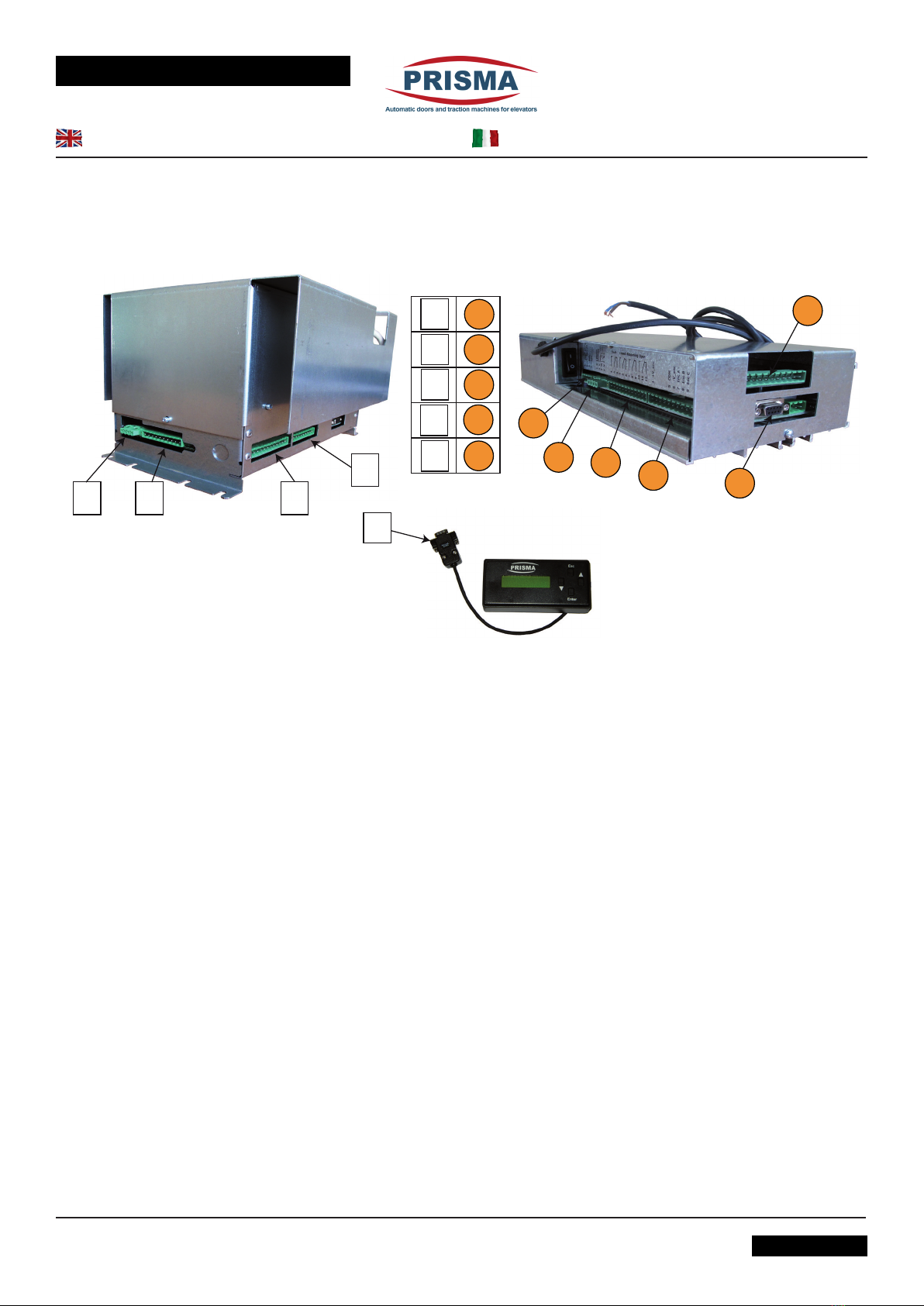
Green LED Power On
Yellow LED Safety reopening system
Red LED Fault (malfunctioning)
X1 Motor power phase
connector
X2 Encoder connector
X3 Lift control panel fedback
connector
X4 Connector for commands from
the lift control panel
X5 Battery and 24 V - 2 A output
connector
X6 User interface connector
X7 Not in use
Descriptionandeldofapplication
A TERMINE DI LEGGE E’ VIETATA LA RIPRODUZIONE O COMUNICAZIONE A TERZI SENZA NOSTRA APPROVAZIONE
ALLEGATO “A”
SOGGETTO A MODIFICHE SENZA PREAVVISO
31_42_01_01REV03
4-SPECIFICHE TECNICHE
DATI TECNICI
Alimentazione principale 230 V
Protezione lato rete Fusibile Di Tipo "F" 2 A,
accessibile dall'esterno
Potenza massima
assorbita 300 W
Alimentazione di emer-
genza 24 Vdc
Reazione posizione e
velocità Encoder 160 impulsi/giro
Fusibile alimentazione
principale F 2 A
Fusibile per uscita
alimentazione 24V 3,15 A
Attacco al motore 7 A (Tipo B) o 11 A (Tipo A)
Grado di protezione IP20
Temperatura magazzino
max. -40°C + 80°C
Temperature limite di
esercizio -5°C +45°C
Peso 2,650 Kg
LED Verde Power On
LED Giallo Intervallo costola mobile
LED Rosso Fault (malfunzionamento)
X1 Connettore di potenza fasi
motore
X2 Connettore encoder
X3 Connettore informazioni al
quadro dell'ascensore
X4 Connettore comandi dal
quadro dell'ascensore
X5 Connettore batteria e uscita
24 V - 2A
X6 Connettore interfaccia utente
X7 Non utilizzato
Descrizione e campo di applicazione

DRIVE “JAGUAR REPLACEMENT KIT”
C / 3
WITHOUT OUR CONSENT THE REPRODUCTION OR COMMUNICATION TO THIRD PARTIES IS PROHIBITED BY LAW
ANNEXE “A”
SUBJECT TO CHANGE WITHOUT NOTICE
Descriptionandeldofapplication
TYPE A AND B IDENTIFICATION LABEL
MOTOR ELECTRONIC DATA
MOTORS TYPE "B" TYPE "A"
Nominal torque
(Nm) 1 2
Peak torque
(Nm) 2,5 5
Nominal current
(A) 4,6 9
Peak current (A) 13 (limited to 7) 26 (limited to 11)
Tension lasting 24 Hours, 100% intermittence motor
HOW TO CHOOSE “JAGUAR” DRIVER ACCORDING
TO DOOR TYPE
A TERMINE DI LEGGE E’ VIETATA LA RIPRODUZIONE O COMUNICAZIONE A TERZI SENZA NOSTRA APPROVAZIONE
ALLEGATO “A”
SOGGETTO A MODIFICHE SENZA PREAVVISO
31_42_01_01REV03
Descrizione e campo di applicazione
ETICHETTA D'IDENTIFICAZIONE TIPO A E TIPO B
DATI ELETTRONICI DEL MOTORE
MOTORI TIPO "B" TIPO "A"
Coppia nominale
(Nm) 1 2
Coppia di picco
(Nm) 2,5 5
Corrente
nominale (A) 4,6 9
Corrente di picco
(A) 13 (limitati a 7) 26 (limitati a 11)
Durata tensione 24h motore ad intermittenza 100%
SCELTA DEL DRIVE “JAGUAR” PER TIPO PORTA
Door type max. C.O. Max. panel weight
Kg (landing and car) Motor
type "Jaguar"
drive Motor performances Tipo porta max.
largh. x altezza
C2C 1300x2500 120 B B 7 A C2C 1300x2500
Over Over AA 11 A Oltre
C4C 4000x2500 - A A 11 A C4C 4000x2500
C6C 4000X2500 - A A 11 A C6C 4000X2500
C2S 1300x2500 120 B B 7 A C2S 1300x2500
Over Over A A 11 A Oltre
C3S 1300x2500 120 B B 7 A C3S 1300x2500
Over Over A A 11 A Oltre
Glass panel upon
request Upon request A A 11 A Ante in vetro su
richiesta
Peso ante max. Kg
(piano e cabina) Tipo
motore "Jaguar"
drive Prestazioni Motore
DRIVE “JAGUAR REPLACEMENT KIT”
D / 1
WITHOUT OUR CONSENT THE REPRODUCTION OR COMMUNICATION TO THIRD PARTIES IS PROHIBITED BY LAW
ANNEXE “A”
SUBJECT TO CHANGE WITHOUT NOTICE
Connection
1-
START UP
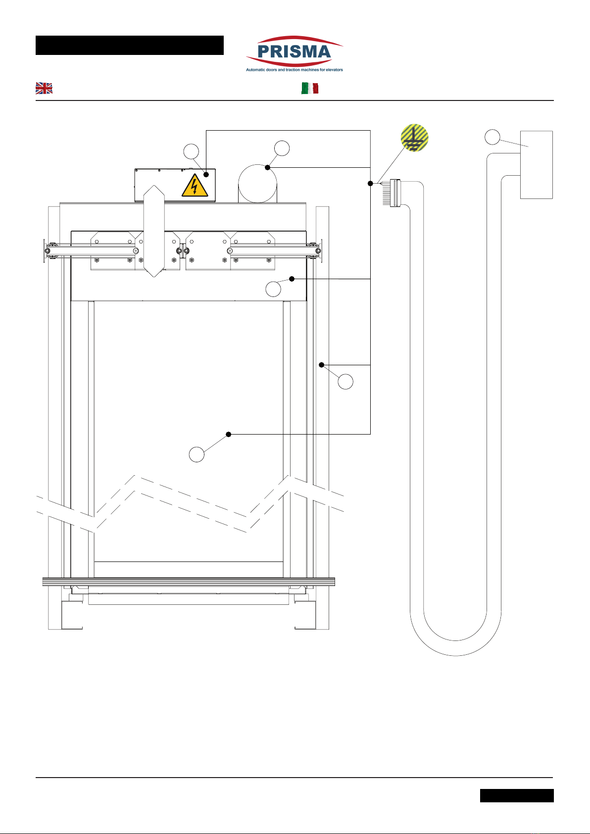
Before supplying power to the drive, ground the following
elements through the main-grounding of the lift control
panel (6):
1) Drive
2) Motor
3) Operator
4) Car
5) Sling
*ground both the yellow/green power supply cable as well
asthebrassnutalreadyxedonthedrivecasing.
M
12
3
4
6
5
A TERMINE DI LEGGE E’ VIETATA LA RIPRODUZIONE O COMUNICAZIONE A TERZI SENZA NOSTRA APPROVAZIONE
ALLEGATO “A”
SOGGETTO A MODIFICHE SENZA PREAVVISO
31_42_01_01REV03
Collegamento
1-MESSA IN SERVIZIO
Prima di alimentare il drive collegare a terra i seguenti
elementi mediante la massa principale del’impianto (6):
1) Drive*
2) Motore
3) Operatore
4) Cabina
5) Arcata
*collegare a massa sia il lo giallo/verde del cavo di
alimentazionesiailbullonediottonessatoalconteni-
tore.

DRIVE “JAGUAR REPLACEMENT KIT”
D / 2
WITHOUT OUR CONSENT THE REPRODUCTION OR COMMUNICATION TO THIRD PARTIES IS PROHIBITED BY LAW
ANNEXE “A”
SUBJECT TO CHANGE WITHOUT NOTICE
Connection
• If they are not connected yet, connect the motor power
supply connector X1 and the X2 connector of the
encoder after having grounded the system as shown
in the prior image.
• Connect the 230 V mains power and turn the switch (1)
as indicated in the following picture.
• Verify that the RIGHT - LEFT or CENTRE CLOSING set-
ting of the door is correct:
- Setup of the closing direction is performed in the factory
prior to delivery, for this reason this paragraph is only informa-
tional.
The following pictures show the wiring of the drive.
The connection between the motor and the terminal board of the
drive is performed in the factory according to the closing side of
the door, as shown in detail.
If the wiring is faulty (wrong closing direction) the drive will not
be able to distinguish opening and closing direction of the door
correctly.
-The drive must receive all commands from "clean" contacts
i.e. without potential.
X6
X7
X4
12345678910
COMMON
NOT IN USE
USER INTERFACE
PHOTOCELL N.O. PHOTOCELL N.C.
OPEN CLOSE NUDGE PHOTOCELL COMMON OPEN CLOSE PHOTOCELL
BRIDGE
A TERMINE DI LEGGE E’ VIETATA LA RIPRODUZIONE O COMUNICAZIONE A TERZI SENZA NOSTRA APPROVAZIONE
ALLEGATO “A”
SOGGETTO A MODIFICHE SENZA PREAVVISO
31_42_01_01REV03
Collegamento
• Collegare al drive, se non già collegati, il connettore
X1 di alimentazione del motore e il connettore X2
dell’encoder dopo aver collegato l’impianto a terra come
indicatonellapecedentegura.
• Collegare l’alimentazione da rete 230 V e accendere
l’interruttore (1) indicato nella seguente immagine.
• Vericare che il settaggio porta DX-SX o CENTRALE
sia corretto:
- Il settaggio relativo al senso di chiusura è eseguito in fab-
brica prima della consegna, pertanto questo paragrafo ha solo
valore informativo per i drives forniti come ricambi.
Le immagini seguenti illustrano lo schema di cablaggio del drive.
Il collegamento tra il motore e la morsettiera e tra l’encoder e la
stessa morsettiera è eseguito in fabbrica e tiene conto del senso
di chiusura della porta, come indicato nel dettaglio.
L’eventuale inversione del cablaggio relativo al senso di chiusura
della porta fa sì che il drive non distingua il senso di apertura da
quello di chiusura.
- I comandi al drive vanno impartiti mediante contatti “puliti”,
cioè liberi da potenziale.
Right/centre Closing door
Porte con chiusura verso destra/centrale Left Closing door
Porte con chiusura verso sinistra
C1S/R C1S/L
C2S/R C2S/L
C3S/R C3S/L
C2C
C4C
See following picture for connections
Vedere le connessioni nell'immagine seguente

DRIVE “JAGUAR REPLACEMENT KIT”
D / 3
WITHOUT OUR CONSENT THE REPRODUCTION OR COMMUNICATION TO THIRD PARTIES IS PROHIBITED BY LAW
ANNEXE “A”
SUBJECT TO CHANGE WITHOUT NOTICE
Connection
24V DC
12V 12V
+
-
+
-
+
-
1
2
3
4
1
2
3
v
w
n
4
u
X2
X3
X1
X5
G/Y
Pink
Brown
Yellow
Grey
Green
ENCODER
C2S/R - C2C C2S/L - C4C
C6C
+V
-V
SHIELD
A
B
C
MOTOR
(1)
9
1
2
3
4
5
6
7
8
10
9
1
2
3
4
5
6
7
8
12
10
11
NO
FAULT
DOOR CLOSED
OPEN DOOR
SAFETY
REOPENING
SYSTEM
NC
C
NO
NC
C
NO
NC
C
NO
NC
C
w
v
n
u
G/Y
Pink
Brown
Yellow
Grey
Green
ENCODER
+V
-V
SHIELD
A
C
B
MOTOR
NO
FAULT
DOOR CLOSED
OPEN DOOR
SAFETY
REOPENING
SYSTEM
NC
C
NO
NC
C
NO
NC
C
NO
NC
C
A TERMINE DI LEGGE E’ VIETATA LA RIPRODUZIONE O COMUNICAZIONE A TERZI SENZA NOSTRA APPROVAZIONE
ALLEGATO “A”
SOGGETTO A MODIFICHE SENZA PREAVVISO
31_42_01_01REV03
Collegamento
DRIVE “JAGUAR REPLACEMENT KIT”
D / 4
WITHOUT OUR CONSENT THE REPRODUCTION OR COMMUNICATION TO THIRD PARTIES IS PROHIBITED BY LAW
ANNEXE “A”
SUBJECT TO CHANGE WITHOUT NOTICE
2-
INSULATION TEST
For security reasons on the base of the regulations in force the
low tension subordinate circuit of the JAGUAR Is connected to
earth (box) by a low impedence device
Due to this, there is no insulation test to effectuate
between secondary section at low voltage of the JAGUAR
and earth.
Furthermore, the use of unsuitable imstruments may damage the
protection unit inside the device.
As the battery for emergency reopening is connected to
the secondary circuit of the JAGAUR, the battery has to
be disconnected before carrying out the insulation test
of the system.
During the text the power supply phase conductors must be
interconnected to each other.
3-
DETECTION OF POINT “0” AND
SELF LEARNING
- During this phase, make certain that the travel
of the door is not interrupted by any obstacles and that
the detected point 0 actually corresponds to fully closed
doors. In case of operator with retractable cam, the
door can be deemed as completely closed, when the
retractablecamisclosed.Incaseofoperatorswithxed
sword, the door can only be deemed as closed, when
the truck is fully leaning against the end of run rubber
installed on the upper track.
When the door is rst powered, it starts to close slowly until it
reaches the mechanical stops, thus causing the current to rise.
This position will be recognized as Point 0.
The Self-learning function must be set-up by the installer at start-
up and is required in order to have the drive memorize the number
of encoder impulses corresponding to the door clear opening.
To start the self-learning, connect the user interface (to the drive
using the X6 connector (See picture on page F1).
When the name PRISMA appears on the display, press ENTER,
use ▼and ▲ to access the Commands menu, press ENTER
again, select LEARNING with ▼and ▲ and conrm pressing
the ENTER button.
The drive performs the self-learning storing the door clear opening
data in its permanent memory, and the door remains open, waiting
for command.
Self-learning must always be performed with completely closed
doors. During this phase, make sure that the run of the doors is
not interrupted by obstacles. Otherwise, repeat the operation.
- The self-learning command is automatically performed by
the drive when turned on if it detects the presence of a brand-
new or damaged EEPROM.
Connection
A TERMINE DI LEGGE E’ VIETATA LA RIPRODUZIONE O COMUNICAZIONE A TERZI SENZA NOSTRA APPROVAZIONE
ALLEGATO “A”
SOGGETTO A MODIFICHE SENZA PREAVVISO
31_42_01_01REV03
2-TEST D’ISOLAMENTO
Per motivi di sicurezza in base alle vigenti normative le sezione
secondaria a bassa tensione del JAGUAR è collegata alla terra
(chassis) tramite un componente a bassa impedenza.
Non bisogna pertanto effettuare prove d'isolamento fra
la sezione secondaria a bassa tensione del JAGUAR e la
terra.
Peraltro, l'uso di strumentazione inadeguata potrebbe danneggiare
il dispositivo di sicurezza interno all'apparecchiatura.
Siccome la batteria di riapertura in emergenza viene
collegata sulla sezione secondaria del JAGUAR, bisogna
scollegare la batteria prima di effettuare le prove di
isolamento del sistema.
Durante la prova i conduttori di fase dell'alimentazione devono
essere tra loro interconnessi.
3-RICONOSCIMENTO DEL PUNTO “O” E
AUTOAPPRENDIMENTO
- Durante questa fase accertarsi che la corsa
delle ante non sia interrotta da ostacoli e che il punto
0 acquisito corrisponda effettivamente alla porta
completamente chiusa. In caso di operatore con camma di
accoppiamento mobile, la porta è completamente chiusa
quando la camma di accoppiamento retrattile è chiusa. In
casodioperatoreconcammadiaccoppiamentossa,la
porta si intende chiusa quando il carrello appoggia contro
il gommino di arresto meccanismo montato sulla guida.
Al momento dell’alimentazione la porta comincia a chiudersi
lentamente, fino ad arrivare contro gli arresti meccanici,
provocando l’innalzamento della corrente. Tale posizione sarà
riconosciuta come Punto 0.
La funzione di autoapprendimento deve essere comandata
dall’installatore all’atto della messa in servizio del drive, questa
operazione è necessaria al ne di far acquisire al drive il n° di
impulsi Encoder rappresentato dalla luce porta.
Per comandare l’autoapprendimento collegare l’interfaccia utente
al drive attraverso il connettore X6 (Vedi immagine pag. F1).
All’apparire della scritta PRISMA, premere il tasto ENTER,
tramite i tasti ▼e ▲portarsi sulla funzione Comandi, premere
nuovamente ENTER e, con i tasti ▼e ▲selezionare la voce AUTO
APP. e confermare premendo il tasto ENTER.
Il drive eseguirà la funzione di autoapprendimento memorizzando
nella propria memoria permanente la luce passaggio della porta;
la porta resta aperta in attesa di comandi.
L’autoapprendimento deve essere eseguito con porta
completamente chiusa. Durante questa fase accertarsi che la
corsa delle ante non sia interrotta da ostacoli. In caso contrario
ripetere l’operazione.
- Il comando di autoapprendimento è eseguito
automaticamente dal drive all’accensione nel caso in cui riscontri
la presenza di EEPROM vergine o danneggiata.
Collegamento
DRIVE “JAGUAR REPLACEMENT KIT”
D / 5
WITHOUT OUR CONSENT THE REPRODUCTION OR COMMUNICATION TO THIRD PARTIES IS PROHIBITED BY LAW
ANNEXE “A”
SUBJECT TO CHANGE WITHOUT NOTICE
Connection
4-
DRIVE JAGUAR REPLACEMENT
WIRING
If the Drive Jaguar Replacement Kit is replacing an older Jaguar
drive mode, please refer to this section and to the drawing on
page D2 for the wiring.
A B CDX1 X3 X2
X4
X1
BX2
X3
X4
A
C
D
E
E
X5
X6
X6
The Jaguar Replacement Kit (JRK) is equipped with a battery
charger.
If Jaguar drive to be replaced is tted with a 2-battery and charger
system, disconnect the batteries from the charger.
Connect the two batteries to the X5 connector of the JRK drive,
according to the chart on page two of the present manual.
A TERMINE DI LEGGE E’ VIETATA LA RIPRODUZIONE O COMUNICAZIONE A TERZI SENZA NOSTRA APPROVAZIONE
ALLEGATO “A”
SOGGETTO A MODIFICHE SENZA PREAVVISO
31_42_01_01REV03
Collegamento
4-CABLAGGIO SOSTITUZIONE DRIVE
JAGUAR
Se il Drive Jaguar Replacement Kit è stato acquistato per sostiuire
un Drive Jaguar preinstallato, si prega di riferirsi alla presente
sezione ed allo schema di pagina D2 per il cablaggio.
Il drive Jaguar Replacement Kit (JRK) ha il caricabatterie
incorporato.
Se il drive Jaguar da sostituire è dotato di un sistema contenente
le due batterie ed il caricabatteria, disconnettere il caricabatterie
dalle batterie.
Collegare, quindi, le due batterie al connettore X5 del drive JRK
secondo lo schema di pagina 2 del presente manuale.

DRIVE “JAGUAR REPLACEMENT KIT”
E / 1
WITHOUT OUR CONSENT THE REPRODUCTION OR COMMUNICATION TO THIRD PARTIES IS PROHIBITED BY LAW
ANNEXE “A”
SUBJECT TO CHANGE WITHOUT NOTICE
Control Board Commands
1-
OPENING
Opening of the door must be controlled by the elevator control
board by closing terminals (10-9) in X4 or by launching the
command from the user interface.
The opening command from the elevator control board must stay
on during the entire opening phase; if not, the door will stop and
wait for new commands. In this state, it is possible to operate the
door manually, because there is no motor torque.
The opening command is ignored in the following instances:
- Searching of Point 0
- Self-learning phase
- When the door closing command is active.
For the door opening command to be accepted during the closing
phase it is necessary to interrupt the door close command rst.
The opening command is void if the following commands are
active:
- Alarm on
- Door closing with Nudge
- Door closing command from the user interface.
2-
CLOSING
Closing of the door must be controlled by the elevator control
board by closing terminals (10-8) in X4 or by launching the
command from the user interface.
The closing command from the elevator control board must stay
on during the entire closing phase; if not, the door will stop and
wait for new commands. In this state, it is possible to operate
the door manually.
The closing command is ignored in the following instances:
- Searching of Point 0
- Self-learning phase
- When the door opening command is active.
For the door closing command to be accepted during the opening
phase it is necessary to interrupt the door open command.
The closing command is void if the following commands are
active:
- Alarm On;
- Door closing with Nudge;
- Door opening command from the user interface;
- Safety reopening system is activated;
- Reopening command from the photocell.
3-
NUDGING
In this mode, the drive performs a forced closing of the door
with a safety torque corresponding to the parameter of the
safety reopening system, in compliance with EN 81.1/2 and at
very low speed.
Nudging is optional and, if needed, must be controlled from
the control board of the elevator, after a certain number of
unsuccessful tries to close the doors.
A sound alarm to warn passengers in the cabin that the doors
are going to be forcefully closed should be setup whenever the
A TERMINE DI LEGGE E’ VIETATA LA RIPRODUZIONE O COMUNICAZIONE A TERZI SENZA NOSTRA APPROVAZIONE
ALLEGATO “A”
SOGGETTO A MODIFICHE SENZA PREAVVISO
31_42_01_01REV03
Comandi del quadro di manovra
1-APRE
L’apertura porta deve essere comandata dal quadro di manovra
dell’ascensore tramite la chiusura dei morsetti (10-9) in X4, oppure
tramite apposito comando da interfaccia utente.
Il comando di apertura proveniente dal quadro di manovra
dell’ascensore dovrà permanere per tutta la fase di apertura, in
caso contrario la porta si arresta in attesa di nuovi comandi. In
questo stato è possibile agire manualmente sulla porta, poiché il
motore non resta in coppia.
Il comando di apertura è ignorato nei seguenti casi:
- in fase di ricerca del Punto 0;
- in fase di autoapprendimento;
- in presenza del comando di chiusura.
Per comandare l’apertura della porta durante la fase di chiusura è
quindi necessario prima interrompere il comando di chiusura.
Il comando di apertura è nullo in presenza dei seguenti coman-
di:
- stato di allarme;
- chiusura tramite Nudge;
- comando di chiusura.
2-CHIUDE
La chiusura porta deve essere comandata dal quadro di manovra
dell’ascensore tramite la chiusura dei morsetti (10-8) in X4, oppure
tramite apposito comando da interfaccia utente.
Il comando di chiusura dal quadro di manovra dell’ascensore
dovrà permanere per tutta la fase di chiusura, in caso contrario
la porta si arresta in attesa di nuovi comandi.
In questo stato è possibile agire manualmente sulla porta, poiché
il motore non resta in coppia.
Il comando di chiusura è ignorato nei seguenti casi:
- in fase di ricerca del Punto 0;
- in fase di autoapprendimento;
- in presenza del comando di apertura.
Per comandare la chiusura della porta durante la fase di apertura
è quindi necessario prima interrompere il comando di apertura.
Il comando di chiusura è nullo in presenza dei seguenti
comandi:
- stato di allarme;
- chiusura tramite Nudge;
- comando di apertura proveniente dall’interfaccia utente;
- intervento della costola mobile;
- comando di riapertura proveniente dalla fotocellula.
3-NUDGE
In questa modalità il drive esegue una chiusura forzata della porta
con la coppia del motore massima corrispondente al parametro
della costola mobile, che rispetta la normativa EN 81.1/2 e a
velocità molto bassa.
La funzione Nudge è facoltativa e, se richiesta, deve essere
comandata dal quadro di manovra dell’ascensore dopo n-volte che
l’operatore ha tentato di richiudere, senza riuscirvi, le ante.
Normalmente, assieme alla funzione nudge, deve essere attivato
un segnale sonoro che avvisa i passeggeri in cabina della chiusura

DRIVE “JAGUAR REPLACEMENT KIT”
E / 2
WITHOUT OUR CONSENT THE REPRODUCTION OR COMMUNICATION TO THIRD PARTIES IS PROHIBITED BY LAW
ANNEXE “A”
SUBJECT TO CHANGE WITHOUT NOTICE
Control Board Commands
nudging function is used.
The function is controlled by closing terminals (10-7) in X4 and
only remains active while the command stays on. Nudge may be
commanded during the open stationary state and while the door
is in movement as well.
If the command is interrupted prior to complete closing of the
door, the drive performs the opening or closing command coming
from the elevator control board. Should this command not be
present, the door will remain still, waiting for command.
4-
PHOTOCELL
This function is only enabled during the closing phase.
Closing of terminals (10-5) in X4 causes the door to reopen
according to the speed pro le set for the estimated position.
The drive will not accept any door closing commands.
For photocell with N.C. manually bridge the 5-6 in X4 terminals and
apply signal from the photocell between the 10 and 4 terminals
in X4 (see detailed sheet at pag D3)
5-
SAFETY REOPENING SYSTEM
This function is only enabled during the closing phase.
The presence of an obstacle between the closing doors will cause
a rise in the current.
Exceeding the level of the set torque limit causes the doors
to reopen following the speed prole set for the estimated
position.
A TERMINE DI LEGGE E’ VIETATA LA RIPRODUZIONE O COMUNICAZIONE A TERZI SENZA NOSTRA APPROVAZIONE
ALLEGATO “A”
SOGGETTO A MODIFICHE SENZA PREAVVISO
31_42_01_01REV03
Comandi del quadro di manovra
forzata della porta.
La funzione viene comandata tramite la chiusura del morsetto
(10-7) in X4 e rimane attiva solo no a che permane tale comando.
Il Nudge può essere comandato durante lo stato di stazionamento
di apertura e anche durante il movimento della porta.
Se il comando viene a mancare prima della completa chiusura,
il drive esegue i comandi di apertura o chiusura provenienti dal
quadro di manovra dell’ascensore.
In assenza di tali comandi la porta resta ferma in attesa.
4-FOTOCELLULA
Questa funzione è abilitata soltanto durante la fase di chiusura.
La chiusura del morsetto (10-5) in X4 determina la riapertura della
porta seguendo il prolo delle velocità preimpostate.
In questa fase il drive non accetta comandi di chiusura porta.
In caso di fotocellula con contatto N.C. collegare manualmente
i morsetti 5-6 di X4 e applicare il segnale della fotocellula fra i
morsetti 10 e 4 di X4 (Vedi schema dettagliato a pag. D3).
5-COSTOLA MOBILE
Questa funzione è attiva soltanto durante la fase di chiusura.
L’interposizione di un ostacolo tra le ante che chiudono provoca
l’innalzamento della corrente.
Il superamento della soglia di corrente programmata provoca
quindi la riapertura della porta seguendo il prolo di velocità
relativo alla posizione stimata.

DRIVE “JAGUAR REPLACEMENT KIT”
F / 1
WITHOUT OUR CONSENT THE REPRODUCTION OR COMMUNICATION TO THIRD PARTIES IS PROHIBITED BY LAW
ANNEXE “A”
SUBJECT TO CHANGE WITHOUT NOTICE
Drive Parametrization
1-
USER INTERFACE
The programming pad (user interface) is made up of a keyboard
with 4 buttons (▼, ▲, Enter, Esc) and an alphanumerical display
(with 16 characters on two lines) and communicates with the drive
via a RS232 serial connection (Connector X6).
X6
Using the ▼and ▲buttons it is possible to select the commands
to give to the drive and con rm them by pressing the ENTER
button.
When the user interface is connected to the X6 terminal, it recalls
the current drive parameters in use and makes them visible to
the user for checking or changes.
When turned on, PRISMA will appear on the alphanumerical
display on the keyboard. By pressing ENTER the interface menu
is activated.
The interface is structured with 5 main menu levels: Language,
Commands,OpeningProle,ClosingProle,Auxiliaries.
All of the parameter changing operations may be performed with
the door in movement. They must be saved using the SAVE
command and will be applied only at the following actioning.
2-
LANGUAGE
Using the ▼and ▲ buttons it is possible to choose the desired
language and conrm it using ENTER, thus immediately switching
to the newly selected language; this selection can be saved using
the Save command in the command menu.
3-
COMMANDS
• The commands Open and Close have priority over the
elevator control board commands and open and close the
door immediately.
• The Save command causes all of the datas handled by the
interface to be saved in the permanent memory of the drive.
• In any case the modied datas are permanently saved after
every applied change.
• The Default command replaces all the current data in use with
the original factory settings, except for the security torque,
which remains the last saved one.
A TERMINE DI LEGGE E’ VIETATA LA RIPRODUZIONE O COMUNICAZIONE A TERZI SENZA NOSTRA APPROVAZIONE
ALLEGATO “A”
SOGGETTO A MODIFICHE SENZA PREAVVISO
31_42_01_01REV03
Parametrizzazione del Drive
1-INTERFACCIA UTENTE
L’interfaccia utente (pad di programmazione) consiste in
una tastiera con 4 pulsanti (▼, ▲, Enter, Esc) ed un display
alfanumerico (a 16 caratteri su due linee ) e comunica con il drive
tramite una connessione seriale RS232 (Connettore X6).
Tramite i tasti ▼e ▲ è possibile selezionare i comandi da impartire
al drive e confermarli con la pressione del tasto ENTER.
All’atto della connessione con X6 l’interfaccia interroga il drive sui
parametri memorizzati e li rende disponibili all’utente per essere
controllati o modicati.
Al momento dell’accensione, sul display alfanumerico dell’interfaccia
utente appare la scritta PRISMA, premendo ENTER si attiva il
menu dell’interfaccia.
L’interfaccia è strutturata su 5 menù principali: Lingua, Comandi,
Profilo Apertura e Profilo Chiusura, Ausiliari.
Tutte le operazioni di modica dei parametri possono essere
effettuate con porta in movimento. La loro memorizzazione
avviene attraverso il comando SAVE ed è applicata al ciclo
successivo.
2-LINGUA
Tramite i tasti ▼e ▲ è possibile scegliere la lingua desiderata,
la conferma tramite ENTER determina il passaggio immediato alla
lingua selezionata, tale scelta potrà poi essere salvata tramite il
comando Salva nel menu comandi.
3-COMANDI
• I comandi Apri e Chiudi hanno priorità rispetto ai comandi del
quadro di manovra dell’ascensore e fanno aprire o chiudere la
porta immediatamente.
• Il comando Salva fa sì che tutti i dati gestiti dall’interfaccia
siano salvati sulla memoria permanente del drive.
• In ogni caso i dati vengono salvati in modo permamenente
dopo ogni modica.
• Il comando Default sostituisce tutti i dati memorizzati con
quelli originali di fabbrica tranne la corrente di sicurezza che
resterà quella ultima memorizzata.

DRIVE “JAGUAR REPLACEMENT KIT”
F / 2
WITHOUT OUR CONSENT THE REPRODUCTION OR COMMUNICATION TO THIRD PARTIES IS PROHIBITED BY LAW
ANNEXE “A”
SUBJECT TO CHANGE WITHOUT NOTICE
Drive Parametrization
The default values (set by producer of the drive) do not always
correspond to the closing or opening best pro le for all door
types. Please refer to the values indicated on the label attached
to the drive itself.
4-
OPENING AND CLOSING PROFILES
Parameters for managing of the OPEN settings
Parameters for managing of the CLOSE settings
OPEN
CLOSE
A TERMINE DI LEGGE E’ VIETATA LA RIPRODUZIONE O COMUNICAZIONE A TERZI SENZA NOSTRA APPROVAZIONE
ALLEGATO “A”
SOGGETTO A MODIFICHE SENZA PREAVVISO
31_42_01_01REV03
Parametrizzazione del Drive
I valori di default (impostati dal produttore del drive) non sempre
corrispondono al prolo ottimale di chiusura e apertura di tutti i
modelli di porte, riferirsi pertanto ai valori riportati sull’etichetta
del drive stesso.
4-PROFILI DI APERTURA E CHIUSURA
Parametri per la gestione delle variabili di APERTURA
Parametri per la gestione delle variabili di CHIUSURA
APERTURA
CHIUSURA
DRIVE “JAGUAR REPLACEMENT KIT”
F / 3
WITHOUT OUR CONSENT THE REPRODUCTION OR COMMUNICATION TO THIRD PARTIES IS PROHIBITED BY LAW
ANNEXE “A”
SUBJECT TO CHANGE WITHOUT NOTICE
Drive Parametrization
PARAMETERS VALUES DESCRIPTION
Position A-Ap
SEE THE LABEL ON THE DRIVE
Start opening
acceleration ramp
Position B-Ap End opening
acceleration ramp
Position C-Ap Start opening
deceleration ramp
Position D-Ap End opening
deceleration ramp
Position Z-Ch Start coupling cam
closing ramp
Position A-Ch End closing
deceleration ramp
Position B-Ch Start closing
deceleration ramp
Position C-Ch End closing
acceleration ramp
Position D-Ch Start closing
acceleration ramp
Speed vA-Ap Coipling cam opening
speed
Speed vH-Ap Maximum opening
speed
Speed vZ-Ap End opening speed
Speed vA-Ch End closing speed
Speed vH-Ch Maximum closing
speed
Speed vZ-Ch Starting closing speed
Limit torque
Note: The parameter
Z-Ch, in the case of
an operator without
mobile coupling cam,
may be reduced to 0.
Open stationary torque
(Wait Torq. Op)
Closed stationary torque
(Wait Torq. Cl)
Maximum torque
Security torque
- Parameter D-Ch must always be lower or equal
to 99.
The parameters relevant to the current are expressed in
hundredths of the maximum current of the system.
The set parameters are expressed in values of percentage
of clear opening of the door (for example with a door width
of 900 mm, the parameter 60 = 540 mm from the beginning of
the run).
A TERMINE DI LEGGE E’ VIETATA LA RIPRODUZIONE O COMUNICAZIONE A TERZI SENZA NOSTRA APPROVAZIONE
ALLEGATO “A”
SOGGETTO A MODIFICHE SENZA PREAVVISO
31_42_01_01REV03
Parametrizzazione del Drive
PARAMETRI VALORI DESCRIZIONE
Posizione A-Ap
VEDERE ETICHETTA APPLICATA SUL DRIVE
Inizio rampa
accelerazione apertura
Posizione B-Ap Fine rampa
accelerazione apertura
Posizione C-Ap Inizio rampa
decelerazione apertura
Posizione D-Ap Fine rampa
decelerazione apertura
Posizione Z-Ch Inizio rampa chiusura
abbinamento
Posizione A-Ch Fine rampa
decelerazione chiusura
Posizione B-Ch Inizio rampa
decelerazione chiusura
Posizione C-Ch Fine rampa
accelerazione chiusura
Posizione D-Ch Inizio rampa
accelerazione chiusura
Velocità vA-Ap Velocità apertura
abbinamento
Velocità H-Ap Velocità massima in
apertura
Velocità vZ-Ap Velocità nale in
apertura
Velocità vA-Ch Velocità nale in
chiusura
Velocità vH-Ch Velocità massima in
chiusura
Velocità vZ-Ch Velocità iniziale in
chiusura
Corrente di ne corsa
N.B. Il parametro Z-Ch,
in caso di operatore
senza camma di
accoppiamento mobile,
deve essere ridotto
a 0.
Corrente di
stazionamento Apertura
Corrente di
stazionamento Chiusura
Corrente Massima
Corrente di sicurezza
- Il parametro D-Ch deve essere sempre inferiore
o uguale a 99.
l parametri relativi alla corrente sono espressi in percentuale
della corrente massima del sistema.
I parametri impostati sono espressi in valori percentuali della
luce passaggio della porta (per esempio con porta di 900 mm
il parametro 60 = 540 mm dall’inizio della corsa).

DRIVE “JAGUAR REPLACEMENT KIT”
F / 4
WITHOUT OUR CONSENT THE REPRODUCTION OR COMMUNICATION TO THIRD PARTIES IS PROHIBITED BY LAW
ANNEXE “A”
SUBJECT TO CHANGE WITHOUT NOTICE
Parametrisation du driveDrive Parametrization
The parameters relative to the reference speeds are
expressed in percentage of the maximum speed that the
system can reach starting from Point 0.
It is possible to select the various points in the opening and
closing pro les using the ▼and ▲ buttons, On the display of
the user interface rst the positions and then the speeds are
shown. Press the ENTER button to access the function indicated
on the user interface display: the parameters saved in the drive
will start to blink on the display.
Using the ▼and ▲ buttons it is possible to change the parameter
(decreasing it or increasing it). Use the ENTER button to conrm
and temporarily store the newlyselected value.
EXAMPLE: To modify the parameter BAp from 12 to 15, go
to the function OPEN PROFILE using the ▼and ▲buttons.
Press ENTER. The value 12 will start to blink. Using the ▲but-
ton, increase the value to 15. Wait for the door to either be
open or closed and then press ENTER once again.
The new parameter is already saved, but only temporarily. In
fact, should there be a power outage, the value will be lost and
the last permanently stored parameters (EEPROM) will be
restored.
5-
AUXILIARIES
The auxiliary parameters are represented by five references of
current expressed in hundredths the maximum value.
Maximum Torque: this represents the maximum torque that
the drive can supply according to the requested speed profile.
Limit Torque: this represents the level of current that must
be exceeded in order to acquire the status of completely open
or completely closed door, so that the drive will set itself to the
relative stationary torque.
Stationary opening torque: it sets the pushing force needed
to keep the door open.
Stationary closing torque: it sets the pushing force needed
to keep the door closed.
Security Torque: the security torque is used as a limit level
for the Safety Reopening System, the Nudging and as limit dur-
ing the first detection of the Point 0.
A TERMINE DI LEGGE E’ VIETATA LA RIPRODUZIONE O COMUNICAZIONE A TERZI SENZA NOSTRA APPROVAZIONE
ALLEGATO “A”
SOGGETTO A MODIFICHE SENZA PREAVVISO
31_42_01_01REV03
I parametri relativi alle velocità di riferimento sono
espressi percentualmente rispetto alla velocità massima
raggiungibile dal sistema, partendo sempre dal punto 0.
È possibile selezionare i vari punti dei proli di apertura e chiusura
sempre attraverso i tasti ▼e ▲. Sul display dell’interfaccia utente
appariranno prima le posizioni e poi le velocità.
Premendo il pulsante ENTER si entra nella funzione indicata sul
display dell’interfaccia utente ed il parametro memorizzato nel
drive inizierà a lampeggiare sul display.
Attraverso i tasti ▼e ▲si può variare tale parametro (diminuirlo
oppure aumentarlo), tramite il tasto ENTER si conferma il nuovo
valore scelto e lo si memorizza provvisoriamente.
ESEMPIO: volendo modificare il parametro B-Ap da 12 a 15,
portarsi nella funzione PROFILO APERTURA usando i tasti ▼
e ▲. Premendo ENTER, il valore 12 inizia a lampeggiare, con il
tasto ▲aumentare il valore a 15, attendere che la porta sia
chiusa o aperta e premere nuovamente il tasto ENTER.
Il nuovo parametro è già memorizzato, ma in modo non per-
manente, infatti in caso di interruzione dell’alimentazione verrà
perso e si ricaricherà in memoria il parametro memorizzato
recedentemente in modo definitivo (EEPROM).
5-AUSILIARI
I parametri ausiliari sono rappresentati da cinque riferimenti di
corrente espressi in centesimi del valore massimo.
Coppia Massima: rappresenta la massima corrente erogabile
dal drive per poter adeguarsi al profilo di velocità richiesto.
Coppia di Fine Corsa: rappresenta la soglia di corrente che
è necessario superare per acquisire lo stato di porta comple-
tamente aperta o completamente chiusa e quindi passare alle
relative correnti di stazionamento.
Coppia di Stazionamento Aperto: permette di regolare la
spinta necessaria per mantenere la porta aperta.
Coppia di Stazionamento Chiuso: permette di regolare la
spinta necessaria per mantenere la porta chiusa.
Coppia di Sicurezza: la coppia di sicurezza è utilizzata come
soglia per comandare la Costola Mobile, la chiusura per Nudg-
ing e come limite durante la prima chiusura per il riconosci-
mento del Punto 0.

DRIVE “JAGUAR REPLACEMENT KIT”
G / 1
WITHOUT OUR CONSENT THE REPRODUCTION OR COMMUNICATION TO THIRD PARTIES IS PROHIBITED BY LAW
ANNEXE “A”
SUBJECT TO CHANGE WITHOUT NOTICE
Protection and alarm signals
1-
SHORT CIRCUIT
This type of protection is always present in each phase of
operation and cannot be deactivated.
It protects the phases of the motor from short circuits or damage
to the power stage. Whenever the protection is active the Red
Led turns on; all relays will be disconnected.
It is possible to exit from the Fault state only by cutting and
restoring power to the drive.
If the fault status remains, disconnect the motor. It the fault
status continues, it means that the drive has incurred permanent
damages and must be replaced.
2-
IxT HEAT PROTECTION OF THE MOTOR
This function is always active and protects the motor from
overloads due to mechanical hardening or obstacles hindering
the normal run of the door.
If the current absorbed by the motor is higher than the set level
depending on the motor type, for more than 7 sec., the driver
is disabled and stends by for 15 sec., it will then close the door
in low speed mode.
If closing fails and the current is higher than the threshold again,
the above described cycle will be repeated.
After a third failed attempt, the driver will enter the Fault state.
If the obstacle is removed, after one regular cycle the counter
resets itself.
- IxT protection can also set off because of bad reading
of the quotes (dirty, faulty or skidding encoder, or traction belt
jumps), so that the impulse counter perceives the door being in
an intermediate position even though the door is actually at the
end of the run already.
3-
SAFETY REOPENING SYSTEM
If a hindrance is detected during the closing phase, the door
reopens and the yellow led turns on.
If the close command persists, the door tries to close again, if
the hindrance was not removed, the cycle goes on indefinitely.
The safety reopening system is not active in the last 20 mm of
the run, so that in case of a hindrance in this part of the path,
the door will stop without reopening.
If the hindrance is removed the door completes the closing phase
and the red led turns on, even though the door is working
correctly.
The safety reopening system is not active in the rst 40 mm of
the closing phase run.
4-
EMERGENCY POWER SUPPLY
(OPTIONAL)
By connecting 4(+) e 3(-) terminals in X5 with a 24V (1,3
A/h min) battery, the drive can perform all standard operations
with reduced maximum speed.
A TERMINE DI LEGGE E’ VIETATA LA RIPRODUZIONE O COMUNICAZIONE A TERZI SENZA NOSTRA APPROVAZIONE
ALLEGATO “A”
SOGGETTO A MODIFICHE SENZA PREAVVISO
31_42_01_01REV03
Protezione e segnali d’allarme
1-CORTOCIRCUITO
Questo tipo di protezione è sempre presente in ogni fase di
funzionamento e non è disattivabile.
Protegge dal corto circuito sulle fasi del motore o dal guasto
allo stadio di potenza. L’intervento della protezione è segnalato
dall’accensione del Led Rosso, tutti i relè saranno diseccitati.
È possibile uscire dallo stato di Fault soltanto togliendo e ridando
alimentazione al drive.
Se lo stato di fault permane, scollegare il motore; se lo stato di
fault permane ancora, il drive ha subito danni permanenti e deve
essere sostituito.
2-PROTEZIONE TERMICA DEL MOTORE
IxT
La funzione è sempre attiva e protegge il motore da sovraccarichi
dovuti a indurimenti meccanici o ostacoli che impediscano la
normale corsa della porta.
Se la corrente assorbita dal motore supera la soglia impostata
corrispondente al tipo di motore, per un tempo superiore a 7 sec.,
il drive si disabilita e rimane in pausa per 15 sec. per poi eseguire
una chiusura a velocità ridotta.
Se la chiusura non riesce e la corrente supera nuovamente la
soglia, si ripete il ciclo sopra descritto.
Dopo il terzo tentativo non riuscito il drive entra nello stato di
fault, se invece l’ostacolo è rimosso, dopo un ciclo regolare il
conteggio si azzera.
- La protezione di IxT può intervenire anche per errata
lettura delle quote, (encoder sporco o difettoso, slittamento dello
stesso o salto dei denti della cinghia di trasmissione), per cui il
conteggio impulsi rileva la porta in posizione intermedia, mentre
la stessa è a ne corsa.
3-COSTOLA MOBILE
Se in chiusura è rilevato un ostacolo, la porta si riapre e si ac-
cende il led giallo.
Se permane il comando di chiusura,la porta torna a chiudersi,
se l’ostacolo non è stato rimosso, ripete il ciclo all’infinito.
Nell’ultimo tratto di 20mm, la costola mobile non è attiva, pertanto
se vi è un ostacolo, in questo tratto la porta si ferma senza
riaprirsi automaticamente.
Se l’ostacolo è rimosso, la porta finisce la chiusura e, pur
continuando a funzionare correttamente, il led rosso del drive
si accende.
La costola mobile non è attiva nella fase iniziale della chiusura,
più precisamente dalla posizione di porta aperta per una corsa
di 40mm.
4-ALIMENTAZIONE DI EMERGENZA
(OPZIONALE)
Collegando ai morsetti 4(+) e 3(-) in X5 una batteria da 24V
(1,3 A/h min) il drive può eseguire tutte le normali funzioni con
velocità massima ridotta.
Popular Door Opening System manuals by other brands


Automatic Technology
Automatic Technology DOMINATOR ShedMaster GDO-8V3 instruction manual

GEZE
GEZE TS 5000 RFS KB manual

MS Sedco
MS Sedco 608 Series installation instructions

G-Fittings
G-Fittings 45.100x.090.12 quick start guide

BFT
BFT OBERON TRI A2000 INV Installation and user manual

Helm
Helm GT-L 80 G 413 installation instructions