manuals.online logo
Brands
  1. Home
  2. •
  3. Brands
  4. •
  5. MS Sedco
  6. •
  7. Door Opening System
  8. •
  9. MS Sedco 608 Series User manual

MS Sedco 608 Series User manual

608 Series
Heavy Duty Switch Bollard INSTALLATION INSTRUCTIONS
8701 Castle Park Drive Indianapolis, Indiana 46256
Telephone: (800) 842-2545/(317) 842-2545 www.mssedco.com custsvc@mssedco.com
Page 1
(/MANU) 608v0808
SURFACE MOUNT INSTALLATION
IN GROUND INSTALLATION
FIGURE 1a
FIGURE 1b
Section 1
General Description
The 608 Series switch bollard is designed to provide a
freestanding, self-contained automatic door activation
device that can be installed at any location. While
numerous options are available from the factory, this
manual covers installation steps for our most common
versions.
Section 2
Basic Installation
SURFACE MOUNT INSTALLATION WITH INTERNAL SHOE
(see Figure 1a)
1) Drill concrete for two 3/8" x 3" anchor bolts provided
using the mounting shoe as a template.
2) Place plastic rust shield provided over holes in the
concrete, set mounting shoe onto the rust shield.
NOTE: If bollard switch is to be hardwired, pull
conduit through holes in the center of the rust
shield and mounting shoe. Pull electrical wires
long enough to be accessible from the top of the
bollard once mounted (approximately 42”).
3) Hammer anchor bolts into holes in concrete
shimming as necessary to level bollard. Securely
tighten anchor bolts.
4) Slide bollard over mounting shoe and secure with the
four 1/4"-20 x 1/2" bolts provided. Caulk around
base of bollard as needed.
PROCEED TO SECTION 3-WIRING
SURFACE MOUNT INSTALLATION WITH EXTERNAL SHOE
(see Figure 1b)
1) Drill concrete for four 5/16” x 2 1/2” power bolts
provided using the mounting shoe as a template.
2) Place plastic rust shield provided over holes in the
concrete, set bollard onto the rust shield.
NOTE: If bollard switch is to be hardwired, pull
conduit through holes in the center of the rust
shield and mounting shoe. Pull electrical wires
to top of bollard so they are accessible.
3) Hammer power bolts into holes in concrete
shimming as necessary to level bollard. Securely
tighten power bolts.
4) Caulk around base of bollard as needed.
PROCEED TO SECTION 3-WIRING
IN-GROUND MOUNT INSTALLATION (see Figure 1c)
1) Core a 3” diameter hole in the concrete 12” deep. If
no concrete exists, dig a hole 12” deep.
2) Secure the in-ground mounting shoe to the bollard
with the four 1/4-20 x 1/2" bolts provided.
3) Place the entire bollard assembly into prepared hole.
NOTE: If bollard switch is to be hardwired, pull
conduit through hole in the center of the
mounting shoe. Pull electrical wires to top of
bollard so they are accessible.
4) Pour concrete into hole.
5) Push bollard further into the hole until base is at
proper height.
6) Level and brace bollard.
7) Once all concrete has cured, caulk around base of
bollard as needed.
PROCEED TO SECTION 3-WIRING
!
!
!
5"
5"
GROUND LEVEL
L
1/4-20 x 1/2” Bolt
MOUNTING
SURFACE
RUST SHIELD
3/8" x 3" ANCHOR
BOLTS & BRACKET
1/4-20 x 1/2” Bolt
MOUNTING
SURFACE
RUST SHIELD
5/16” x 2 1/2”
Power Bolts
9“ SQUARE
WELDED FOOT
FIGURE 1c
608 Series
Heavy Duty Switch Bollard INSTALLATION INSTRUCTIONS
8701 Castle Park Drive Indianapolis, Indiana 46256
Telephone: (800) 842-2545/(317) 842-2545 www.mssedco.com custsvc@mssedco.com
Page 2
(/MANU) 608v0808
PLASTIC CAP
TRANSMITTER AND
SPACER PLATFORM
PRESS
9V
PCB
300MHz
390MHz
HDRC™
FREQUENCY SELECTION
SWITCH
1 2 3 4 5 6 7 8 9 10 11 12
O
N
12 POSITION SECURITY
CODE SWITCH
ClearPath ™
HDRC™ Program 1-12
300 MHz Program 1-10
390 MHz Program 1-12
BATTERY HARNESS
Section 3
Wiring
HARDWIRED
1) Connect the two signal wires to the appropriate contacts on the switch. (Standard connections are COM and N.O.)
2) Set the spacer platform (provided) in the top of the switch bollard opposite to the cap mounting holes.
3) Install the cap and fasten with the two 8-32 x 1/2" screws provided.
NOTE: Two signal wires are required per switch on vestibule models.
RADIO CONTROL (WIRELESS)
When a ClearPath radio transmitter option is ordered from the factory, the 608 series bollard will come complete with
the transmitter and battery mounted on its platform ready to be installed under the plastic cap. The CP/TX-P, CP/STX-P
(vestibule sequencing version), and CP/TX-VP (2 transmitters) feature 3 selectable frequencies in a single device: High
Definition Radio Control™ (HDRC™), 300 MHz and 390 MHz.
1) SELECT FREQUENCY: Select the desired frequency, via the 3-position slide switch on the transmitter circuit board
(Fig. 1). HDRC™ is factory setting.
FIGURE 1
2) SELECT SECURITY CODE: Program the desired security code, via the 12 dip
switches on the transmitter circuit board (Fig. 1).
NOTE: For sequencing transmitters refer to CP/STX-P installation
instructions for proper programming.
3) Plug the 2-lead transmitter wiring harness onto the "COM" (Common)
and "N.O." (Normally Open) contacts located on the door activator's
microswitch.
4) Set transmitter platform in the top of bollard opposite to the cap screw holes.
5) Install the cap and secure it with the two 8-32 screws provided.
NOTE: Vestibule switch bollards are supplied with two transmitters
(one per switch).
NOTICE: This device complies with Part 15 of the FCC
rules. Operation of this device is subject to the
following two conditions: 1) This device may not
cause harmful interference and 2) This device
must accept any interference received, including
interference that may cause undesired operation.
Any changes or modifications not expressly
approved by MS SEDCO could void the user’s
authority to operate this equipment.
!
!
!
!
HDRC™: MS SEDCO proprietary technology
300 MHz: Compatible with Multicode™ products
390 MHz: Compatible with MS SEDCO and GENIE™ products
MICROSWITCH ASSEMBLY
ClearPath ™
MICRO-SWITCH
UL LISTED
SPDT, Momentary
RATED: 15A@ 125V AC
COM
N.C.
N.O.
Rubber Bellows
Insert rubber bellows
over spring on
exterior switches for
weather tight fit!

Other MS Sedco Door Opening System manuals

MS Sedco ID20 User manual

MS Sedco

MS Sedco ID20 User manual

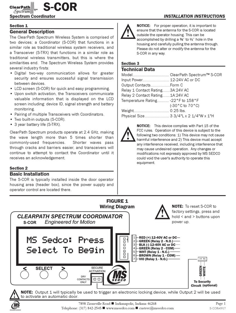
MS Sedco CleraPath Spectrum S-COR User manual

MS Sedco

MS Sedco CleraPath Spectrum S-COR User manual

Popular Door Opening System manuals by other brands

Johnson Controls PGP303 installation guide

Johnson Controls

Johnson Controls PGP303 installation guide

Visionis VIS-440 Series installation manual

Visionis

Visionis VIS-440 Series installation manual

Automatic Technology Axess Pro Series 3000 installation instructions

Automatic Technology

Automatic Technology Axess Pro Series 3000 installation instructions

Lamp FD50-H installation manual

Lamp

Lamp FD50-H installation manual

Kesseböhmer Hettich Actro Mounting instructions

Kesseböhmer

Kesseböhmer Hettich Actro Mounting instructions

Record K32 ST user manual

Record

Record K32 ST user manual

GEZE TS 4000 troubleshooting manual

GEZE

GEZE TS 4000 troubleshooting manual

Roger Technology H85/TDS Instruction and warnings for the installer

Roger Technology

Roger Technology H85/TDS Instruction and warnings for the installer

Dormakaba TS 98 XEA Mounting instructions

Dormakaba

Dormakaba TS 98 XEA Mounting instructions

Beninca ZED24 manual

Beninca

Beninca ZED24 manual

SANKI S-CON MINI SLIM Operating and service manual

SANKI

SANKI S-CON MINI SLIM Operating and service manual

DSC PG8949 installation instructions

DSC

DSC PG8949 installation instructions

Canaropa 4000CNS Series installation instructions

Canaropa

Canaropa 4000CNS Series installation instructions

Entrematic Ditec KS200VA installation manual

Entrematic

Entrematic Ditec KS200VA installation manual

Label Neptis SMP user manual

Label

Label Neptis SMP user manual

AIRTEQ 8250 Series manual

AIRTEQ

AIRTEQ 8250 Series manual

wink haus blueMatic EAV Installation, operating and maintenance instructions

wink haus

wink haus blueMatic EAV Installation, operating and maintenance instructions

Griffwerk 416 ASSEMBLY, CARE INSTRUCTIONS, SERVICE AND MAINTENANCE

Griffwerk

Griffwerk 416 ASSEMBLY, CARE INSTRUCTIONS, SERVICE AND MAINTENANCE

manuals.online logo
manuals.online logoBrands
  • About & Mission
  • Contact us
  • Privacy Policy
  • Terms and Conditions

Copyright 2025 Manuals.Online. All Rights Reserved.