Prismasonic Cinomorph C-100F User manual
Anamorphic Lens
Cinomorph C-150R Setup Instructions
INSTALLATION INSTRUCTIONS
Carefully remove and unwrap all the
contents of box. Referring to the parts
list, make sure you have everything
needed to proceed with the installation
of the lens. If any parts are missing,
contact Prismasonic immediately.
Inspect the lens to make sure there are
no shipping defects. If you notice a
problem with the lens itself, or the lens’
mechanical system, contact Prismasonic
immediately.
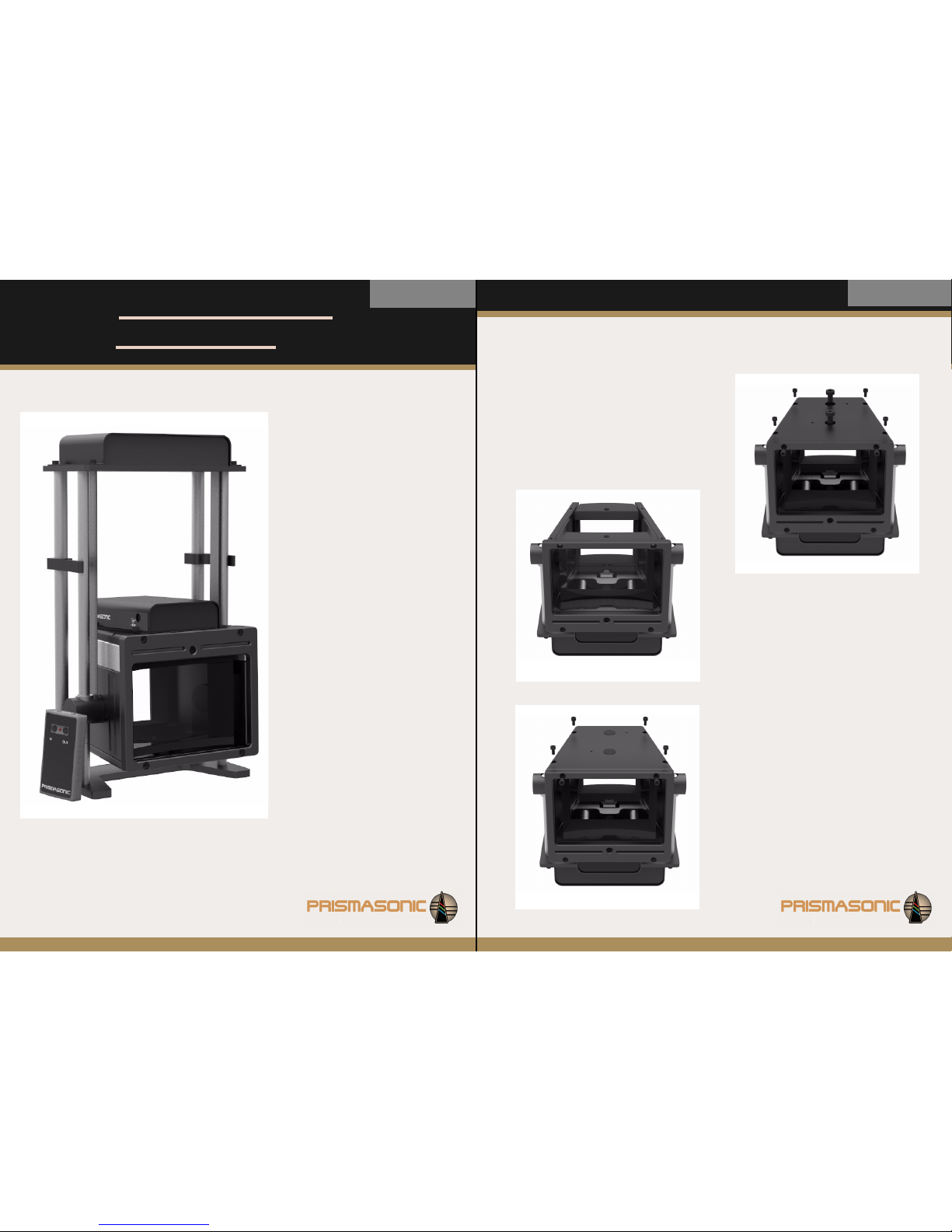
Parts list:
Lens Unit
Shipping Rail (2 pcs)
Stand Plate
Stand Rail (4 pcs)
Stand Rail Extenders (4 pcs)
Slide Lock (4 pcs)
Power Cord
Power Converter
Remote Controller
L-Wrench 2, mm
L-Wrench 3, mm
L-Wrench 4, mm
L-Wrench 5, mm
Black Cap (2 pcs)
Skt Cap Screw, M6 x 10 (6 pcs)
Instruction Manual
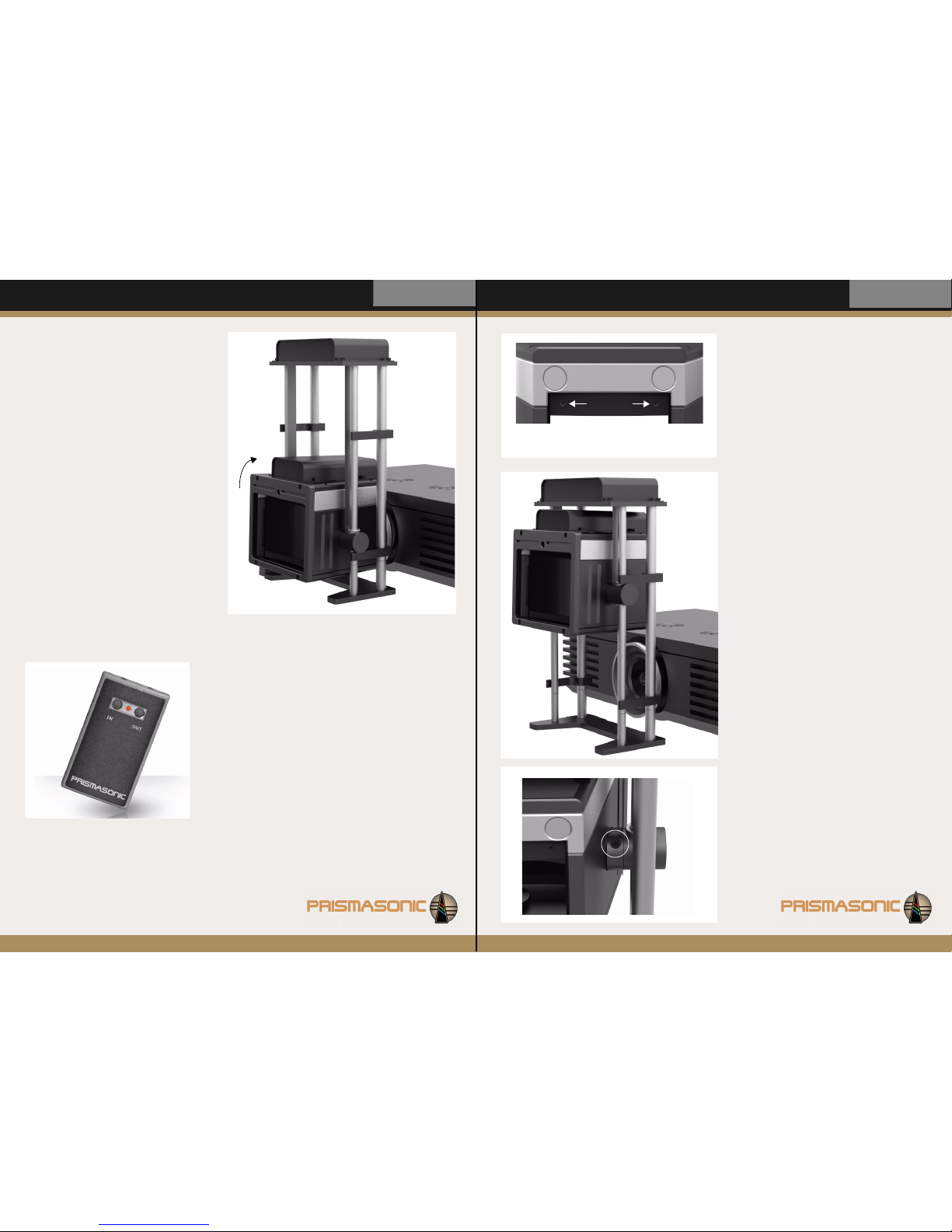
Bringing the lens into the use:
Flip the lens unit with shipping rails upside
down on a table. By using the L-wrench, 5 mm
carefully remove the delivery lock screws of
both lenses from the bottom plate (Fig 1-a).
After this release the two upper screws of front
element (Fig 1-b) by using the L-wrench, 3mm.
STEP 2
Remove the bottom plate (Fig 2) of housing by
releasing the four screws on the bottom plate
(Fig 1-c). Now carefully take off the plastic cover
coats from both sides of both lenses. Remove
also the cover coats from both IR windows of
both motor boxes.
STEP 3
Insert the bottom plate back to the housing and
prepare to affix the four screws (Fig 3-a) with L-
wrench 3mm. Tighten the screws securely. Also
insert the black caps into the slots of bottom
plate (Fig 3-b).
Now also attach the two cap screws of front plate
back to their places (Fig 3-c).
Anamorphic Lens
Cinomorph C-150R
A Picture to
Remember
Fig 3
c)
c)
a)
b) a)
a)
a)
b)
Fig 2
Fig 1
b)
b)
c)
a) c)
c)
c)
a)

Setup Instructions Anamorphic Lens
Cinomorph C-150R Setup Instructions
STEP 4
Flip the lens unit back upright. Remove the
motor cover of motor box by releasing the four
cap screws using the L-wrench 3 mm (Fig 4-a).
After this, using the L-wrench, 4 mm, remove the
both shipping rails, shown with arrows in a Fig 4,
by releasing the each cap screw, M6 x 10,
locating under the motor cover (Fig 4-b).
STEP 5
Now, refer to Fig 5, attach the four stand rails to
stand plate with cap screws, M6 x 10. Make sure
the 12 mm Ø rails and 15 mm Ø rails are placed to
the correct spots on a stand plate. Tighten screws
in the slots of stand plate securely using the L -
wrench, 4 mm.
in this step also insert the four slide locks to their
places on a stand rails 15 mm Ø. Make sure the
each lock pair is in a same plane on a rail. The final
positions to the locks will be defined by your setup,
and thus they may need to be repositioned later,
when setting up the system.
NOTE: Some setups may need an extra height to the
slide travel. In order to extend the travel, use the rail
extenders, depending on a requirement, in one end
only, or in both ends of main rails (Fig 5). The set of
extension rails increases the slide travel for 4.5 cm.
The each extension rail is screwed securely into the
main rail, after which it is working as a single, longer
stand rail.
STEP 6
Now very carefully set the lens unit onto the
stand plate with stand rails as presented in Fig 6,
so that 12 mm Ø rails go through the linear
bearings of lens drums on sides. Refer to Fig 6,
turn the upper slide locks aside from the lens
when inserting the lens. Connect the lens unit to
four rails with cap screws, M6 x 10 (Fig 6-a).
Tighten the screws securely using the L -wrench,
4 mm
Finally attach the motor cover back with four cap
screws using the L-wrench 3 mm (Fig 6-b).
Your lens is now ready for setting up !
Fig 7
STEP 7
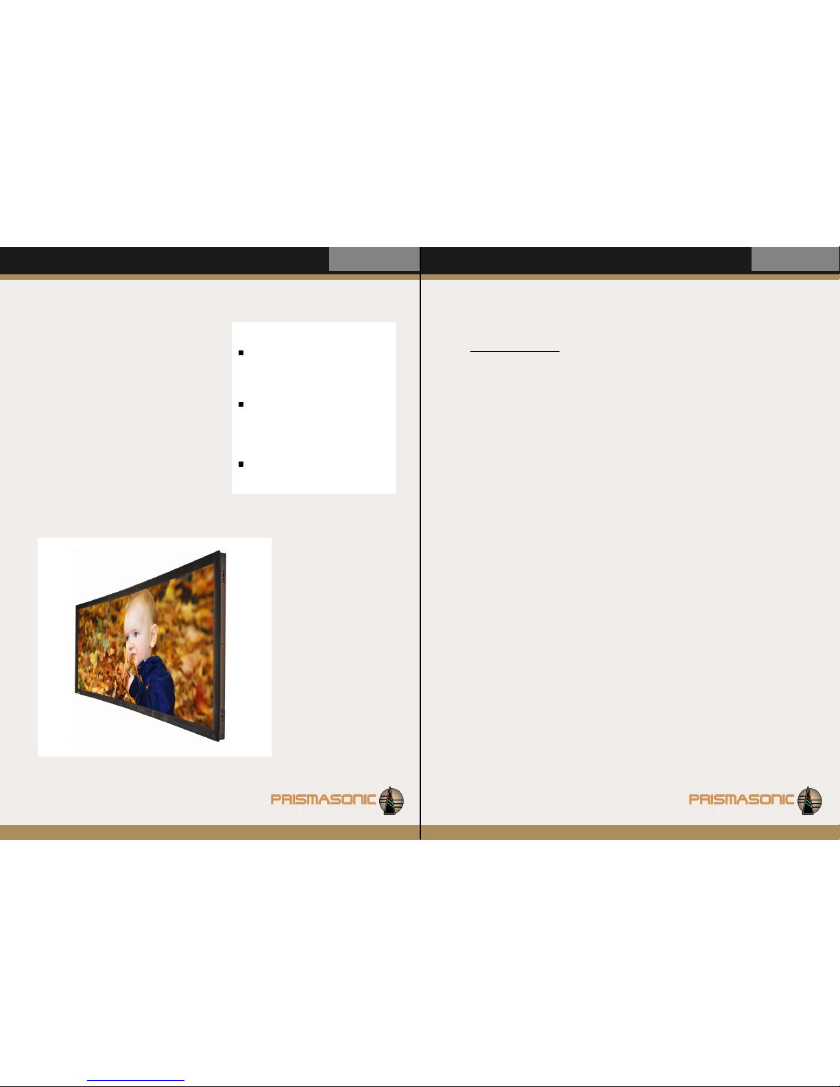
Make sure the projector is turned on. It is
helpful to have a picture that fills the entire
panel of 16:9 projector. With a 2.40:1 source
material the vertical expand is good to be
performed to the picture at this step (Fig 7).
Now carefully adjust the focus of projector.
Also make sure the image is symmetrically in
the center of the 2.40:1 screen.
Setting up the system:
Anamorphic Lens
Cinomorph C-150R
Fig 4
a) a)
a)
a)
b)
b)
Fig 5
Fig 6
a) a)
a)
a)
b)
b)
b)
b)
Setup Instructions Anamorphic Lens
Cinomorph C-150R
STEP 8
Make sure the power plug has been connected to
the socket of lens motor box, locating on the rear IR
window.
Carefully position the lens with a lift stand in front
of the projector, with the small opening closest to
the projector lens and the large opening pointing
towards the screen.
Now press and hold the ‘in’ button of remote
controller until the lens has reached the level of
projector’s optics. Make sure the entire beam fits
centered within the two lenses (Fig 8). Lower, raise,
turn and tilt the lens until the desired height and
angle is reached, and the picture is symmetrically in
the center of the 2.40:1 screen.
Now move the lower pair of slide locks into the
contact with stand drums, exactly as illustrated in
Fig 8. Make sure the locks are exactly at the same
plane.
NOTE: The optimum symmetry for the projected
picture can only be found by tilting the lens to the
direction of the beam
STEP 12
In case the friction based tilt adjusting mechanism
(Fig 12) become too loose, it is possible to get it
tightened with the set screws of stand drums on
both sides of lens. Use the L-wrench, 4 mm for
tightening the screws.
STEP 9
Switch the power cord from lens lift system to the focus
control socket. Now adjust the lens focus. Using the
remote control, press and hold “in” or “out” (Fig 9) until
the 2.40:1 picture gets focused. It is helpful to use a test
grid to monitor when the horizontal and vertical lines in
picture become in focus simultaneously. After the focus
has been adjusted, switch the power cord back to the
lens lift system.
Fig 12
Setup Instructions
STEP 11
For the presentation of native 16:9 material press
and hold the ‘out’ button of remote controller until
the lens has completely moved aside from the beam
(Fig 11). Make sure the lens do not hit the plate of
motor box. If needed use the rail extenders to get
more travel to the lens.
Now move the upper pair of slide locks into the
contact with stand drums, exactly as illustrated in
Fig 11. Again, make sure they are in a same level
with each other. Finally, after the correct position is
found, tighten the set screws of all four slide locks
by using L-wrench, 4mm.
Fig 10
STEP 10
In case there exists imbalance in focus between
the left and right sides of picture, it is possible to
correct it by fine rotating the small lens. Using the
L-wrench, 2 mm, by opening the other set screw
and closing the other for the same amount (Fig
10), it is possible to rotate the small lens to either
direction and thus find the perfect balance
between the sides. Good adjusting step for the
screws of this iterative tuning process is quarter
round at the time, after which every time the
picture is refocused by the lens.
If the imbalance gets worse after first iteration
round, this indicates that the lens has to be
rotated to other direction in order to find the
calibration sweet spot.
Anamorphic Lens
Cinomorph C-150R
Fig 8
Fig 9
Fig 11
Setup Instructions Anamorphic Lens
Cinomorph C-150R Setup Instructions
MAKE YOUR NOTES HERE
SPECIAL NOTES:
Use the lens only in an upright position.
The lift system does NOT work, and may
get damaged,if the lens is used upside
down.
If, however, the lens is flipped upside
down e.g. for the installation of rail
extenders, make sure the lens has been
driven up, and is in contact with the
motor plate of slide.
Save the shipping rails, and use them in
case of re-shipment of the lens
Anamorphic Lens
Cinomorph C-150R
Yo u ’r e d o n e . Enjoy your new 2.40:1 picture!
Maintenance:
Your Prismasonic lens was designed to require very
minimal cleaning. It is best to only wipe the lens
housing with a clean, damp, soft cloth when
needed.
Cleaning the optics:
Only use optically safe lens cleaning solutions and a
clean, lint-free cloth certified for cleaning of lens
materials. In order to clean the optics from both
sides, the bottom plate can be temporarily
removed.
Other Prismasonic Projector Accessories manuals


