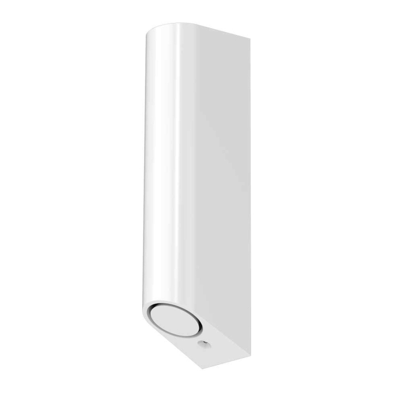
Prismatibro Prisma Daps 2000 User manual

1
DIGITAL ACOUSTIC
PEDESTRIAN SIGNAL
INSTALLATION
MANUAL
2000

2
EXPLODED VIEW
A
B
C
D
E
F
G
H
I
J
K
L
M
N
O
P
Tactile direction arrow
Top cover
LED light ring
Service hook
Cable
Terminal
Electronic module
LED in front
Front
Relief symbols (mounting example)
Housing
Decorative prole
LED protection lens
Bottom lid
Vibrator plate
Vibrator plate with push button

3
OPTION 1
When the unit is mounted directly onto
the mast access panel from the rear.
1. Remove mast access panel from the pole.
2. Thread the cable Ethrough the panel.
3. Screw the unit onto the panel from the rear
of the panel, using M6 screws.
4. Connect the cable Eto the mast terminals.
5. Ret the mast access panel with the unit mounted.
6. Test signal.
7. Remove the top cover Btogether with the
LED light ring C, turn out the service hook D
and place the lid on the service hook during
installation – see picture below hole pattern.
8. Install relief symbols J.
9. Install the top cover and the LED light ring.
10. Fasten the tactile direction arrow Ain correct
walking direction (p. 6).
M6
M6
Ø 7mm
Ø 7mm
Ø 4mm
Ø 4mm
Ø 13mm
HOLE PATTERN
Upon request a real size hole pattern sticker Zcan be provided along with the ordered products.
Fasten the hole pattern on the pole and drill the holes.
ZOPTION 2
When it is impossible to install the
screws from the rear.
1. Remove the top cover Band the LED light
ring
C, turn out the service hook Dand place
the cover on the service hook during installation
– see picture below hole pattern.
2. Disconnect the cable connectors from the
electronic module G.
3. Slide out the electronic module Gand front I.
4. Push the LED protection lens Mup.
The mounting holes are now accessible.
5. Thread the cable Einto the mast.
6. Mount the housing Konto the mast.
7. Replace the LED protection lens M, slide in
the electronic module Gand front I.
8. Connect the cable Eto the mast terminals.
9. Test signal.
10. Install relief symbols Jand tactile direction
arrow
A(p. 6).
11. Fold back the service hook D, install
top cover Band LED light ring C.
INSTALLATION
[Not actual size]
D
100-170, 150-240 V
T
U
V
•
•
W
X
Q
S
R
18-24 V
TT
UU
VV
•
•
•
•
WW
XX
28-49 V
Q
Q
R
SS
R
S
T
Connection push front
Connection vibrator
Q
R
U
V
W
X
Main connection
Fuse direct supply
Connection NFC module
USB connection
Connection LED light ring
Connection external
push button
•Not in use

RED Red lamp phase
BLUE Neutral
GREY Green lamp phase
WHITE Direct constant supply* (+/~ xx V)
BLUE/WHITE Direct constant supply* (0V)
PINK Output signal via Relay K2
BLACK/WHITE Common referense, point for inputs
BLACK Wire 1, Night option signal
VIOLET Wire 3, Extra option signal
ORANGE Supply to the Demand signal. Internal wire strap to 40
BROWN Demand signal via relay K1. Internal wire strap to 23
BEIGE External loudspeaker +
TRANSPARENT External loudspeaker -
4
5
6
11
10
41
21
22
30
31
51
50
20
PINK Output signal via Relay K2
VIOLET Wire 3, Extra option signal
1
2
3
4
5
6
7
4
5
6
11
10
30
31
GROUNDING CABLE IS NOT USED SINCE THE
Prisma Daps 2000 IS DOUBLE INSULATED.
21
4
5
6
To connect the 13-wire cabling to a 7-wire connector - see picture below.
Pink, violet, beige
and transparent are
not used.
Keep the isolation
protection on these.
Prisma Daps 2000•M: 6 wires
8-wires cabling: Just like 6-wires cabling with two additional wires
1
2
3
RED Red lamp phase
BLUE BLUE Neutral. Internal wire strap to 10 and 20
GREY Green lamp phase
BLACK Wire 1, Night option signal 21
BROWN Demand signal via relay K1 31 Internal wire strap to 23
WHITE Direct constant supply* (+/~ xx V) 11 Internal wire strap to 30
* Separate direct constant supply - not through the
lamp cable
BLACK
BROWN
WHITE
ORANGE
RED
BLUE
BLACK/WHITE
BLUE/WHITE
GREY
22
41
CABLE DESCRIPTIONS
Prisma Daps 2000•L: 13 wires. 13 wires is standard for new intersections.
20

5
CONNECTION
Push Button
1
Push
Button 2
NFC/RFID
LED
light ring
LED
in front
USB
AC/DC
Direct
constant
supply*
PowerAmp
Internal LS
Vibrator
driver
PowerAmp
External LS
Opto
Opto
Opto
Opto
4
21
22
4
23
11
K1
K2
+
-
10
30
20
6
5Opto
31
32
40
41
42
51
50
External Loudspeaker
[Option]
Output K2 (NC)
Output K2 (NO)
Input K2 (IN)
Output K1 (NC)
Output K1 (NO)
Input K1 (IN)
Common 0V ref.point direct constant supply*
Common ref. point for opto inputs
Common ref. point for red and green
Green pedestrian light
Red pedestrian light
Night option signal
Wire 1 in programming equipment
Extra option signal
Wire 3 in programming equipment
Wait signal (or option)
Wire 2 in programming equipment
Direct constant supply*
Normally used as
RFID/special signal
Normally used as
demand signal
NOTE
• 13-wires is recommended as a standard cabling for new intersections.
• With 28-49V AC/DC, and 18-24V AC/DC, 13-wires can be used if the common reference point for red and green lights can be connected
to the common reference point for Direct Constant Supply.
• Adapter cabling is used when exchange of the electronic module from Prisma Daps 1000 or Prisma Daps TS-900-series to Prisma Daps 2000.
• A customized cabling can be provided on request.
Depending on the number of wires in your cabling, functions can possibly be limited.
Example of functions that might not be usable are relay 2, wire 3 and external loudspeaker.
* Separate direct constant supply - not through the lamp cable
ERROR HANDLING
Visit: www.prismatibro.se/en/error-da
Or: Scan QR-code

6
FITTING RELIEF SYMBOLS AND DIRECTION ARROW
Purpose • These symbols have been designed specically to allow people with impaired vision to get an overview of the intersection
and in which direction to walk.
Placing • The relief symbols should always be placed facing the pavement. The decorative proles should be placed on the opposite side,
facing the road. If the unit is placed on a median/island there should be decorative proles on both sides.
The exception to this is if the median is so wide that there is a path or bicycle lane running through it. If this is the case, then the relief symbols
should be tted to indicate the type of trac that could be expected
Relief symbols should never be used on the bicycle path signal.
Fitting relief symbols • The housing has slots for the relief symbols and decorative proles, and they are secured by the top cover and
bottom lid. There are 7 dierent symbols and 3 plain pieces of dierent lengths to assure that the slot in the acoustic signal is always full and the
symbols are held solidly in place. The number of symbols required depends on the type of trac lanes at the crossing. The “START” and “ARRIVAL”
symbols must always be included. These symbols give people with impaired vision a tactile picture of the intersection and the direction of the crossing.
Therefore it’s crucial that they are turned and positioned absolutely correctly.
The “START” symbol, nr 1, should always be at the bottom and then the dierent symbols necessary are inserted in their respective order.
The “ARRIVAL”symbol, nr 7, should always be at the top.
Double-check the position of the relief symbols! See image description below.
IMPORTANT!
Always check where the acoustic pedestrian signal is placed. For example: If a bicycle path is located in parallel with the walkway, but you need
to cross it to reach the acoustic pedestrian signal, the symbol “bicycle path” should not be included in the relief symbols, because the bicycle
path has already been crossed.
Mounting tactile direction arrow • The direction arrow is tted on the top cover and must be
aligned in the correct direction. A double arrow is used on units placed on a median/island.
The arrow is tted into the circular recess on the top cover and attached by Silicone glue.
Make sure it is pointed in the correct direction, before you attach it.
RELIEF SYMBOLS
START!
BICYCLE PATH
TRAMS · TRAINS
BICYCLE PATH
Indicates the opposite pavement
EXAMPLE
Mounted for right-hand trac
You are here
Always placed at the bottom
The arrow shows you the walking direction
Bicycles from both directions
Indicates rail trac from the left
Indicates bicycles from the left
MEDIAN · ISLAND · REFUGE
VEHICLE TRAFFIC
Indicates vehicular trac from the right
ARRIVAL

7
Prisma Daps 2000 has an
electrical design to meet all
requirements for constant
power supply.
CONSTANT POWER SUPPLY* CONTROL I/O LAMP I/O
18-24V AC/DC 10–50V AC/DC 10–50V AC/DC
28–49V AC/DC 17–50V AC/DC 17–50V AC/DC
100–240V AC 50–170V AC 50–170V AC
100–240V AC 120–250V AC 120–250V AC
Protection Class Class II, double insolated
IK Rating IK10, models without vibrator • IK08, models with vibrator
IP Classication IP55
Power Consumption Walk: 2,5-10W • Tram: 7,5-10,5W
Locator sound frequency 880 Hz
Min & Max volume 0 dBC, 30-87 dBC
With connecting external loudspeaker: 100 dBC
Light Character Yellow, approx. 590nm wavelength
Light Output LED in front: 9 x 4000 Partial FLUX
LED light ring: 32 x 4000 Partial FLUX
Temperature Range -40° F to 158° F
-40°C to +70°C
Humidity 0-100% RH
Cabling Prisma Daps 2000•L: Standard 13-wire cabling.
Prisma Daps 2000•M: Standard 6 or 8-wire cabling.
Adapter cabling is used when exchange of the electronic module from Prisma Daps TS-900 series,
Prisma Daps 1000 to Prisma Daps 2000. Customized cabling on request.
Colour Blue anodization • Gold anodization • Yellow varnished • Gray varnished • Black-vanished
Other colours on request
Anti-grati Possible to add on all colours
Housing
Push Front
Aluminum
No moving parts
Lids
Arrows
Polyamide PA66
Dimensions
Diameter to t the pole 114 mm, 4.5 Inch
Weight ≈ 2,5 kg
Force to push the front 1 ton 0.22 lbs
Push front mechanical life ≈ 10 million presses
Warranty 5 year
TECHNICAL INFORMATION
PROGRAMMING
Prisma Daps 2000 is programmed from the Android App: Prisma Daps.
Choose your unit - Set your functions - Transfer settings and les.
Prisma Daps 2000•L is equipped with a NFC antenna in the top cover for wireless
communication, without opening the Prisma Daps unit.
You can transfer via the USB-port, which is placed behind the LED in front,
on both Prisma Daps 2000•L and Prisma Daps 2000•M.
READ FULL INFORMATION ON PROGRAMMING IN THE APP MANUAL
Manual for Prisma Daps Android Application is found at www.prismatibro.se/en/ladda-daps/
*Separate direct constant supply - not via the lamp cable
1
Prisma Support
DIGITAL ACOUSTIC
PEDESTRIAN SIGNAL
ANDROID-APP
MANUAL
VERSION 2.7
2000
125 mm
112 mm
284 mm
125 mm
274 mm
112 mm

© PrismaTibro · 9202-EN · 200914
THEREFORE PRISMATIBRO
QUALITY & SERVICE WARRANTY 5 YEARS
30 YEARS OF EXPERIENCE
GLOBAL AND LOCAL
PrismaTibro has nearly three decades of experience in developing and
manufacturing unique, high quality products with advanced and reliable technology.
Part of Addtech-group since July 2018.
We are ISO 9001 certied to ensure high quality products, services and
customer support.
Our four product areas are pedestrian signals, deection indicators, push buttons
and LED street lights.
CSR, corporate social responsibility: As a company, we want to reach out and
help the people in Sweden and around the world with the love of God.
We support dierent projects that helps children by building new schools,
providing clean water and diverting them from a life in crime. There is so much
we can do to help, and we are committed to contribute as much as we can.
Aluminum housing, top and
bottomlids in polyamide, a front
with no moving parts.
Prisma Daps Pedestrian Signals
are vandal proof.
A monitoring system continuously
measures the currents of green and
red phases – walk or don’t walk – in
order to guarantee the safety of the
pedestrian.
Our pedestrian signals will never
sound green during red phase.
Buying products from PrismaTibro
is a safe investment. They will work
day in and day out, year after year.
Our pedestrian signals can be linked
up to almost any trac control system.
They are equipped with dierent
software settings depending on the
local requirements.
Table of contents


