pro bel VISTEK V1667 User manual

1
VISTEK V1667,V1667/SY
&V1667/SY-VHS 12-BIT
PAL/NTSCTO SDIADAPTIVECOMB
FILTERDECODERUSER GUIDE
www.pro-bel.com

VISTEKV1667, V1667/SY & V1667/SY-VHS
12-bit pal/ntsctosdi adaptive
comb filterdecoder
2Issue 3
Contents
1. GENERAL DESCRIPTION........................................................................................4
2. INSTALLATION.........................................................................................................5
2.1 Rear Panel Layout and Signal Connections..................................................5
2.2 Frame Synchroniser Module (Optional).........................................................6
2.3 Frame Synchroniser Delay..............................................................................6
2.4 Insertion Delay.................................................................................................6
3. FRONT PANEL LAYOUT..........................................................................................7
3.1 Page/Parameter Map.......................................................................................8
4. FRONT PANEL DESCRIPTION (NORMALOPERATION).......................................9
4.1 +V Indicator......................................................................................................9
4.2 REM Indicator...................................................................................................9
4.3 Video Standard Indicators /Selection of Video Standard............................9
4.4 Parameter Indicators and Adjustment...........................................................9
4.5 Remote /LocalSwitch..................................................................................10
5. TIMINGPAGE(FRAME SYNCHRONISER)............................................................11
5.1 Timing Page Entry.........................................................................................11
5.2 Timing Parameter Selection and Adjustment..............................................11
5.3 Timing Page Exit............................................................................................12
6. ENGINEERING PAGE.............................................................................................13
6.1 Engineering Page Entry................................................................................13
6.2 Engineering Parameter Selection and Adjustment.....................................13
6.3 Engineering Page Exit...................................................................................14
7. TECHNICAL SPECIFICATION................................................................................15
8. APPENDIX...............................................................................................................16
8.1 On Board AdjustableComponents..............................................................16
8.2 On Board Switches........................................................................................16
8.3 VHS Input Option...........................................................................................17
8.3.1 Selection ofVHS Decode Mode.........................................................17
8.3.2 Parameter Selection and Adjustment.................................................18

VISTEK V1667,V1667/SY & V1667/SY-VHS
12-bitpal/ntscto sdiadaptive
comb filterdecoder
HU-V1667&SY&SY-VHS 3
8.4 An Introduction to Vislock Processing........................................................18
8.4.1 Whatis VisLock?................................................................................18
8.4.2 Howdoesit work?...............................................................................18
8.4.3 Does the added data degrade my picture?.........................................19
8.4.4 Will digital equipment in the path pass the VisLock signal?................19
8.4.5 Howis VisLock Implemented?............................................................19

VISTEKV1667, V1667/SY & V1667/SY-VHS
12-bit pal/ntsctosdi adaptive
comb filterdecoder
4Issue 3
1. GENERAL DESCRIPTION
The V1667 is a12 bit broadcastqualitymulti-standard adaptive combfilter decoder, and formspart ofthe
Vistek V1600 modular range of interface products.The 3U x250mm card maybe fitted into eitherthe V1601
(1U) or V1603 (3U) 19” rack mountable enclosures,fromwhich it derives itspower. All signal inputs and
outputsare made via a passive rearmodule.
In its basic form,without aFrameSynchroniserfitted (V1667 product), the unit converts an analogue colour
encoded composite video input to a 270Mbit component Serial DigitalVideo (SDV) output standard.
One oftwo FrameSynchroniser modules maybe optionallyfitted to the decoder. The standard Frame
Synchronisermodule (fitted on the V1667/SY product) permits the output of the unit to be timed up to an
external reference, with auserprogrammable offset of up to + 127 lines relativeto the reference. The
alternativemodule (fitted on the V1667/SY-VHS product) hasthe samefunctionalityofthe standard
synchroniser module, but also offersthe facilityto decode non-timebase corrected signals, specificallythe
output ofa VHS tape recorder.
VisLock processing maybe optionallyfactoryfitted to the card. VisLock processing is apatented method of
converting an NTSC composite analogue signal to serial digital form(within the V1667),then subsequently
re-converting backto NTSC (within a VistekV1668 encoder) with negligible lossof picture quality.
The V1667 has ahigh impedancelooping input, into which the analogue colour encoded input ispresented.
The card will detect, and consequentlyautomaticallydecode, anyof the standardslisted below:-
PAL B, G, I, M, N
NTSC M, NTSC JAPAN
NTSC 443
The decodermayalsobe forced into anyone ofthe specified standards,although it isgenerally
recommended that the user leave the card set in automatic (AUTO) mode.
The V1667 hasfour 270Mbit component Serial Digital Video (SDV)outputs.
Front panel controlsenable the user to set up/adjustvarious operating parameters,and ifaFrame
Synchroniseroption is fitted theymaybe used to time the unit into an installation.
Allparameter settings,for each standard, are stored in non-volatile memory.Thusaunit maybe powered
down without the settingsbeing lost.
VISTEK V1667,V1667/SY & V1667/SY-VHS
12-bitpal/ntscto sdiadaptive
comb filterdecoder
HU-V1667&SY&SY-VHS 5
2. INSTALLATION
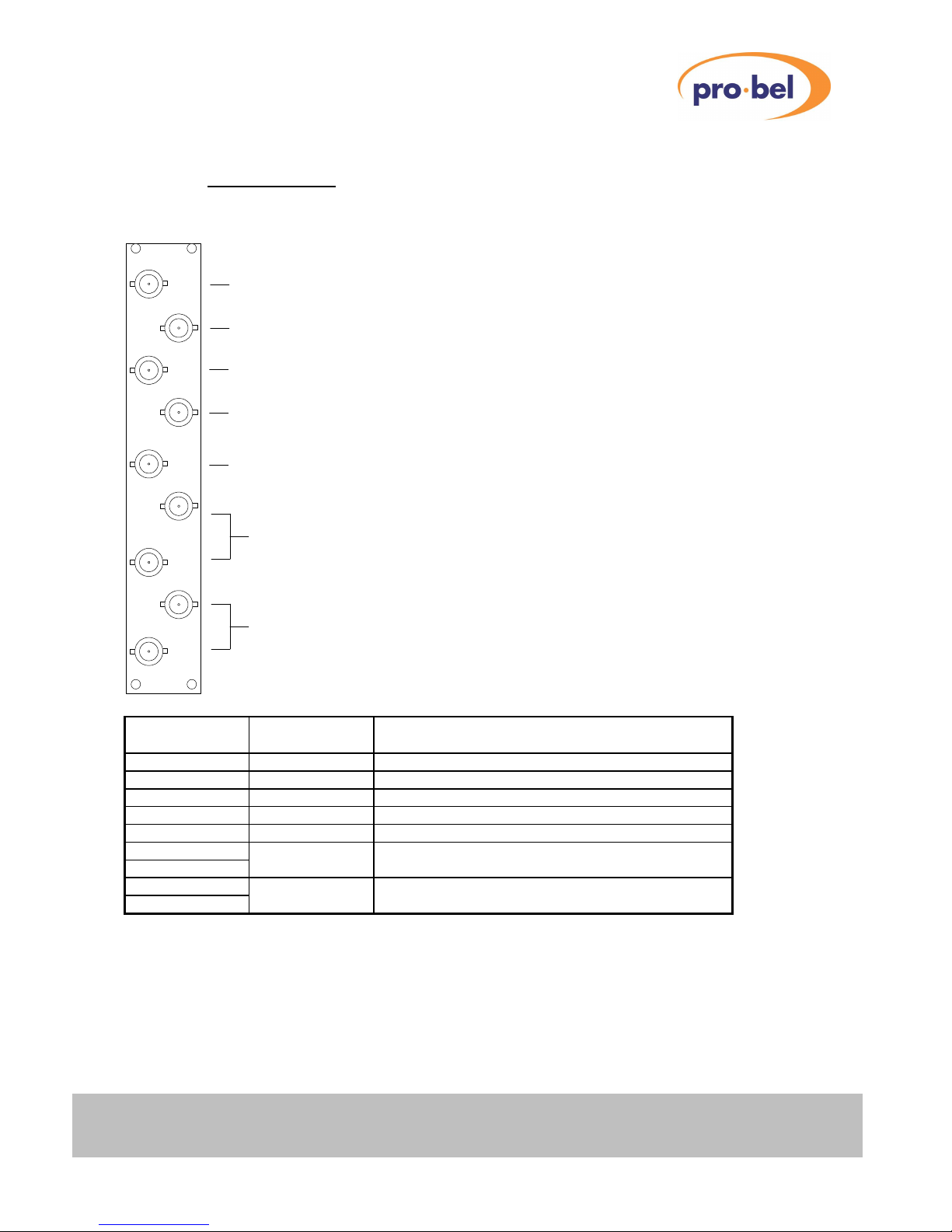
2.1 Rear Panel Layout and Signal Connections
SD
(IN)
SD 1
(OUT)
SD 2
SD 3
1
2
3
4
5
SDI Output 2
SDI Output 3
Analogue Composite Video (CVBS)
Looping Input
Reference Input to Synchroniser(If fitted)
DELAY-TTL O/P fromSynchroniser(If fitted)
SDI Output 1
SDI Output 4
Looping Input
BNC Connector
Input / Output
Description
Comments
SD (IN) SDI Output 1 Cable drive length:-up to 200 metres.
SD 1 (OUT)SDI Output 2 Cable drive length:-up to 200 metres.
SD 2 SDI Output 3 Cable drive length:-up to 200 metres.
SD 3 SDI Output 4 Cable drive length:-up to 200 metres.
BNC 1 DelayO/P (TTL)Onlyvalid when a synchroniser sub-module is fitted.
BNC 2 CVBS High impedance looping input.
BNC 3 Looping Input
BNC 4 Reference High impedance looping reference input.
BNC 5 Looping Input Onlyvalid when a synchroniser sub-module is fitted.

VISTEKV1667, V1667/SY & V1667/SY-VHS
12-bit pal/ntsctosdi adaptive
comb filterdecoder
6Issue 3
2.2 Frame Synchroniser Module (Optional)
A Frame Synchronisermodule maybe optionallyfitted to the V1667. It islocated into socketsP1, P2, P3 and
P4. Its presence isautomaticallydetected bythe on board micro-processorand is consequentlyintegrated
into the signal processing path.
With a Frame Synchroniser fitted, the user mayadjust the V1667 output timing relative to the reference input
byup to a maximumoffset of + 127 lines. This operation isdescribed in Section 5.2 Timing Parameter
Selection and Adjustment.
Ifa Frame Synchroniser module isfitted, but there isno reference input, then the decoder will enter a
minimumdelaymode. In this mode the synchroniserisbypassed, and the delaythrough the unit isfixed at
7µs.
See Section 8.3 VHSInput Option for a description ofthe VHS frame synchroniser option.
2.3 Frame Synchroniser Delay
When the Frame Synchroniser option isfitted there isa TTL output signal to indicate the amount of extra
delayinserted above the minimumasspecified for the unit. The signal has a constant period oftwo frames
and a variable mark space ratio which dependson the amount ofdelayinserted. The HIGH portion of the
signal indicatesthe delay.
A typical waveformis asshown below:
DELAY
2 FRAMES
Note: If the input and reference signals are asynchronous then the width of the delaypulse will vary,
and will be dependent on the relative timing of the two signals.
2.4 Insertion Delay
The insertion delaythrough the V1667 is dependent on whethera Frame Synchroniseroption isfitted.
Without a Frame Synchroniser it isdeterministic and fixed. With the Frame Synchroniser fitted there is a
delayrange, and the absolute delaywill be dependent on the relative timing between the input video signal
and the reference input.
In each case the delayismeasured between the composite video input and the input to the SDI serialiser.
Condition Unit Delay
V1667 + No Frame SynchroniserModule 7µs
V1667 + Frame Synchroniser Module 7µs(Minimum)
1 Frame + 7µs (Maximum)
VISTEK V1667,V1667/SY & V1667/SY-VHS
12-bitpal/ntscto sdiadaptive
comb filterdecoder
HU-V1667&SY&SY-VHS 7
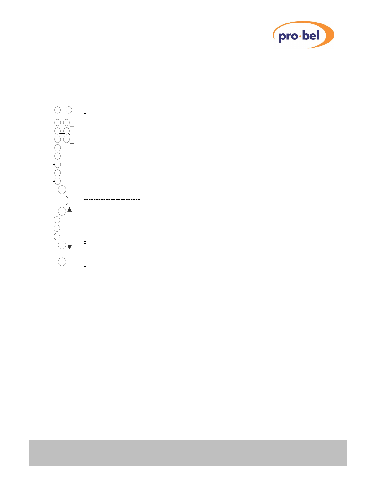
3. FRONT PANEL LAYOUT
See Section 8.3 VHSInput Option for a description ofthe VHS decoding option.
REM +V
NTSC
443
Local
Rem
V1667
12 Bit Decoder
CVBS to SDI
Select
CAL
+
-
I
M
N
Std.
VGain
CGain
Phase
Setup
PAL
Remote Control Access and Power indicators
Standard and Page indicators
Parameter indicators:
SELECT Button
UPButton
CAL / NORMALISED LED
DOWN Button
REMOTE/ LOCAL control selection
AUTO
UNCAL LED (+)
UNCAL LED (-)
A
B
C
D
E
Sig
Tim
Anc
Named for Top Page
A- Efor other Pages
VHS
VHSinput selection:-
Only available on V1667/SY-VHSproduct
The V1667 hasa versatile front panel, shown above. Commonlyused controls are directlyavailable, whilst
the less used ones are protected frominadvertent use. The panel uses the concept of Pages and
Parameters. Within each Page there are a possible 5 adjustable Parameters.
There is provision for5 pagesin total, although only3 are currentlyused. These are:
Top page (normal operation) Thisisthe normal operating page. The unit will always enterthispage at
powerup.
See 4. FRONTPANEL DESCRIPTION (NORMAL OPERATION)
Timing Page Thispage isused to adjust the Frame Synchroniser timing parameters
and input failure modes, and is accessible onlywhen a Frame
Synchronisermodule isfitted to the card.
See 5. TIMINGPAGE (FRAME SYNCHRONISER)
Engineering Page Thispage isused to make changesto the decoder processing that it is
considered the user will onlyneed to access infrequently(VITS
pass/blank, etc..)
See 6. ENGINEERING PAGE

VISTEKV1667, V1667/SY & V1667/SY-VHS
12-bit pal/ntsctosdi adaptive
comb filterdecoder
8Issue 3
3.1 Page/Parameter Map
Thistable showsall the adjustable Parameters in each Page. It maybe convenient to keep a copyclose to
the equipment.
Top Page Page 1 (SIG)Page 2 (TIM)Page 3 (ANC) ENG.
A Standard V Timing NTSC type
B Video Gain H Timing Vertical interval
C Chroma Gain Sync. I/P fail mode
VisLock1
D Phase Minimumdelay Delayline PAL
E Setup/Black Timing Reset Chroma B/W
1This control isavailable onlyifthe VisLock option hasbeen factoryfitted to the card. See Section 8.4 An
Introduction to Vislock Processing fora description ofthe VisLock processing option.

VISTEK V1667,V1667/SY & V1667/SY-VHS
12-bitpal/ntscto sdiadaptive
comb filterdecoder
HU-V1667&SY&SY-VHS 9
4. FRONT PANEL DESCRIPTION(NORMALOPERATION)
See Section 8.3 VHSInput Option for a description ofthe VHS decoding option.
4.1 +V Indicator
Thisisa green LED that isilluminated when the module ispowered.
4.2 REM Indicator
Thisyellow LED is illuminated when the module isaccessed bythe DARTremote control system.
4.3 Video Standard Indicators /Selection of Video Standard
Thisisa bankof six yellow LEDs which indicate the operating standard and the status ofthe input signal.
Please note that selection ofthe video standard via the front panel mayonlybe achieved ifthe Local /
Remote switch is set to Loc. When it isset to Rem there isa front panel lockout condition.
Selection ofthe operating standard ismade byfirst pressing the Select button until the green Standard
parameterLED isilluminated, then secondly bypressing the Up or Down buttons ( or ▼respectively) to
select the desired standard of operation.
The software allowsthe user to force anyone standard, depicted bythe relevant LED being illuminated, or to
enteran automaticdetect and decode mode, wherebythe AUTO LED will be illuminated together with the
relevant detected standard LED.
Ifthere isno input signal present, or if the input signal is ofpoor quality, then the decoder will indicate this by
flashing the selected standard LED when in force mode. When in automatic mode the AUTO LED will flash
and none of the standard LEDswill be illuminated.
4.4 Parameter Indicators and Adjustment
There are five parametersthat maybe adjusted bythe decoderin the Top Page. These are the video
standard, video gain, chrominance gain, demodulation phase and setup/blacklevel. The rowoffive green
parameterLEDs indicate which parameter has been selected, and the statusof the non-selected
parameters.
Please note that selection and adjustment ofanyvideo parameter via the front panelmayonlybe achieved if
the Local / Remote switch isset to Loc. When thisswitch is set to Rem there is a front panel lockout
condition.
Selection ofthe parameter to be adjusted is made byrepeatedlypressing the Select button until the relevant
green parameter LED is illuminated. The software cycles through each parameter in turn plus a sixth
‘dummy’ position, within which no parameter is selected (no LED illuminated). Thishelpsto prevent
accidental mis-alignment ofa parameter.
Afterselecting the desired parameter, adjustment ismade byusing the Up and Down buttons ( or ▼
respectively). If the selected parameter isadjusted awayfromthe calibrated position the green Cal LED will
be extinguished, and one of the red LEDs(+ or -)will be illuminated, dependent on whether the chosen
parameterhas increased or decreased (Note: anynon-selected parameter that hasbeen adjusted awayfrom
itscalibrated position will flash at lowdutycycle). To reset the selected parameterto itscalibration position
depress the Up and Down buttons( or ▼)simultaneously.

VISTEKV1667, V1667/SY & V1667/SY-VHS
12-bit pal/ntsctosdi adaptive
comb filterdecoder
10Issue 3
Adjustment ofthe video standard (Standard) is described in the section entitled 4.3 Video Standard
Indicators / Selection of Video Standard.
Video gain (VGain) maybe increased bypressing the Up button ( ) or reduced bypressing the Down
button (▼) . Video gain amplifiesor attenuates all three of the component signals (Y, Cb, Cr) afterthe
demodulation process and each bythe same ratio.
Video gain Max200%
Cal. 100% Resolution 0.2 % steps
Min 0%
Chrominance gain (CGain)maybe increased bypressing the Up button ( ) orreduced bypressing the
Down button (▼). Chroma gain amplifies orattenuatesboth ofthe colour difference signals(Cb, Cr) after the
demodulation process and bythe same ratio.
Chroma gain Max200%
Cal. 100% Resolution 0.2 % steps
Min 0%
Demodulation phase (Phase)maybe adjusted either side ofthe calibration position byusing the Up and
Down buttons ( and ▼).
Phase adj. Max+45°
Cal. 0° Resolution 0.3° steps(approx.)
Min -45°
The luminance output black level (Setup) ofthe signal maybe adjusted eitherside ofthe calibration position
(0mV black level in all standards)byusing the Up and Down buttons( and ▼).
Setup Max+100mV
Cal. 0mVResolution 0.75mV steps(approx.)
Min -100mV
Please note: this adjustment is made after a nominal 54mVpedestal hasbeen removed from525 line
standard inputs(excluding NTSC Japan).
4.5 Remote /LocalSwitch
The V1667 maybe controlled locallyvia the front panel, hence thisswitch will be set to Local. Alternatively,
the card maybe controlled via the DARTremote control system, in which case the switch will be set to Rem.
When in the Remposition the front panel islocked out ie. it isnot possible to modifythe video standard orto
make signal parameter adjustments.

VISTEK V1667,V1667/SY & V1667/SY-VHS
12-bitpal/ntscto sdiadaptive
comb filterdecoder
HU-V1667&SY&SY-VHS 11
5. TIMINGPAGE (FRAME SYNCHRONISER)
See Section 8.3 VHSInput Option for a description ofthe VHS decoding option.
5.1 Timing Page Entry
Press the Select button and hold in, followed bythe Down (▼) button. Entryto the Timing Page will occur
immediately, and will be indicated bythe Tim pair ofLEDs(PAL M and 443)flashing simultaneously.
Note: The Timing Page mayonly be accessed if there isa Frame Synchroniser Module fitted to the card.
5.2 Timing Parameter Selection and Adjustment
There are 4 adjustable parameters defined in the Timing Page. These are defined in the table below:
Parameter
A V Timing Offset
B H Timing Offset
C SyncFail Mode
D Minimumdelay
E Timing Reset
Selection ofthe parameter to be adjusted is made byrepeatedlypressing the Select button until the relevant
green parameter LED is illuminated. Then use the Up ( ) and Down (▼)buttons to adjust the chosen
parameteras defined below.
To reset the chosen parameter to itscalibration position depressthe Up ( ) and Down (▼)buttons
simultaneously.
The output of the decoder is verticallyco-timed to the reference input when V Timing Offset isin the Cal.
position (Green Cal. LED illuminated). Ifrequired the output maybe advanced ordelayed with respect to the
reference bya maximumof127 lines.
V Timing Offset Max +127 lines
Cal. 0 linesResolution 1 line
Min - 127 lines
The output of the decoder is horizontallyco-timed to the reference input when H Timing Offset isin the Cal.
position (Green Cal. LED illuminated). Ifrequired the output maybe advanced ordelayed with respect to the
reference bya maximumof+ 1/2 line.
H Timing Offset Max + 1/2 line
Cal. 0 line Resolution 37 ns
Min - 1/2 line

VISTEKV1667, V1667/SY & V1667/SY-VHS
12-bit pal/ntsctosdi adaptive
comb filterdecoder
12Issue 3
The Frame Synchroniser offersthree modesofoperation when the input signal fails/disappears(Sync Fail
Mode). These are:
Sync Fail Mode ()Freeze picture.
Cal. Freeze picture for3 seconds, then cut to black
(▼)Cut to black.
The synchronisersub-module maybe bypassed byentering the Minimum Delay mode.
MinimumDelayMode Cal. LEDON Force MinimumDelay.
OFFNormal synchroniser functionality.
Allofthe timing parametersmaybe reset to their respective normalised positions byfollowing the procedure
described below:
1Select the Timing Reset parameter.
2Depressthe Up ( )and Down (▼) buttons simultaneously.
Successful timing reset will be indicated bythe Timing Reset LED (D) being extinguished and the V Timing
Offset LED (A) illuminating.
5.3 Timing Page Exit
Press the Select button, followed bythe Down (▼) button. The decoder will exit the Timing Page
immediately, and resume normal front panel operation.
Ifthe unit isleft in the Timing Page for more than five minutes, during which no button hasbeen pressed,
then the decoder will timeout fromthis mode and revert to normal front panel operation.

VISTEK V1667,V1667/SY & V1667/SY-VHS
12-bitpal/ntscto sdiadaptive
comb filterdecoder
HU-V1667&SY&SY-VHS 13
6. ENGINEERING PAGE
See section 8.3 VHS Input Option for a description ofthe VHSdecoding option.
6.1 Engineering Page Entry
Press the Select button and hold in, followed bythe Down (▼) button. Keep both buttons depressed for 5
secondsuntil all six yellow standard LEDs become illuminated simultaneously. Thisindicatesthat the
decoder has entered the Engineering Page.
6.2 Engineering Parameter Selection and Adjustment
Scroll around the five parameters using the Select button. The engineering parameter functions maybe
switched ON and OFF byusing the Up and Down ( and ▼) buttonsrespectively. Engineering parameters
are defined as:-
Parameter
(Panel Legend)
Cal.
LED
Engineering Page
Parameter Function
Comments
A ON
OFF
NTSC
NTSC Japan
Default (1)
B ON
OFF
Passvertical interval data
Blankvertical interval data
Default 625
Default 525
C ON
OFF
VisLockprocessing enabled
VisLockprocessing disabled
Default (2)
D ON
OFF
Adaptive delayline PAL
Simple PAL
Default all PAL standards
Default all other standards
E ON
OFF
Chrominance band passfilter.(3)
All 5 LEDs Depressthe + and - buttonsfor 5 secondsfor Factory Initialisation ofallparameters
in all standards (except timing parameters, which maybe normalised within the timing
page). After successful FactoryInitialisation the decoder will automaticallyresume
normal front panel operation.
(1)NTSC orNTSC Japan selection is onlyavailable when in the NTSC standard setting.
(2)See Section 8.4 AnIntroduction to Vislock Processing foradescription ofthe VisLockprocessing
option. This control isavailable onlyifthe VisLock option has been factoryfitted to the card.
(3)Use the Up and Down ( and ▼)buttonsto adjustthe bandwidth of the chrominance band passfilter.
Adjustment range isbetween 1 (narrowest) and 6 (widest), and isindicated bythe +, Cal. and – LEDs.
LED Filter 1 Filter 2 Filter 3 Filter 4 Filter 5 Filter 6
+ OFF OFF OFFONON ON
Cal. OFF ON ON OFF OFF ON
- ON OFF ON OFF ON OFF

VISTEKV1667, V1667/SY & V1667/SY-VHS
12-bit pal/ntsctosdi adaptive
comb filterdecoder
14Issue 3
6.3 Engineering Page Exit
Press the Select button, followed bythe Down (▼) button. The decoder will exit the Engineering Page
immediately, and resume normal front panel operation. Ifthe unit isleft in the engineering page for more
than five minutes, during which no button hasbeen pressed, then the decoder will timeout fromthispage and
revert to normal front panel operation.

VISTEK V1667,V1667/SY & V1667/SY-VHS
12-bitpal/ntscto sdiadaptive
comb filterdecoder
HU-V1667&SY&SY-VHS 15
7. TECHNICAL SPECIFICATION
Analogue Input(Looping)
Format PAL B, G, I, M, N, NTSC M, NTSC Japan, NTSC 443
Level 1V p-p composite (terminated)
Connector BNC
Impedance 75 (external)
Return loss> 35dBto 5.5MHz
Reference Input (Frame Synchroniser fitted)
Format PAL B, G, I, M, N, NTSC M, NTSC Japan, NTSC 443
Level Standard level Blackand Burst (or 1V p-p composite)
Connector BNC
Impedance 75 (external)
Return loss> 35dBto 5.5MHz
Serial (SDV) Outputs (4)
Format EBU Tech.3267 ANSI / SMPTE T14.22/082
Data rate 270 Mb/s
Connector BNC
Impedance 75
Return loss> 15dB5-270MHz
Amplitude 800mVp-p (terminated)
DC offset 0V +/-0.5V
Rise and fall times 0.75-1.5 ns
Jitter < 0.2 UI p-p
Drive length up to 250m(Belden 8281)
Video Performance
(These figuresto not applywhen in VHSdecode mode on the V1667/SY-VHSproduct).
Yfrequencyresponse< 0.2dB to 5.5MHz
Ynon-linearity< 1.0 %
Chrominance non-linearity< 1.0 %
2Tpulse< 1 % K
2Tpulse / bar < 0.5 % K
Chroma/luma timing error< 7 ns
Subcarrier rejection > 45 dB
Signal to noise ratio > 68 dB (weighted)
Miscellaneous
Power consumption 8Wapprox. Frame Synchroniser NOT fitted.
10Wapprox. Frame Synchroniser fitted.
Insertion delay7µsFrame Synchroniser NOT fitted.

VISTEKV1667, V1667/SY & V1667/SY-VHS
12-bit pal/ntsctosdi adaptive
comb filterdecoder
16Issue 3
8. APPENDIX
8.1 On Board AdjustableComponents
CircuitReference Description
VR1 Syncs to picture timing alignment.
VR2 625/525 line standard discrimination.
VR3 Luminance gain alignment:- 525 input
VR4 Luminance gain alignment:- 625 input
Note: The table above is included forinformation only. Usersare strongly advised not to adjust these
components, as to do so may mis-align the related function.
Location of on-board adjustable components
VR1 VR2
VR3
VR4
Front
Panel
Edge
Connector
8.2 On Board Switches
Switch Position Description
SW5-1 ON Not used
OFF
SW5-2 ON Not used
OFF
SW5-3 ON Modified adaption algorithm.
OFF Standard adaption algorithm:- normal position.
SW5-4 ON Not used
OFF

VISTEK V1667,V1667/SY & V1667/SY-VHS
12-bitpal/ntscto sdiadaptive
comb filterdecoder
HU-V1667&SY&SY-VHS 17
8.3 VHS Input Option
Thisoption is available ONLY on the V1667/SY–VHS product.
DEC 2
9 bit notch type
VHS decoder
V1667/SY-VHS Product:- Functional Block Diagram
DEC 1
12 bit adaptive
broadcast quality
decoder
Frame
Synchroniser
Processing Block
Reference
Input
Analogue
Composite
Video Input
10 bit parallel
D1 data
8 bit parallel
D1 data
SW1
broadcast / VHS
mode switch
sync on / off
selection switch
to D1
serialiser
VHS synchroniser
sub-module
The difference between the VHS and standard frame synchronisermodulesis the inclusion ofa second
decoder (DEC 2 in the block diagramabove) and a broadcast / VHS mode switch (SW1 above).
Thissecond decoderhasa 9 bit ADC at itsinput, and produces an 8 bit parallel D1 output. It has a wide
pulling range on its clockgeneration phase locked loop, which allowsit to lock to and decode the output of a
VHS tape recorder. It offersa simple notch type decoding architecture, which is ideallysuited to this
application. Furthermore, DEC 2 has been configured to applyautomaticgain control (Video AGC)and
automaticchrominance gain control (ACGC)to the input signal, asthe output froma typical VHS recorder
can varygreatlyon its nominal luminance and chrominance gain levels.
Switch SW1 allowsselection between broadcast and VHS decoding modes, to suit the application. The user
is advised to select the output fromthe VHS decoder(DEC 2) onlywhen non-timebase corrected signals
(typicallyVHS recorderoutputs)are applied to the unit. Under ALL other input conditionsthe output fromthe
normal (broadcast) decoder should be selected, asthe processing performance (linearity, SNR, picture
quality, etc..)isfarsuperior.
Please note that the VHS decoderblock (DEC 2) will only function with eitherPALI or NTSC input standards.
8.3.1 Selection ofVHS Decode Mode
Ensure the decoderisin the top page ofnormal (broadcast) decode mode front panel operation, and that no
parameterisselected.
Depressthe Select and Up ( ) buttons simultaneously.
Keep both buttonsdepressed forapproximately1 second until the +, Cal and -LEDsbecome illuminated
simultaneously. Thisindicatesthat the decoder has entered the VHS decode mode.
To return to normal(broadcast)decode mode repeat the procedure described above.

VISTEKV1667, V1667/SY & V1667/SY-VHS
12-bit pal/ntsctosdi adaptive
comb filterdecoder
18Issue 3
8.3.2 Parameter Selection and Adjustment
Thistable showsall the adjustable Parameters in each Page when in VHS decode mode.
Top Page Page 1 (SIG) Page 2 (TIM)Page 3 (ANC)ENG.
A V Timing
B H Timing
C
D
E Timing Reset
There are NO adjustable parameterswithin the top page of VHS front panel operation (ie video gain,
chroma gain, setup and phase are not selectable or adjustable). The VHS decoder chip hasbeen forced into
Automatic Gain Control (AGC)and Automatic Chrominance Gain Control (ACGC) modes, hence these
picture adjustmentsare not available.
To enterthe timing page ofVHSfront panel operation followthe procedure described in Section 5.1 Timing
Page Entry.
There are two adjustable parameterswithin the timing page ofVHS front paneloperation. These are V
timing offset and H timing offset. Adjustment rangesfor these two parametersare the same as in normal
(broadcast) decode mode.
8.4 An Introduction to Vislock Processing
8.4.1 What isVisLock?
Vislock isa patented method of converting an NTSC composite analogue signal to serial digital formthen
subsequentlyre-converting back to NTSC with negligible loss ofpicture quality. This enablesdigital and
analogue plant to be mixed in a high qualityinstallation.
8.4.2 Howdoes itwork?
When a composite NTSC signal isdecoded it issplit into its luminance and colour difference components.
Thisprocess is never perfect, even using the highest qualitydecoders, and in practice some of the
luminance picture information passesinto the colour difference path. Thisresults in spurious coloureffects
known as cross-colour. Also, some of the subcarrier used to conveythe colour information in the original
NTSC inevitablypassesinto the decoded luminance. This mayappear asa moving dot pattern on vertical
edgesof coloured areasor “hanging dots” on horizontal edges.
Afterrepeated decoding and re-encoding processes these effects increase, and the final signal maysuffer
significant loss ofboth luminance and chrominance resolution.
In the decoderthe VistekVisLocksystemembedssubliminal data information into its serial digitaloutput.
Thisdata passes with the video signal to downstreamencodersand providesthemwith information about
the original NTSC signal. Byusing thisinformation the encoder can re-assemble the NTSC signal exactlyin
the same wayasit wasseparated.

VISTEK V1667,V1667/SY & V1667/SY-VHS
12-bitpal/ntscto sdiadaptive
comb filterdecoder
HU-V1667&SY&SY-VHS 19
Because ofthe precise separation of luminance and chrominance in the V1667 it is possible to re-assemble
the NTSC signal without anysignificant loss ofquality, even after repeated decoding and re-encoding
processes.
8.4.3 Doesthe added data degrade mypicture?
The data istransmitted outside the analogue NTSC picture area and at a verylowlevel. This ensures it is
invisible to the viewer ofthe digital image.
8.4.4 Will digital equipmentin the path pass the VisLock signal?
As the Vislock data isintegrated within the active picture area ofthe serial digital video signal, it is
transmitted accuratelythrough most professional digital video plant including switchers, routers,
synchronisers, audio embeddersand de-embedders, caption and logo insertersetc.
Certain equipment such as standardsconvertersand effects generatorsmaydestroythe relationship
between subcarrierand line frequencysuch that afterprocessing it is impossible to accuratelyre-assemble
the NTSC signal. However, these unitsoften significantlyreduce manyofthe re-encoding impairments.
8.4.5 Howis VisLock Implemented?
The VistekV1667 decoderand V1668 encoder modules are now available with VisLock, no additional
equipment is required. The V1667 decoder converts the NTSC to serialdigital (SDI) format and insertsthe
VisLockdata. When the serialdigital signal issubsequentlyconverted backto NTSC in a VisLock compatible
V1668 encoder the added data isread and the signal timed to ensure that optimumencoding qualityis
achieved and the signal timed to the genlock reference signal.
This manual suits for next models
2
Table of contents
Other pro bel Media Converter manuals


