pro bel VISTEK V1693 User manual

1
VISTEKV1693DUAL
CHANGEOVERSWITCH
USER GUIDE
www.pro-bel.com

VISTEKV1693 dualchangeoverswitch
2Issue 1
Contents
1. DESCRIPTION...........................................................................................................3
1.1 Functional Block Diagram – ScrewTerminalType (ChannelA)..................4
1.2 Functional Block Diagram – ScrewTerminalType (ChannelB)..................5
1.3 Functional Block Diagram – BNCType (ChannelA).....................................6
2. INSTALLATION.........................................................................................................8
2.1 Rear Panel Connections..................................................................................8
3. OPERATION............................................................................................................11
3.1 Front Panel Controls and Indications..........................................................11
3.2 Configuration.................................................................................................12
3.3 Remote Control..............................................................................................12

VISTEKV1693dual changeoverswitch
HU-V1693 3
1. DESCRIPTION
The VistekV1693 is a dual channel signal changeoverunit forswitching analogue video, analogue audio, RS
232 ordigital audio (AES balanced or unbalanced) signals. It formspart ofthe V1600 range ofinterface
productsand can be fitted into either a V1606 or V1603 chassis, fromwhich it derives its powerand control.
Two types ofpassive rear module are available:
Rearmodule, type V16VR3J, uses3-pin screw terminal connectors. It isusuallyused foranalogue or digital
audio (AES balanced), although can also be used for RS232 and other signal types.
Rearmodule, type V16VR3K, usesBNC connectors. It isusuallyused foranalogue video or digital audio
(AES unbalanced).
Each changeoverswitch isimplemented using a high qualityrelay. Unselected inputs have optional
terminationsof 50 , 75 , 600 orHi Z. Control inputscan be active low, active high, orisolated, selected
bylinks on the card.
LEDs on the front panel indicate which input is selected and whether the channel isin local orremote mode.
A manual control switch for each channel also on the module front panelselectsInput 1, Remote orInput 2.
Removing a linkon the card disables this switch.
Channel selection and local/remote status signalsare available asisolated contacts orwith a common
connected to 0V. In addition the input remote status signalsmaybe configured to indicate ifthe relaycoilhas
failed to operate. The V1693 can be controlled and monitored remotelyfromViewfind and/ora V1605 control
panel.
VISTEKV1693 dualchangeoverswitch
4Issue 1
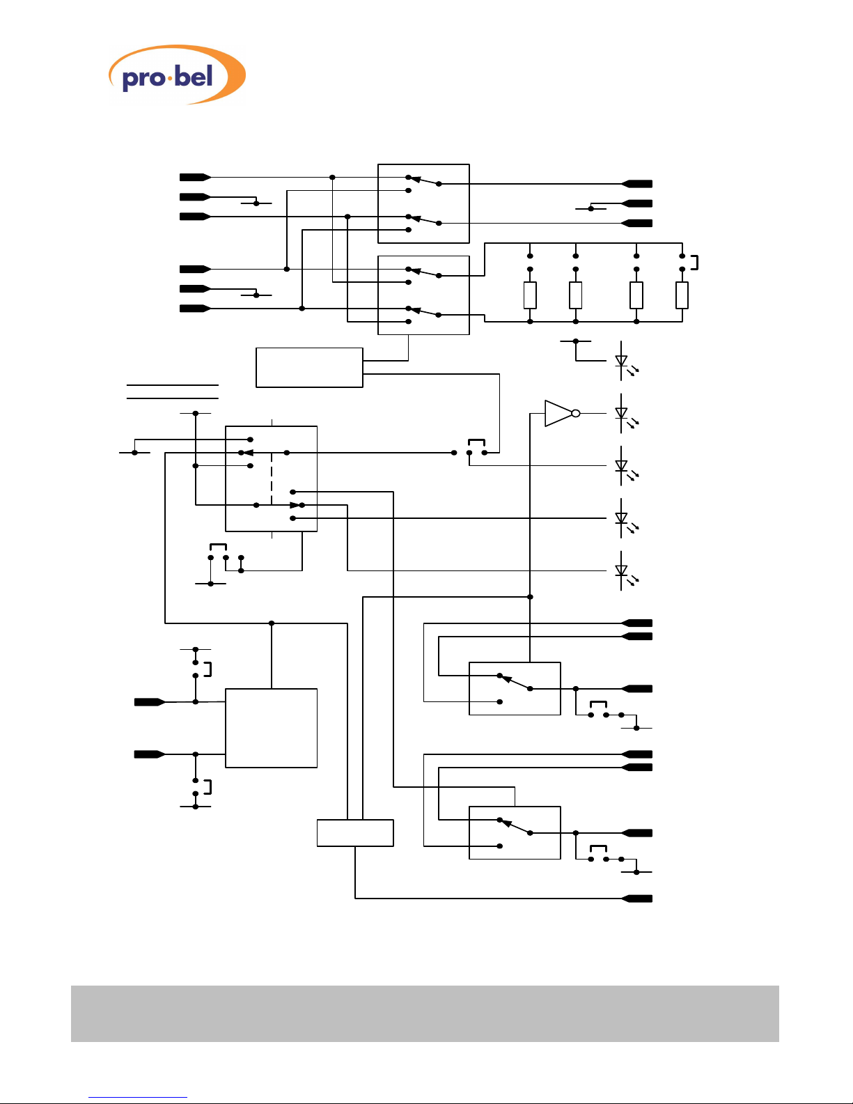
1.1 Functional Block Diagram – ScrewTerminalType (ChannelA)
LOCAL- 1
LOCAL- 2
INPUT 1
INPUT 2
LOCAL
REMOTE
REMOTE
RELAY3
INPUT 2
SELECTED
INPUT 1
SELECTED
COMMON
OPTO-
ISOLATED
CONTROL
INPUT
RELAY4
LOCAL
SELECTED
REMOTE
SELECTED
COMMON
DART
DART IF
CONTROLA
ACTIVE
LO
ACTIVE
HI
FPSWITCH DISABLE
JP1
JP2
+12V
0V
JP3
0V
JP6
JP7
JP5
CONREV
INPUT
A1 OUTPUT
A
50R
RELAY1
+
-
+
-
RELAY2
+
-
INPUT
A2
S
S
S
RELAYCOIL
OPERATEDOK?
POWER
FRONT PANEL
SWITCH(SW1)
0V
0V
75R600R HIZ
JP8JP9JP10JP11
0V
0V
0V

VISTEKV1693dual changeoverswitch
HU-V1693 5
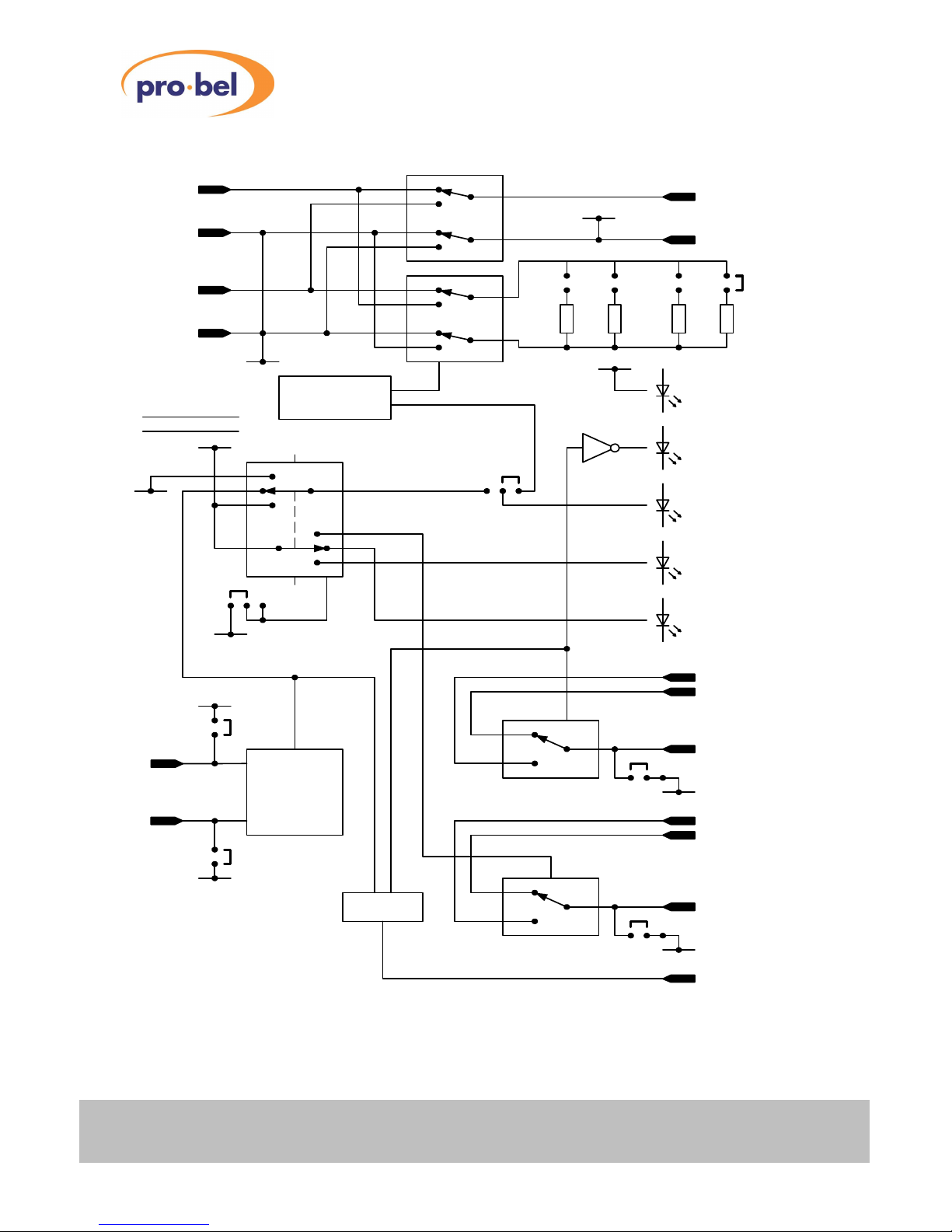
1.2 Functional Block Diagram – ScrewTerminalType (ChannelB)
LOCAL- 1
LOCAL- 2
INPUT1
INPUT2
LOCAL
REMOTE
REMOTE
RELAY7
INPUT2
SELECTED
INPUT1
SELECTED
COMMON
OPTO-
ISOLATED
CONTROL
INPUT
RELAY8
LOCAL
SELECTED
REMOTE
SELECTED
COMMON
DART
DARTIF
CONTROLB
ACTIVE
LO
ACTIVE
HI
FPSWITCHDISABLE
JP14
JP15
+12V
0V
JP16
0V
JP19
JP20
JP18
CONREV
INPUT
B1 OUTPUT
B
50R
RELAY5
+
-
+
-
RELAY6
+
-
INPUT
B2
S
S
S
RELAYCOIL
OPERATED OK?
POWER
FRONT PANEL
SWITCH(SW2)
0V
0V
75R600R HI Z
JP21JP22JP23JP24
0V
0V
0V
VISTEKV1693 dualchangeoverswitch
6Issue 1
1.3 Functional Block Diagram – BNCType (ChannelA)
LOCAL- 1
LOCAL- 2
INPUT1
INPUT2
LOCAL
REMOTE
REMOTE
RELAY3
INPUT2
SELECTED
INPUT1
SELECTED
COMMON
OPTO-
ISOLATED
CONTROL
INPUT
RELAY4
LOCAL
SELECTED
REMOTE
SELECTED
COMMON
DART
DARTIF
CONTROLA
ACTIVE
LO
ACTIVE
HI
FP SWITCHDISABLE
JP1
JP2
+12V
0V
JP3
0V
JP6
JP7
JP5
CONREV
INPUT
A1 OUTPUT
A
50R
RELAY1
RELAY2
INPUT
A2
RELAYCOIL
OPERATED OK?
POWER
FRONT PANEL
SWITCH(SW1)
0V
0V
75R600R HIZ
JP8JP9JP10JP11
0V
0V

VISTEKV1693dual changeoverswitch
HU-V1693 7
1.4 Functional Block Diagram – BNCType (ChannelB)
LOCAL- 1
LOCAL- 2
INPUT 1
INPUT 2
LOCAL
REMOTE
REMOTE
RELAY7
INPUT 2
SELECTED
INPUT 1
SELECTED
COMMON
OPTO-
ISOLATED
CONTROL
INPUT
RELAY8
LOCAL
SELECTED
REMOTE
SELECTED
COMMON
DART
DART IF
CONTROL B
ACTIVE
LO
ACTIVE
HI
FPSWITCH DISABLE
JP14
JP15
+12V
0V
JP16
0V
JP19
JP20
JP18
CONREV
INPUT
B1 OUTPUT
B
50R
RELAY5
RELAY6
INPUT
B2
RELAYCOIL
OPERATEDOK?
POWER
FRONT PANEL
SWITCH (SW2)
0V
0V
75R600R HI Z
JP21JP22JP23JP24
0V
0V

VISTEKV1693 dualchangeoverswitch
8Issue 1
2. INSTALLATION
2.1 Rear Panel Connections
SIGNAL CONNECTOR COMMENTS
A1 3-PIN ST/ BNC Channel A Input 1
A2 3-PIN ST/ BNC Channel A Input 2
A3-PIN ST/ BNC Channel A Output
B1 3-PIN ST/ BNC Channel B Input 1
B2 3-PIN ST/ BNC Channel B Input 2
B3-PIN ST/ BNC Channel B Output
Control & Status26 wayD type See table below
GPI REMOTE
PIN SIGNAL
1Control 0V
2Control +12V
3Control A(Active Low)
4Control A(Active High)
5ARemote Selected
6ALocalSelected
7ARemote/Local Common
8A1/A2 Selected Common
9A1 Selected
10 A2 Selected
11 NC
12 NC
13 NC
14 NC
15 NC
16 NC
17 B2 Selected
18 B1 Selected
19 B2/B1 Selected Common
20 BLocal/Remote Common
21 BLocalSelected
22 BRemote Selected
23 Control B(Active High)
24 Control B(Active Low)
25 Control +12V
26 Control 0V
Important note: Rear module type V16VR3K isnot compatible with module type V1692. See module
datasheetsfor correct types.
Rear Panel Types:V16VR3J V16VR3K

VISTEKV1693dual changeoverswitch
HU-V1693 9
2.2 Hardware Link and Switch Settings
The following table refers to Jumper settings shown in the blockdiagramson pages 4 - 7 at the front of this
userguide. Their physical locations are given on the printed circuit board overlayon Page 10.
Functions of Links etc.
JP1 Insert Linkfor Channel A Active LowControl(JP2 open). Remove both JP1 and
JP2 for an isolated control input.
JP2 Insert Linkfor Channel A Active High Control (JP1 open). Remove both JP1 and
JP2 for an isolated control input.
JP3 Insert Linkin LH position to enable Channel Afront panel input changeovercontrol
switch. Insert in RH position to disable.
JP4 Insert Linkin LH position for Channel Afront panel and external local/remote tallies
to follow Channel A front panel control switch. Insert in RH position forpermanent
remote indication. JP4 is intended to be used in conjunction with JP3.
[Note: JP4 isnot shown in the functional blockdiagrams]
JP5 Insert linkin the position marked REV for the input selection A1/A2 tallies to be
derived fromthe drive to the signal changeoverrelaycoil. Insert linkin the position
marked CON forthe A1/A2 talliesto be derived fromthe front panel or external
control inputs.
JP6 Insert linkin the RH position for the common of the A1/A2 selected tallyto be earth-
free. Insert linkin the LH position for thiscommon to be grounded.
JP7 Insert linkin the RH position for the common of the A remote/A local tallyto be
earth-free. Insert linkin the LH position to ground it.
JP8/JP9/JP10/JP11
Selects Channel A Termination Impedance 50R,75R,600R or Hi Z respectively(Fit
linkto one jumper only).
JP12 Insert Linkfor Remote Switching via GPI port.
JP13 Insert Linkfor Remote Switching overDART.
JP14 Insert Linkfor Channel B Active LowControl(JP15 open).
JP15 Insert Linkfor Channel B Active High Control (JP14 open).
JP16 Insert Linkin LH position to enable Channel Bfront panel input changeovercontrol
switch. Insert in RH position to disable.
JP17 Insert Linkin LH position for Channel Bfront panel and external local/remote tallies
to follow Channel B front panel control switch. Insert in RH position forpermanent
remote indication. JP17 isintended to be used in conjunction with JP16.
[Note: JP17 is not shown in the functional blockdiagrams]
JP18 Insert linkin the position marked REV for the input selection B1/B2 tallies to be
derived fromthe drive to the signal changeoverrelaycoil. Insert linkin the position
marked CON forthe B1/B2 talliesto be derived fromthe front panel or external
control inputs.
JP19 Insert linkin the RH position for the common of the B1/B2 selected tallyto be earth-
free. Insert linkin the LH position to ground it.
JP20 Insert linkin the RH position for the common of the B remote/B local tallyto be
earth-free. Insert linkin the LH position forthiscommon to be grounded.
JP21/JP22/JP23
JP24
Selects Channel B Termination Impedance 50R,75R,600R or Hi Z respectively(Fit
linkto one jumper only).
JP25 Insert Linkfor Remote Switching via GPI port.
JP26 Insert Linkfor Remote Switching overDART.

VISTEKV1693 dualchangeoverswitch
10Issue 1
VISTEKV1693 dualchangeoverswitch
11
3. OPERATION
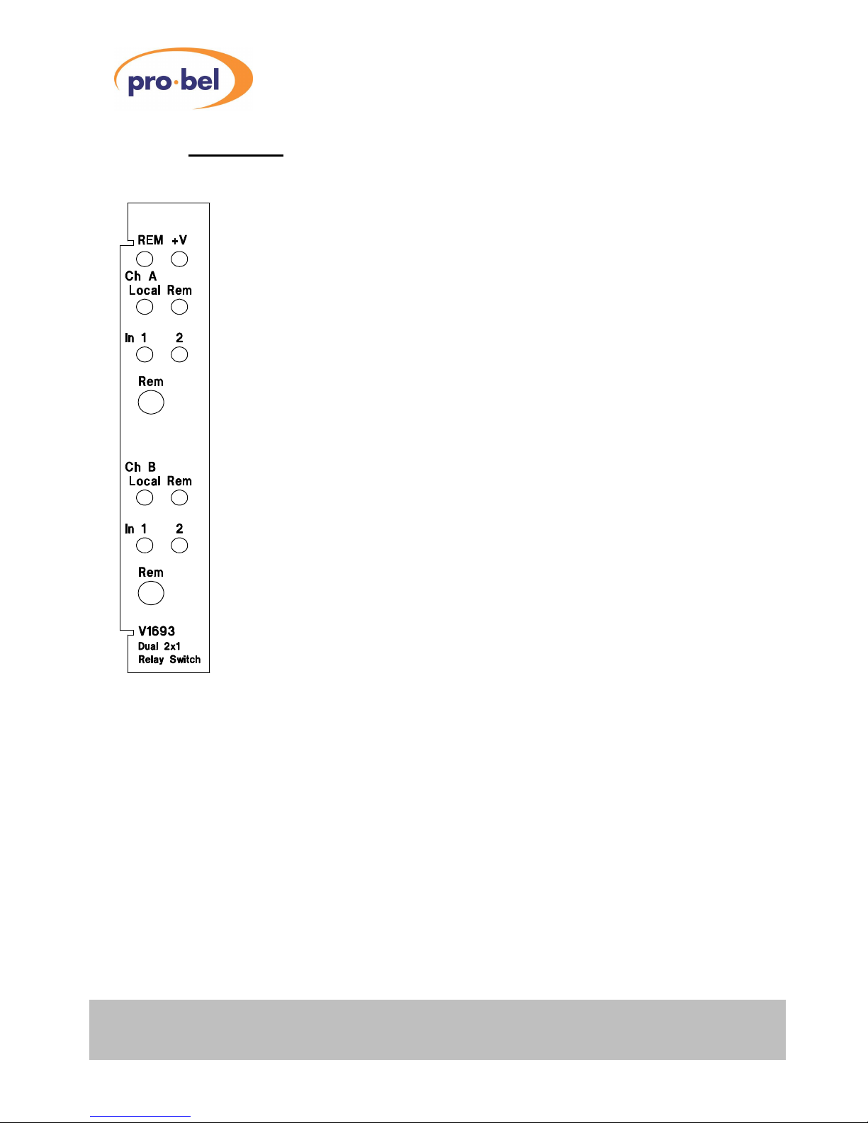
3.1 Front Panel Controls and Indications
LED Indicators:
REM Yellow– Flashing indicates DARTcontrol active
+V Green – Indicates DC power present & OK
Local Red – Input selection controlled fromfront panel
Rem Green – Input selection controlled remotely
In 1 Yellow– Input 1 selected
In 2 Yellow– input 2 selected
Toggle Switches (3 position):
Rem Left: Input 1
Centre: Remote
Right: Input 2

VISTEKV1693 dualchangeoverswitch
12Issue 1
3.2 Configuration
Configuration ofthe V1693 consistsof positioning links JP1 – JP26 to set the following for each channel:
• Remote control input active high/active low/isolated.
• Front panel signal changeovercontrol and associated remote/local indications enabled/disabled.
• Derivation ofinput selection tallies.
• Input selection and local/remote talliesto be grounded common or ground-free.
The functions ofthese links are described in detail in Section 2.2.
3.3 Remote Control
The V1693 has two remote control options:
• Contact closureor 12V (dependent on configuration) applied to the remote control port routesthe output
ofa channel to Input 2. The output isrouted to Input 1 in the absence of a control input.
• Control over DARTnet fromaV1605 orViewfind controller when the unit isfitted into aDART-equipped
V1606 or V1603 rack.
Table of contents
Other pro bel Switch manuals


Popular Switch manuals by other brands


Ascentic
Ascentic MH4 Series user manual

Sony
Sony DFS-700 operating instructions

United Electric Controls
United Electric Controls J21K Installation and maintenance instructions

Siemens
Siemens SIMATIC NET RUGGEDCOM i802 installation manual

Altusen
Altusen KVM Over the NET KN2124v user manual

OEZ
OEZ FH2-1 Series Instructions for use