pro bel 3408 User manual

ontents
1Introduction
2Installation 4
.1Signal I/O and control pinout 5
. Crosspoint control 6
3onfiguration 8
3.1Selecting the signal type 10
3. Setting the local/remote mode 11
3.3Configuring an 8x1 switcher 11
3.4Source expansion 1
3.5Level expansion 14
4Trouble shooting 16
5OSMOS status monitoring 18
6Specification 0
7Ordering Information
Technical Manual 1
3408Serial Digital Video/Telecom 8x1 Switch

1Introduction
he 3408 is an eight input, one output serial digital video/telecom switcher intended
for use with all composite and component serial digital video and telecom signals
between 139 and 360 Mbit/s. he switcher has been designed to fit in either the 1U
1051 or 3U 1050 Pro-Bel modular product rackframes. In the 1050 frame the module
occupies 30mm of rack space. It provides a solution for small ancillary or
monitoring matrices with the benefit of simple button per crosspoint control.
he architecture of the modules allow crosspoint outputs to be bussed together to
allow switchers above eight inputs to be built. In addition, the switcher may be
configured with other modules in the Pro-Bel range to form married multi-level
matrices.
An onboard rechargeable battery provides retention of crosspoint settings after
power loss.
Characteristics of the module are:
•easy expansion up to 64 inputs
•output regeneration (re-clocking)
•flexible control, with button per crosspoint or binary addressing
•black and burst reference input
•wide selection of data rates: serial digital video - 143, 177, 270 and 360Mbit/s,
DVB-ASI @ 270Mbit/s, telecom - 139 (PDH) and 155(SDH)
•crosspoint memory via battery backup
•front mounted crosspoint tally display
•compatible with Pro-Bel COSMOS status monitoring
2 Issue 3
3408

Technical Manual 3
3408Serial Digital Video/Telecom 8x1 Switch
CONTROL
INPUTS AND
LAMP SUPPLY
DC POWER
AND
STATUS DATA
VID / CNTL
EXP IN
VID / CNTL
EXP OUT
ADDRESS
EXP OUT
9x1
8 VIDEO/TELECOM
DIGITAL INPUTS VIDEO/TELECOM
DIGITAL OUTPUTS
ADDRESS
EXP IN
CONTROL
LOGIC
POWER
REG
EXPANSION
CONFIG
BATT
VID EXP INPUT
STATUS
MON
ANALOGUE
REF INPUT
REGEN-
ERATOR
OUTPUT
DRIVER
408 8x1 digital video/telecom switcher
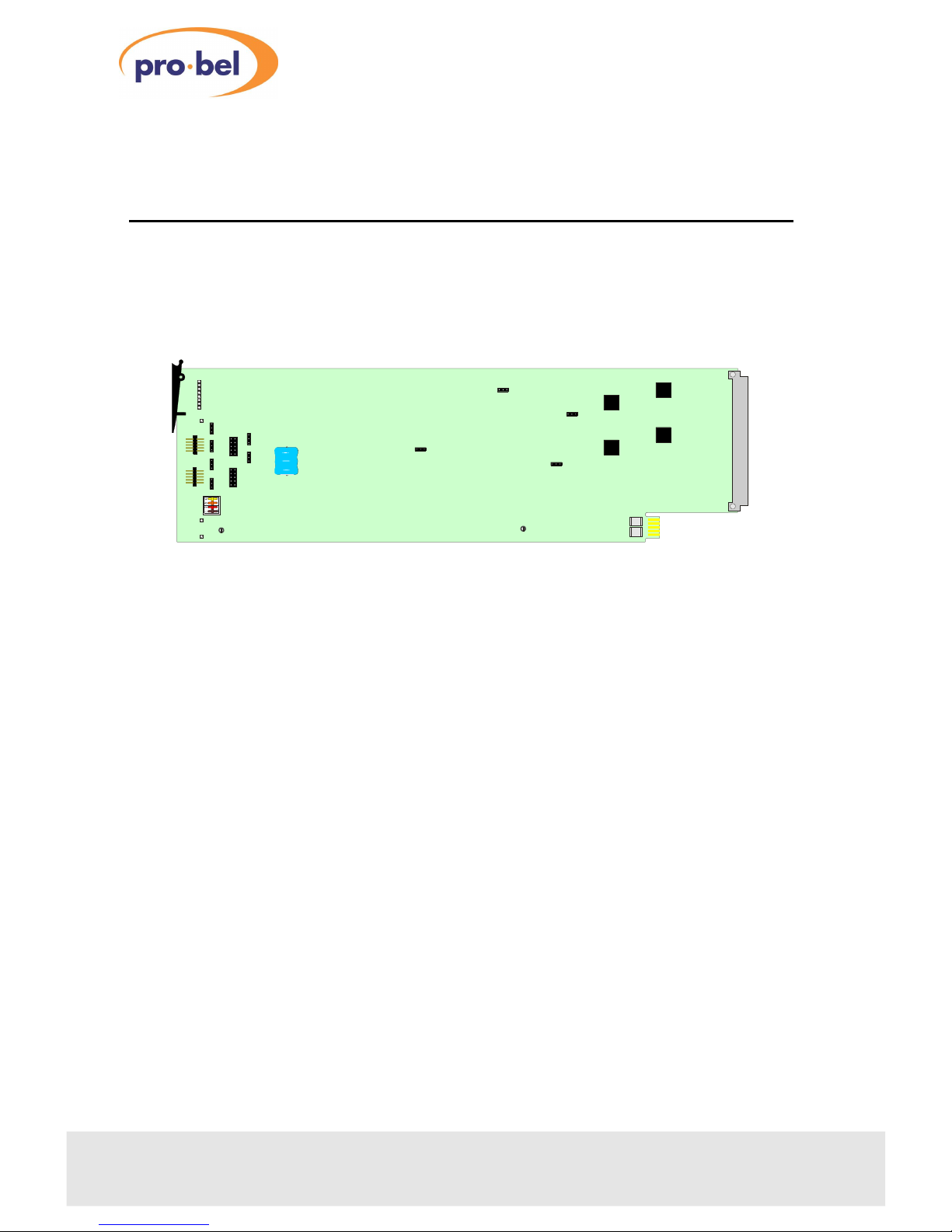
2Installation
he 8x1 digital video/telecom video switcher consists of a 3408 ICON module which
uses the 30mm K3408.3 rear connector. he rear connector occupies 30mm in a 3U
1050 ICON frame and one slot in the 1051 ICON frame.
For module and rear connector installation instructions please refer to the
appropriate ICON rackframe section of this manual.
4 Issue 3
3408
P1 0V P2 0V
POLL
ERROR
POWER
BIN/PL8 BIN
PL9
CON ROL
PL6
I/P
PL7
CON ROL
O/P
OFF
ON
PL14
PL15
OFF
ON
PL16
OFF
ON
OFF
ON
PL10
PL11
OFF
ON
CHAN SEL
PL3
OFF/ON
F LOGIC
PL2
MODE
BU ON/BIN
PL12
PL4
OFF/ON
MODE
ELCO/DVID
3408
1
2
3
4
5
6
7
8
SW1
REMO E
RAE 2
RAE1
RAE0
BAERY
RSF1
RSF2
REMO E
OFF
ON
PL13
The 408 8x1 digital video switcher

2.1Signal I/O and control pinout
he K3408.3 rear connector has ten BNC connections for signal I/O and one 15 way
‘D’ type socket for control
Technical Manual 5
3408Serial Digital Video/Telecom 8x1 Switch
BN input/output
connectors
BNCFunction
1I/P 1
I/P 2
3I/P
4I/P 4
5I/P 5
6I/P 6
7I/P 7
8I/P 8
9ANALOGUE REFERENCE
10 DIGITAL OUTPUT
ontrol Pin outs
PinFunctionPinFunction
1SEL 1 9A2EXT
SEL 2 10 A1EXT
3SEL 11 A0EXT
4SEL 4 1 A EXT
5SEL 5 13 LAMPSUP
6SEL 6 14 OV
7SEL 7 15 SCREEN
8SEL 8
K3408.3
SDI
INPU S
CON ROL
1
3
5
7
2
4
6
8
VID REF
OU

2.2rosspoint control
onnecting button panels
Crosspoints may be selected by connecting a button panel (eg. Pro-Bel’s 8 button
6200 or 16 button 6202) to the control socket on the K3048.3 rear panel and setting
PL2 to ‘Button’ . Alternatively, custom button panels can be built using the following
wiring diagram.
he 3408 switcher has priority switching built in. If two keys are pressed
simultaneously, the higher numbered one will be selected. his feature allows ‘line
up’ to be performed quickly. o achieve this, one key must be held down and a
higher numbered key pushed and released. Each time the higher numbered key is
pushed and released that source will be selected, as long as the button is held down.
Once the button is released, the previous source is selected again.
wo 8x1 modules may be independently controlled from a 16 button panel, such as
the Pro-Bel 6202. his particular panel has two separate connectors to plug into the
control socket on each module, simplifying the installation. If the internal expansion
cables are fitted (see Source expansion), priority switching can be performed across
several modules. he highest priority module will always be the leftmost, viewed
from the front of the cards.
Using binary control
o use binary control instead of a button panel, PL2 must be set to ‘BIN’. Crosspoints
may be selected by binary addressing according to the table below, using 12V CMOS
levels using the Control socket on the rear connector.
6 Issue 3
3408
SEL 1 SEL SEL 3 SEL 4 SEL 5 SEL 6 SEL 7 SEL 8OV LAMPSUP GND
Example 8 way button panel wiring diagram

*Crosspoint output is tri-stated - used for system expansion.
LOGIC 1 = +12V, LOGIC 0 = 0V
Binary control signals can be generated by one 8x1 module and fed to another, to
create a master slave configuration. o achieve this, the lower expansion cable on
the front of the cards must be fitted, and all slave modules set to binary mode. he
master module can be set to button mode and conveniently driven from a button
panel.
Technical Manual 7
3408Serial Digital Video/Telecom 8x1 Switch
Binary addressing
I/PA EXTA1 EXTA0 EXTA3EXT
10000
0010
30100
40110
51000
61010
71100
81110
*XXX1

3onfiguration
he module is easy to configure and build into expanded systems using
configuration jumpers.
8 Issue 3
3408
onfiguration jumpers
JumperConditionFunction
PL BUTTON
BIN
Simple button per crosspoint control
Binary control, used in expanding systems and computer control
PL3 OFF or ONInternal field trigger, FTLOGIC connection
PL10 &PL11 OFF or ONDigital video signal expansion bus, used when expanding sources
PL4 OFF or ONTelco/Video mode select
PL1 OFF or ONExpansion input enable
PL13 OFF or ONDISOUT, used to disable downstream cards when expanding sources
PL14 OFF or ONCLKI/O, output clock for downstream cards when expanding sources
PL15 OFF or ON FTLEXT, external FTLOGIC connection, used to distribute the field
trigger to downstream cards for synchronous switching
PL16 OFF or ON Common battery supply line, used to distribute .6V crosspoint
retention power to other boards in a system
PL6
PL7
PL9
REGEN-
ERATOR
VID EXP IN
CONTROL PANEL AND
BINARY SELECT LINES
LAMP SUPPLY
ANALOGUE REF
INPUT
LOW VOLTAGE
DC SUPPLY
EXP VID+
PL10
EXP VID-
P11
DIS OUT
PL13
CLOCK I/O
PL14
FLD TRIG
PL15
BATT SUP
PL16
9x1
8 VIDEO/TELECOM
DIGITAL INPUTS
MODE
BUTTON/BIN
PL2
PL4
MODE
TEL O/VID
PL3
PL12
EXP
HANNEL SELET LEDS
H 1
H 2
H 3
H 4
H 5
H 6
H 7
H 8
POWER LED
+1 V
VIDEO /TELECOM
DIGITAL OUTPUT
PL8
CONTROL
LOGIC
POWER
REG
EXPANSION
ENABLE
JUMPERS
BATT
STATUS DATA
STATUS
MON
+5V
-5V
- V
RSF1
RSF
RSF3
SW1
BIT RATE
/REMOTE
SYN SEP
ON/OFF
OUTPUT
DRIVER

he physical location of these jumpers is indicated below.
Technical Manual 9
3408Serial Digital Video/Telecom 8x1 Switch
Configuration jumper locations
P2 0V
PL3
OFF/ON
F LOGIC
PL12
PL4
OFF/ON
MODE
ELCO/DVID
RSF1
RSF2
P1 0V
POLL
ERROR
POWER
BIN/PL8 BIN
PL9
CONROL
PL6
I/P
PL7
CONROL
O/P
OFF
ON
PL14
PL15
OFF
ON
PL16
OFF
ON
OFF
ON
PL10
PL11
OFF
ON
CHAN SEL
PL2
MODE
BU ON/BIN
3408
1
2
3
4
5
6
7
8
SW1
REMO E
RAE 2
RAE1
RAE0
BAERY
REMOE
OFF
ON
PL13
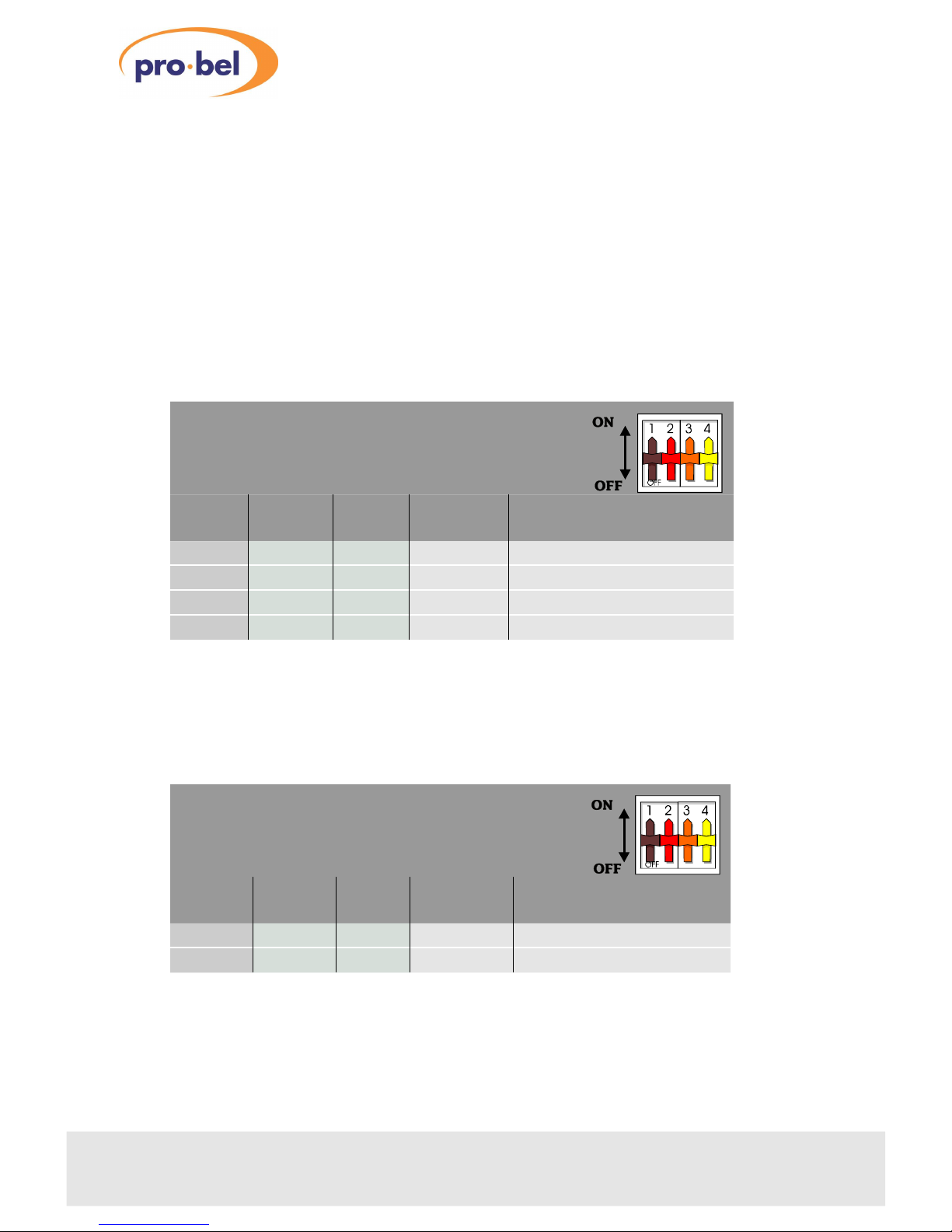
3.1Selecting the signal type
o use the switcher in either telecom or serial digital video mode the correct data
rate and O/P level must be selected.
he operating mode is selected by setting jumper PL4 and switch SW1 on the card.
Serial digital video and DVB-ASI modes
PL4 must be set to ‘DVID’ and switch SW1 is set according to the following data rate
table:
Telecom mode
PL4 must be set to ’ ELCO’ and switch SW1 is set according to the following data rate
table:
10 Issue 3
3408
Data rate in SDI and DVB-ASI mode
1=ON, 0=OFF
RATE 0
SW1-1
RATE 1
SW1-
RATE
SW1-3
Data rate
Mbit/s Mode
001
60Component EDTV
101
270Component 625/525
011
177Composite 625
111
14 Composite 525
Data rate in Telco mode
1=ON, 0=OFF
RATE 0
SW1-1
RATE 1
SW1-
RATE
SW1-3
Data rate
Mbit/s Mode
110
1 9.264PDH
010
155.520SDH
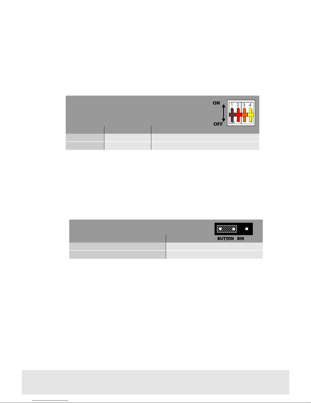
3.2Setting the local/remote mode
he control of data rate selection can be transferred to the COSMOS status
monitoring system with SW1-4.
he yellow remote LED will illuminate when the remote mode is selected.
3.3onfiguring an 8x1 switcher
he method of crosspoint selection is set by PL2.
Configuration changes are accomplished by pulling the jumper (the shaded area
above) from its current position on the header pin block and moving it to the
alternate position on the same block. Normally, the jumper should make contact
with two pins
Technical Manual 11
3408Serial Digital Video/Telecom 8x1 Switch
Assigning data rate control
1=ON, 0=OFF
SW1-4Control modeNotes
0LocalUse SW1, 1- for data rate
1RemoteCOSMOS controls data rate, local control disabled
PL2 rosspoint control
PositionFunction
BUTTON Crosspoint selection using a button panel
BIN Crosspoint selection using binary control
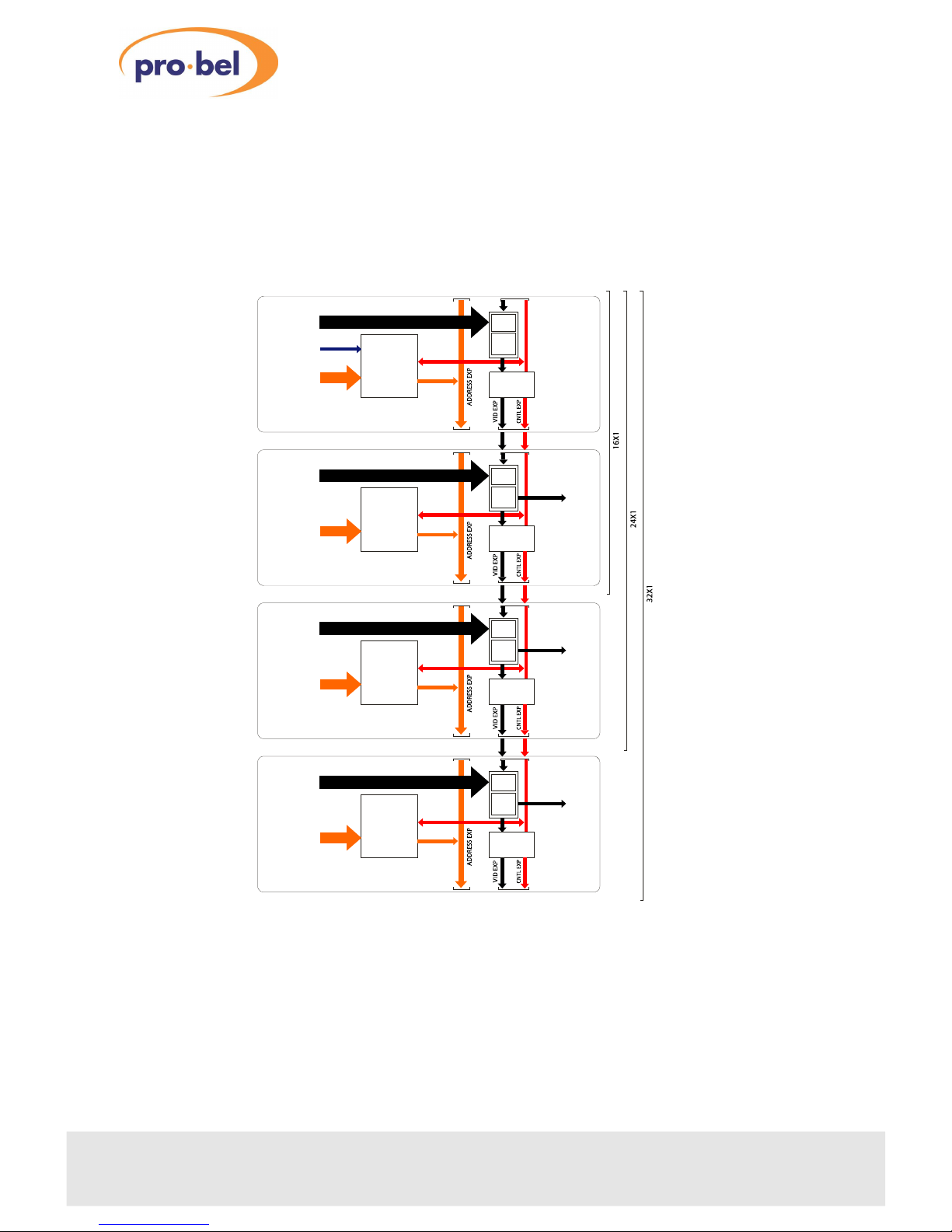
3.4Source expansion
Several 3408 cards can be linked to make larger switchers up to 64x1. Expansion
employs the front of card connectors together with the ribbon cable supplied with
the card. he output is always taken from the last downstream card.
Expansion to 40, 48, 56 and 64 x1 simply requires further modules added to the
expansion chain using the ribbon cables provided.
12 Issue 3
3408
CONTROL
INPUTS 1-8
PL7
9x1
DIGITAL
INPUTS 1-8
CONTROL
LOGIC EXPANSION
CONFIG
ANALOGUE
REF INPUT
PL9
PL6PL8
PL1 OFF
PL10,11 ON
REGEN/
LINE
DRIVER
PL3 ON
PL13,14,15 ON
PL BUTTON
PL16 OFF
CONTROL
INPUTS 9-16
PL7
9x1
DIGITAL
INPUTS 9-16
CONTROL
LOGIC EXPANSION
CONFIG
PL9
PL6PL8
PL1 ON
PL10,11 ON
REGEN/
LINE
DRIVER
PL3 OFF
PL13,14,15 ON
PL BUTTON
PL16 OFF
CONTROL
INPUTS 17- 4
PL7
9x1
DIGITAL
INPUTS 17- 4
CONTROL
LOGIC EXPANSION
CONFIG
PL9
PL6PL8
PL1 ON
PL10,11 ON
REGEN/
LINE
DRIVER
PL3 OFF
PL13,14,15 ON
PL BUTTON
PL16 OFF
CONTROL
INPUTS 5-3
PL7
9x1
DIGITAL
INPUTS 5-3
DIGITAL OUTPUT
CONTROL
LOGIC EXPANSION
CONFIG
PL9
PL6PL8
PL1 ON
PL10,11 ON
REGEN/
LINE
DRIVER
PL3 OFF
PL13,14,15 ON
PL BUTTON
PL16 OFF
DIGITAL OUTPUT
DIGITAL OUTPUT
FOR 16X1 EXP
FOR 4X1 EXP
FOR 3 X1 EXP
Expanding to 16,24 and 2 x 1

he following rules apply to source expansion from 16x1 to 64x1 under button
control:
•only video/control expansion bus used
•each card requires unique eight button control
•expansion output taken from last card in chain
•sync separator field trigger enabled on first card in chain
•synchronous switching between video sources is only possible if all sources are
already synchronised to one reference
Technical Manual 13
3408Serial Digital Video/Telecom 8x1 Switch
Source expansion to 64x1 with 8 modules
VID/CN L EXPANSION
VER SYNC
PL7
BEHIND
PL6
PL6
PL7
BEHIND
PL6
PL6
PL7
BEHIND
PL6
PL7
BEHIND
PL6
PL7
BEHIND
PL6
PL7
BEHIND
PL6
PL7
BEHIND
PL6
PL7
BEHIND
PL6
PL6PL6PL6PL6PL6PL6
PL8PL8PL8PL8PL8PL8PL8PL8
Synchronous source expansion with button panel control
JumperCard 1Card -8Function
PL BUTTONBUTTONControl mode
PL3 ONOFFInternal FTLOGIC connection
PL10 &PL11 ONONDigital video signal expansion O/P
PL1 OFFONExpansion input enable
PL13 ONONDISOUT, priority switching signal
PL14 ONONCLKI/O, module selector signal
PL15 ONONFTLEXT, external FTLOGIC connection
PL16 OFFOFFCommon battery supply line
Note: Set PL3 and PL15 to OFF for asynchronous switching (crash mode)

3.5Level expansion
It may be useful in some applications for one card to control the input selection of
other cards to create a multi-level switcher. his mode is called master/slave and
utilises the binary address interconnections.
he master card can be driven from a button panel and all the other cards by binary
addressing using only the lower expansion connectors PL8-PL9 on the front of the
card.
In this example of a synchronous three level audio switcher, both address and
control/video expansion bus connectors are used. It may be desirable to distribute a
vertical trigger signal from the first card (leftmost) in the expansion to ensure
switching during the correct line of a reference video field. his is why the vid/cntl
ribbon is used. However, the video expansion jumpers 10 and 11 must be OFF on all
cards.
14 Issue 3
3408
Level expansion with synchronous switching
CONTROL
INPUTS 1-8
PL7
9x1
INPUTS
1-8 LEVEL 1
CONTROL
LOGIC EXPANSION
CONFIG
ANALOGUE
REF INPUT
PL9
PL6PL8
PL1 OFF
PL10,11 OFF
REGEN/
LINE
DRIVER
PL3 ON
PL15 ON
PL BUTTON
PL13,14,16 OFF
PL7
9x1
INPUTS
1-8 LEVEL
CONTROL
LOGIC EXPANSION
CONFIG
PL9
PL6PL8
PL1 OFF
PL10,11 OFF
REGEN/
LINE
DRIVER
PL3 OFF
PL15 ON
PL BUTTON
PL13,14,16 OFF
PL7
9x1
INPUTS
1-8 LEVEL 3
CONTROL
LOGIC EXPANSION
CONFIG
PL9
PL6PL8
PL1 OFF
PL10,11 OFF
REGEN/
LINE
DRIVER
PL3 OFF
PL15 ON
PL BUTTON
PL13,14,16 OFF
DIGITAL OUTPUT
DIGITAL OUTPUT
FOR LEVEL
FOR LEVEL 3
DIGITAL OUTPUT
FOR LEVEL 1

he following rules apply to synchronous level expansion
•address and video/control expansion buses used
•outputs taken from each card for each level
•maximum of four levels can be controlled
•levels may include mixed signal formats
•sync separator field trigger enabled on first card in chain
•synchronous switching between video sources is only possible if all sources are
already synchronised to one reference
Technical Manual 15
3408Serial Digital Video/Telecom 8x1 Switch
level expansion with synchronous switching
Jumper Card 1Card -3Function
PL BUTTONBINControl mode
PL3 ONOFFInternal FTLOGIC connection
PL10 & PL11 OFFOFFDigital video signal expansion O/P
PL1 OFFOFFExpansion input enable
PL13 OFFOFFDISOUT, priority switching signal
PL14 OFFOFFCLKI/O, module selector signal
PL15 ONONFTLEXT, external FTLOGIC connection
PL16 OFFOFFCommon battery supply
Level expansion to three level switcher with three modules
VID/CN L EXPANSION
VER SYNC
PL7
BEHIND
PL6
PL9
BEHIND
PL8
PL6
PL8
ADDRESS EXPANSION
PL7
BEHIND
PL6
PL6
PL7
BEHIND
PL6
PL6
PL9
BEHIND
PL8
PL8 PL9
BEHIND
PL8
PL8
Note: Set PL3 and PL15 to OFF and PL 14 ON on all cards for asynchronous
switching (crash mode)

4Trouble shooting
The green card edge POWER LED is not lit
•check the PSU indicator to confirm that there is power to the frame
•if necessary examine the fusible resistors RSF1, RSF2 protecting the card to see if
they have operated - turn the power off and wait for 30 seconds before restoring
the power
•if necessary, refer to the power supply trouble shooting guide in the appropriate
ICON rackframe manual section
There is no output signal
•ensure that the green card edge POWER LED is lit
•check that the inputs are connected to the rear panel and a valid signal is present
•verify that the correct channel is selected - the LED on the button panel should
show the same channel as the CHAN SEL LED on the front of the module
•check the output connection from the rear panel to the monitoring device and
the output cable
•ensure that the cable wiring and jumper link settings are correct for the
configuration used
The button panel will not select a different input
•ensure that the jumper PL2 is correctly set to ‘BU ON’ on all modules
•check that the expansion cables are correctly installed
•check that another, higher numbered, input is not permanently selected
The red error LED is lit (regenerator unlocked)
•check that SW1 and PL4 are set to the correct signal type and bit-rate
The output signal is corrupted
•check that the red error LED is not lit
•ensure all expansion cables are installed correctly
16 Issue 3
3408

Technical Manual 17
3408Serial Digital Video/Telecom 8x1 Switch

5OSMOS status monitoring
If the frame is equipped with a COSMOS controller card the following parameters will
be reported back to the COSMOS status monitoring system.
•module present
•input selected
•data rate selected
•remote/local mode
•module power LED status
he following module parameters may be controlled through the status monitoring
system when remote operation is enabled:
•data rate selection
In addition, the module is programmed with the following information, which can be
read by the status monitoring controller:
•module type
•module bar code
•module issue no
For further details of the Pro-Bel status monitoring system please refer to the
COSMOS status monitoring manual.
18 Issue 3
3408

Technical Manual 19
3408Serial Digital Video/Telecom 8x1 Switch

6Specification
Inputs
Number and type: 8, 75W 270Mbit/s serial data to SMP E 259M-ABCD
Return loss: ³15dB, 7 to 360MHz
covers G703-9, G703-12 and SMP E259M
Maximum cable length:50m @ 270Mbit/s
25m @ 360Mbit/s
100m @ 177Mbit/s and 143Mbit/s
100m @ 155Mbit/s and 139Mbit/s
Reference input
Number and type: 1, 75W composite video or black and burst
Outputs
Number and type: 1, 75W serial data to SMP E 259M-ABCD
Return loss:>20dB, 7 to 360MHz
Output level: 800mV±80mV (serial digital video)
1V±100mV (telecom)
elecom outputs to G703-9 and G703-12
(139Mbit/s and 155Mbit/s)
Over/undershoot: < ± 5%
Rise/fall time:Nominally <600ps difference between rise/fall
times <100ps
DC offset: < ± 0.5V
Indications
Power:Green LED
Input selected:8 x yellow LEDs
Error:Red LED
Remote:Yellow LED
20 Issue 3
3408
This manual suits for next models
1
Table of contents
Other pro bel Switch manuals


Popular Switch manuals by other brands

INVERTO.TV
INVERTO.TV Unicable IDLP-UST111-CU010-8PP installation manual

SBC
SBC Q.NET-5TX user manual

PowerDsine
PowerDsine PD-3006 user guide

Cisco
Cisco 6500 - Catalyst Series 10 Gigabit EN Interface Module... user manual

Panasonic
Panasonic GA-AS10T Series installation guide

Raritan
Raritan DOMINION KSX II Quick setup guide


Matrix Switch Corporation
Matrix Switch Corporation MSC-2HD1624L product manual

Luxul
Luxul XFS-1084P Quick install guide

Dell
Dell PowerConnect 2016 user guide

ADTRAN
ADTRAN TRDDS-R Installation and Maintenance

Siemens
Siemens S3VA52T installation instructions

Extron electronics
Extron electronics SW2 VGArs user manual