manuals.online logo
Brands
  1. Home
  2. •
  3. Brands
  4. •
  5. Pro-Form
  6. •
  7. Treadmill
  8. •
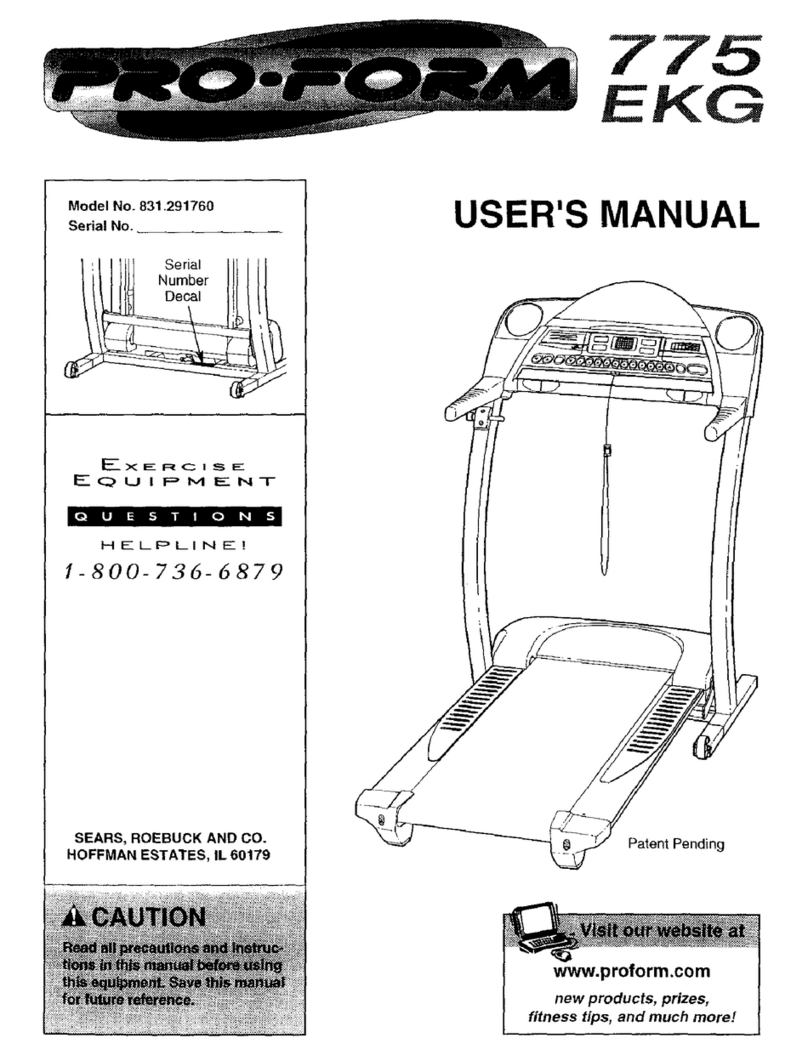
  9. Pro-Form EKG 831.297880 User manual

Pro-Form EKG 831.297880 User manual

Other Pro-Form Treadmill manuals

Pro-Form ZT6 User manual

Pro-Form

Pro-Form ZT6 User manual

Pro-Form DRTL39220 User manual

Pro-Form

Pro-Form DRTL39220 User manual

Pro-Form CROSSWALK 495CW User manual

Pro-Form

Pro-Form CROSSWALK 495CW User manual

Pro-Form 620 V Treadmill User guide

Pro-Form

Pro-Form 620 V Treadmill User guide

Pro-Form 535LE User manual

Pro-Form

Pro-Form 535LE User manual

Pro-Form 3.9 Xm Treadmill User manual

Pro-Form

Pro-Form 3.9 Xm Treadmill User manual

Pro-Form DTL12940 User manual

Pro-Form

Pro-Form DTL12940 User manual

Pro-Form 580 LT User manual

Pro-Form

Pro-Form 580 LT User manual

Pro-Form PFTL10042 User manual

Pro-Form

Pro-Form PFTL10042 User manual

Pro-Form XP Trainer 580 User manual

Pro-Form

Pro-Form XP Trainer 580 User manual

Pro-Form 730 Zlt Treadmill Quick start guide

Pro-Form

Pro-Form 730 Zlt Treadmill Quick start guide

Pro-Form 690 Vx Treadmill System manual

Pro-Form

Pro-Form 690 Vx Treadmill System manual

Pro-Form PFTL611040 User manual

Pro-Form

Pro-Form PFTL611040 User manual

Pro-Form 765x Treadmill User manual

Pro-Form

Pro-Form 765x Treadmill User manual

Pro-Form 3.6 Treadmill User manual

Pro-Form

Pro-Form 3.6 Treadmill User manual

Pro-Form 831.297361 User manual

Pro-Form

Pro-Form 831.297361 User manual

Pro-Form 690 Vx Treadmill Quick start guide

Pro-Form

Pro-Form 690 Vx Treadmill Quick start guide

Pro-Form PFTL59291 User manual

Pro-Form

Pro-Form PFTL59291 User manual

Pro-Form 760 EKG 831.291670 User manual

Pro-Form

Pro-Form 760 EKG 831.291670 User manual

Pro-Form T10.0 PFTL05051 User manual

Pro-Form

Pro-Form T10.0 PFTL05051 User manual

Pro-Form 1210 RT User manual

Pro-Form

Pro-Form 1210 RT User manual

Pro-Form 585 Perspective Treadmill System manual

Pro-Form

Pro-Form 585 Perspective Treadmill System manual

Pro-Form 590QS 831.299243 User manual

Pro-Form

Pro-Form 590QS 831.299243 User manual

Pro-Form 560 Cross Trainer Treadmill User manual

Pro-Form

Pro-Form 560 Cross Trainer Treadmill User manual

Popular Treadmill manuals by other brands

Motus M990T Service manual

Motus

Motus M990T Service manual

NordicTrack APEX4100i NTTL18906 user manual

NordicTrack

NordicTrack APEX4100i NTTL18906 user manual

CAPITAL SPORTS Pacemaker Touch manual

CAPITAL SPORTS

CAPITAL SPORTS Pacemaker Touch manual

Insportline Hill Pro user manual

Insportline

Insportline Hill Pro user manual

Expondo Gymrex GR-MG31 user manual

Expondo

Expondo Gymrex GR-MG31 user manual

HEALTH ONE Walk Ro user manual

HEALTH ONE

HEALTH ONE Walk Ro user manual

NordicTrack T7.5 S user manual

NordicTrack

NordicTrack T7.5 S user manual

Gold's Gym ADVANTAGE GGTL12920 user manual

Gold's Gym

Gold's Gym ADVANTAGE GGTL12920 user manual

Merax MS282992 manual

Merax

Merax MS282992 manual

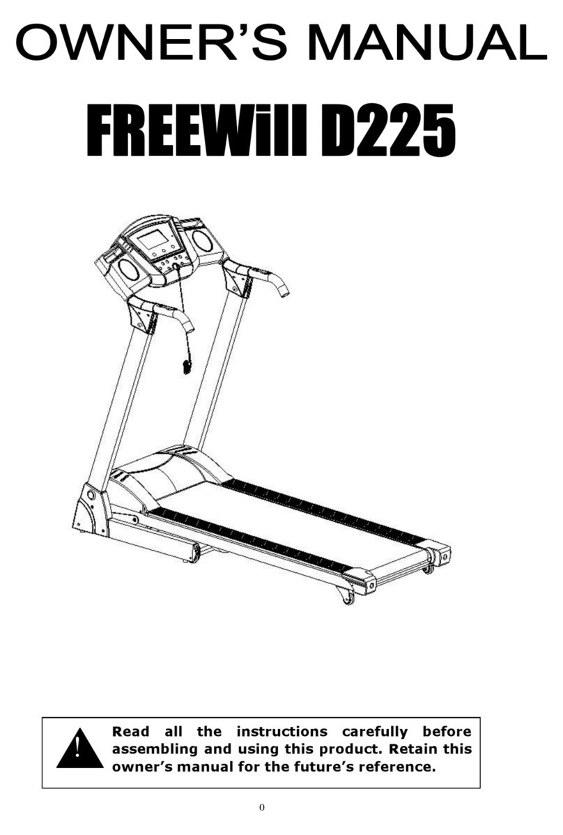
FitLogic freewill d225 owner's manual

FitLogic

FitLogic freewill d225 owner's manual

HOP-SPORT ESTIMA HS-3200LB instruction manual

HOP-SPORT

HOP-SPORT ESTIMA HS-3200LB instruction manual

Stamia InMotion II owner's manual

Stamia

Stamia InMotion II owner's manual

Smooth Fitness EVO 3i user manual

Smooth Fitness

Smooth Fitness EVO 3i user manual

NordicTrack NETL81810.0 user manual

NordicTrack

NordicTrack NETL81810.0 user manual

Schwinn 830/Journey 8.0 Assembly manual / owner's manual

Schwinn

Schwinn 830/Journey 8.0 Assembly manual / owner's manual

Keys Fitness HealthTrainer HT-740T owner's manual

Keys Fitness

Keys Fitness HealthTrainer HT-740T owner's manual

Spirit XT8 Service manual

Spirit

Spirit XT8 Service manual

NordicTrack T 14.0 Treadmill Manuel de l'utilisateur

NordicTrack

NordicTrack T 14.0 Treadmill Manuel de l'utilisateur

manuals.online logo
manuals.online logoBrands
  • About & Mission
  • Contact us
  • Privacy Policy
  • Terms and Conditions

Copyright 2025 Manuals.Online. All Rights Reserved.

iI
Mo_el No. 831.297880
Seri'al No. J
The ser_ number is-found i_ location
shownbeW_ef_*_W_e_.tmf_,lnumberin
the space above-_i'_future reference.
Serial Number
Decal
_-'X==-i=_;:_ i S==-
.F__Q u n-P M-E:N-r"
,,. • .
HEL_P LI NE1
I800-736-6879
°
.., ...
USER'S MANUAL
SEARS, ROEBUCK AND CO., HOFFMAN ESTATES, IL 60179
TABLE OF CONTENTS
IMPORTANT PRECAUTIONS .............. ................................................... ,,
BEFORE YOU BEGIN ............. "........................................................... 4
ASSEMBLY .......................................................... _"...................
OPERATION AND ADJUSTMENT ............................................................. 6
HOW TO FOLD AND MOVE THE TREADMILL .................................................. 12
MAINTENANCE AND TROUBLE-SHOOTING ................................................... 14
CONDITIONING GUIDELINES ............................................................... 16
NOTES . __,=_ : .. . :____.. _........................ ......................................... 18
ORDERING REPLACEMENT PARTS ......... : ...................................... -...Back Cover
FULL 90"J3AY:..WARR_; .................................... ........... Back Cover
Note: An EXPLODED DRAW!NG and PARTLIST are attached inthe center of this-manual., Please save them for
future reference.
IMPORTANT PRECAUTIONS
2
: _::_'_Jtwl_i|e t_e powerii! _ ...19_Do not attempt to
t_etreadmill :_ .......:_ treadmi!_!until _ ......
The decal shown at the right has been
placed on your treadmill, if the decal is
missing, or if it is not legible, please
call our toll-free HELPLINE to order a
free replacement decal (see the back
cover Of this manual). Apply the decal
in the location shown.
BEFORE YOU BEGIN
Congratulations for purchasing the new PROFORM*
EKG treadmill. The PROFORM EKG treadmill com-
bines advanced technology with innovative design to
let you enjoy an excellent form ofcardiovascular exer-
cise in the convenience and privacy of your home. And
When you're not exercising, the unique PROFORM
EKG can be folded up, requiring less than half theflo0r
space of other treadmills. "..
For your benefit, read this manual carefully before
using the treadmill. If you have additional questions,
please call our toll-free HELPLINE at 1-800-736-6879,
.•
Monday through Saturday, 7a.m. until7 p.m. Central
Time (excluding holidays). Tq help us assist you,
please note the product model number and serial nut
ber before calling;The model number of the treadmill
is 831 •297880• The serial number can be found on a
decal attached to the treadmill (see the front cover of
this manual for the location).
Before reading further, please review the drawing
below and familiarizeyourself with the parts that are
labeled.
Towel Console
Accessory Tray
Pulse Sensor
Water Bottle
(Bottle
not included)
Foot Rails
Handrail
-Storage Latch.
LEFT SIDE
Walking
Handrail
..
RIGHT SIDE
Hood
On/Off
Switch
.Circuit
Breaker
i • "rCord
Front Wheel
Rear Roller
Adjustment Bolts Incline
Leg Cushioned Walking
Platform
4._
ASSEMBLY
..•
Assembly requires two people. Set the treadmill in a cleared area and remc>veall packing materials. Do not
dispose of the packing materials until assembly is completed. Refer to the drawings below .t.oidentify the small
the included• allen wrench¢h_ and your own i_hillips screw-
parts used in assembly. Assembly requires ,and scissors _.
driver ,,==_=E:_), adjustable wrench _ _.. ._ .
Handrail Washer (16)-4
1/2" Screw (13)-2. -
.... "Extension Leg Screw (34)-2
n© @"
_\ Handrai! B°RL._(15 3/4" Screw (91)-4
h
Flange Nut (57)-2
3/8" Washer (61)-2
3 1/2" Handrail Bolt (89)-2
.W'dhthe help of a second person, carefully lay the
treadmill on its right side as shown (refer to the drawing
on page 4to identify the right side).
Insert the Extension Legs (41) into the treadmill. Make
sure that the Extension Legs are turned so the Base
Pads (36) are on the indicated side. Attach each
Extension Leg with an Extension Leg Screw (34).
With the help ofa second person, carefully raise the
treadmill to the upright position so the Extension Legs
(41) are resting flat on the floor.
1
..°
oRefer to HOW TO LOWER THE TREADMILL FOR USE
on page 13. Follow the instructions to lower the treadmill.
Position the Left Handrail (2) on the left Upright (14). The
lower end of the Left Handrail should be on the Outsideof
the Extension Leg (41) as shown. Thread a Handrail Bolt
(15) with a HandrailWasher (16) into the left Upright and
the Left Handrail. Do not.tighten the Handrail Bolt yet.
Attach the lower endof the Left Handrail (2) to the
Extension Leg (41) with a 3 1/2"Handrail Bolt (89), a 3/8"
Washer (61), and a.Flange Nut (57). Do not tighten the
Handrai!_.BoltyeL
2
5
6
.With the help of a second person, hold the Console Base
(6) and the Right Handrail (32) near the right Upright (14)
as shown. Route the Console Wire Hamess (92) through
the bracket on the Right Handrail.
Refer to the inset drawing. Slide the Strain Relief Clip
(88) onto the Console Wire Harness (92). Make sure that;
there isno slack in the Console Wire Harness between
the Strain Relief Clip and the Console Base (6). Insert a
3/4" ,Screw (91) into the-Strain Re]ief Clil__r_d in|o ti_$'i_. ---
dicated hole in the Right.Handrail (32). Tighten the Screw
into the Console Base.
.°
oWith the help of a second person, hold the.Pulse
Handrail (99) near the right Upright (14) as shown. Route
the 30" and 9" Pulse Wii'_s (97, 95) through the bracket
on the Right Handrail (32).
Connect the Console Wire Hamess (92) tothe Upright
Wire Hamess (96). Connect the 30" and 9" Pulse Wires
(97,95) to the Upright Wire Harness (92). Makesure that
the wires with tags are connected to each other. Refer to
the inset drawing if needed.
Insert all wires into the right Upright (14). Insertlhe
bracket on the Right Handrail (32) into theright Upright
(14). Make sure that the wires are not pinched.
5. Attach the Pulse Handra_ (99) to the Left and Right
Handrails (2, 32) with tw.oPulse Handrail Bolts(98) and
Handrail Washers (16).
6. Attach the ConsOle Base (6) to the Left and Right
Handrails (2, 32) with three 3/4" Screws (91).
Bracket_
4
L'-91
__.92_"91
Bracket
99
4"
5
98
=/
32 1-llIII,°°°
91 6
91
7. ,,Thread aHand rail Bolt (15)with a Handrail Washer (16),
into:the fight Upright (14) and the Right Handrail (32). Do
not tighten the Handrai ! Bolt yet.
Attach the lower end of the Right Handrail (32) to the
Extension Leg (41) with a 3 1/2" Handrail Bolt (89), a 3/8"
Washer (61), and a Flange Nut (57).
"F_h=t_all part_'_;d in-thisstep and in step 2:
15
18
89
So Attach the Storage Latch (12) to the left Upright (14) with
two 1/2" Screws (13). Be careful not to overtighten the
Screws.
12
go Remove the backing from the Adhesive Clip (74). Press
the Adhesive Clip onto the base of the Uprights (14) in
the indicated location. Press the Allen Wrench (73) into
the Adhesive Clip.
74
10. Make sure that all parts are tightened before you use the treadmill. To protect th_ floor or carpet,
place a mat under the treadmill.
7
OPERATIONAND ADJUSTMEN]
PERFORMANT LUBE TM, a high-performance lubricant.
IMPORTANT: Never apply silicone spray or other
substances to;the ,walking belt or the wa!king plat-
form. Such substances will deteriorate the walking
belt and cause excessive'wear.
THE PERFORMANT LUBE TM WALKING BELT This product is t;oruse on a nominal 120-volt circuit,
and has a grounding p!ug that looks like the plug illus-
Your treadmill features a walking beltc0ate d with. _'- "_.trate'a i_'idrawing i below. A ternporary adapter that
lookslike the adapter illustrated in drawing 2 may be
used to connect the surge suppressor to a 2-pole
receptacle as shown in drawing 2 if a propedy
grounded outlet is not available.
HOW TO PLUG;IN3"HEPOWER CORD
Your treadmill, like any other type of sophisticated
electronic equipment, can be seriouslydamaged by
sudden voltage changes in your home's power.
Voltage surges, spikes, and noise interference can
resultfrom weather conditions or from other appliances
being turned on or off. To decrease the possibility of
your treadmill being damaged, always use a surge
suppressor with your treadmill (see d_-awing 1 at
the right).
1
• _Grounded Outlet Box
_'-1 .__ Surge Suppressor
.1[ _ r'_l '_.:l_,j Grounding Pin
• Grounding Plug
Grounded Outlet Box
•Adapter A
_ Surge _uppressor
Metal screw _
Surge suppressors are sold at most hardware stores
and department stores. Use only asingle-outlet surge
suppressor that is UL 1449 listed as a transient voltage
surge suppressor (TVSS). The surge SUl_pressormust
have a UL suppressed voltage rating of 400 vo!ts or
less and a minimum surge dissipation of 450 joules.
The surge suppressor must be ele_ficaily rated for
120 volts AC and 15 amps.
This product must be grounded. If itshould malfunc-
tion or break down, grounding provides a path of least
resistance for electric current to reduce the risk of elec-
tric shock. This product is equipped with a cord having
an equipment-grounding conductor and a grounding
plug. Plug the power cord intoa surge suppressor,
and ptugthe surge suppressor into an appropriate
outlet thatis properly installed and grounded-in
accordance with all local codes and ordinances.
The temporary adapter should be used only until a
properly grounded outlet (drawing 1) can be installed
by a qualified electrician.
The green-colored rigid ear, lug, or the like extending
from the adapter must be connected to a permanent
groundsuch as a propedy grounded outlet box'cover.
Whenever the adapter is used it must be held in place
by a metal screw. Some 2-pole receptacle outlet box
covers are not grounded. Contact aqualified elec-
trician to determine if the outlet box cover is
grounded before using an adapter.
_CONSOLE- DIAG RAM
t
J
! _,uemz¢oan_
[
!
[
Manual Indicator Program Indicator Displays
,o.....,,,,=,..,.,,:-::..ao-=. iI IN 81
,,_..=,'.-'t..,.!hJt.th.tlh,.. to"-"=' I,,_o _,-_,,,, =,=.
...... i...................... . .
IJ_=,_ -I,tZS Z,_ ZZ$ _UO _ _ A,_..
I I i_=.o,,, _'o --
II_12° 30 _o so ao
AWARNING: . • ....
u_m'm" _ N Wm_mgMEi _ _ mm ..cha _pb 7 .
ooooo
_o_E • INCUH[T •sPu.D •ST/mr/S_OP
PoW_
!
Ifthere is a thin sheet of clear plastic
on the face of the console, remove it.
STEP-BY-STEP CONSOLE OPERATION
The treadmill console features a manual modeand four
workout programs. When the manual mode is selected,
the speed and incline of the treadmill can be changed
with a touch of a button. As you exercise, the four dis-
plays will provide continuous exercise feedback; When
oneof the workout programs is selected, the console
willautomatically control the speed ofthe treadmill as it
guides you through an effective workout.
In.addition, the convenient pulse sensor allows you to
monitor your heart rate. You can measure your heart
rate before you begin exercising, during your workout,
and againwhen you finish.
Before operating the
console, make sure
that the on/off
switch, located near
the power cord, isin
the "on" position.
"On"
Position
Next, plug in the power cord (see HOW TO PLUG IN
THE POWER CORD on-page 8).Note: If the key is in
-the _:_nsole, mmi_te-R_before plugging in the power
cord.
Step ontothe foot rails of the treadmill. Find the clip
attached to the key (see the drawing above), and slide
the clip onto the waistband of your clothing. Follow the
steps below tooperate the console.
lnsert the key fully •into the console.
The MANUAL !1._,....
indicator and the
four displays will
light.
POWER
_& TOn"
10
F_ Press the MODE button to select the desired
mode. B
When the key is .J J
inserted, the manual ._. @
mode will be
selected, as shown
by the MANUAL in-
dicator. If a w0_out ..........
program hasbeen selected, pre_ the MODE button
repeatedly to select _e manual mode again.
To select one of the four wor_o_r_p_.[9_rams,press
_. Tne upper program indicator will
'lighL To select one of the other three programs,
press the MODE button repeatedly.
El
•Note: There am two twenty-minute programs and
two thirty-minute programs. The graphs in the cen-
terof the console show how the speed of the walk-
ing belt will change during the programs. During the
AEROBIC 1 program, for example, the speed will
gradually increase duringthe first ten minutes, and
then gradually decrease duringthe last ten minutes:
Each program begins•withatwo-minute warm-up
period, and ends with a two-minute cool-down period.
Set the desired speed setting.
To startthe walking belt at th_ettinq, ..__
go to step 4..To adjustme speed setang_6efore you
startthe walking belt,follow the instructionsbelow,
If the manual mode
is selected: Press _0 OOthe SPEED Z_button
repeatedly to select rxc_=l, A_--,- •
the desired speed
setting. Note: The
•TIME display will flash to indicate that the console
• has been paused. The walking belt will,not begin to
move untilthe START/STOP button is pressed (see
step 4). IMPORTANT: Select alow speed setting-
before starting the walidng bell
If a workout program is selected; Press the
_rLThe SPE_Eo disDla_ywill,
begin to flash and anumber will appear in the dis,
play. This number isthe maximum speedthat the
walking belt will reach duringthe selected program.
If desired, press the SPEED Z_button repeatedly to
change the maximum speed setting. Ifthe maximum
speed setting is _ncreased, the difficultylevel of the
entire program willincrease.lf the maximum_peed
settingis decreased, the difficultylevel of the entire
program willdecrease. Note:The TIME display will
flash to indicate that the console has been paused.
Thewalking belt will not begin to move until the
START/STOP button is pressed (see step 4).
E!
Press the START/STOP button.
_r*._he __TA.D.T/......
STOP button is
pressed, the walking
belt will begin to
move. Hold the
handrails and care-
fully begin walking.
J, IPf.t._ • sr_u_"isToP
If the console is in the manual mode: As you
exercise, change the speed of the walking belt as
desired by pressing the SPEED buttons.
To stop the walking belt for a moment, press the
START/STOP button once. The SPEED display will
begin to flash. To restart the walking belt, press the
START/STOP button again. To stop the walking
belt and reset the displays, hold down the START/
STOP button for two seconds. •
If a preset program is selected.EThe speed of the
.walking belt willchange automatically during the pro-
gram as shown by the graphs in the center of the
console.The time remaining in the program will be
shownin the TIME display.When the program is
completed,the walking belt will Slowto a stop, Note! •
Ifthe program istoo difficultor too easy, the difficulty
level ofthe program can be adjusted: Press the
SPEED A or Vbutton.The SPEED display wig flash
_lda number will appear in the display. This number
isthe maximum speedthat the walking belt will
reach duringthe program. Press the SPEED Z_or V
button repeatedly to change the maximum speed
setting.When the maximum speed setting is in-
creased, the difficultylevel of the entire program will
increase, When the maximum speed setting is de-
creased, the difficultylevel of the entire program will
decrease.
To stop the program for a moment; press the
START/STOP button once. The SPEED display will
begin to flash:To _'estart:theprogramj press the
START/STOP button again. To stop theprogram
and reset the displays, hold down the START/
STOP button for two seconds. Note: Pressing the
MODE button will also stop the program, reset the
displays, and select'a different mode;
Change the incline of the treadmill, ifdesired.
To •changethe in-
cline, hold down one
of the incline buttons
until the desired in-
cline is reached: