PRO LIFTS VMB TE-071 User manual

TE - 071
ETORRE ELEVADORA
MANUAL DE INSTRUCCIONES
ELEVATOR TOWER
GB
OPERATING INSTRUCTIONS
DTRAVERSENLIFT
BEDIENUNGSANLEITUNG
FPIED ÉLÉVATEUR
MODE D'EMPLOI
PRO LIFTS S.L. - Depósito legal y Copyright 2010. Todos los derechos reservados.v10.12

v10.12 - Depósito legal y Copyright 2010. Todos los derechos reservados.
PRO LIFTS S.L.
TE-071B (Black)
TE-071S (Silver)
Fabricante - Manufacturer - Hersteller - Fabricant
PRO LIFTS S.L.
Calle 7 - Pol. Ind. Picassent
E-46220 Picassent (VALENCIA) SPAIN
TORRE ELEVADORA
TOWERLIFT
TRAVERSENLIFT
PIED ÉLÉVATEUR
Este manual de usuario y catálogo anexo de piezas de repuesto es propiedad de PRO LIFTS S.L.
Queda prohibida su reproducción total o parcial por cualquier medio que la tecnología actual permita.
www.prolifts.es - info@prolifts.es
v10.12 - Depósito legal y Copyright 2010. Todos los derechos reservados.
PRO LIFTS S.L.
R
S
F
VT
TE-071
Q
P
H
N2
W
N1
M2
M3
M1
MA
PR
PR
PR

v10.12 - Depósito legal y Copyright 2010. Todos los derechos reservados.
PRO LIFTS S.L.
Manual de instrucciones ESPAÑOL
CONTENIDO
1. Introducción
2. Datos técnicos
3. Medidas de seguridad
4. Instrucciones de uso
5. Mantenimiento
6. Garantia
7. Certificaciones
1. Introducción.
Estimado cliente,
Para facilitar el manejo fiable de la torre
elevadora TE-071, hemos creado este ma-
nual de instrucciones.
Lea atentamente estemanual antesde utilizar
la torreelevadora.Observelosdatostécnicos.
Los elevadores VMB son sometidos a
durísimas pruebas para garantizar la máxima
fiabilidad y resistencia. La torre TE-071P está
especialmente concebida para trabajar con
total fiabilidad y seguridad. Su mecanismo
de elevación incorpora el sistema de seguri-
dad ALS «Auto-Lock Security» exclusivo de
VMB.
Este manual deberá estar disponible per-
manentemente junto a la torre elevadora.
En caso de necesitar piezas de repuesto,
diríjase a su distribuidor habitual. Solamente
deben utilizarse piezas de repuesto originales.
El usuario perderá todos sus derechos de
garantía si incorpora cualquier repuesto que
no sea original o realiza cualquier modificación
en la torre.
Para cualquier consulta sobre el producto,
debe indicarse el año de construcción y el
número de serie.
2. Datos técnicos.
2.1 - Torre elevadora modelo TE-071B, TE-
071S.
2.2 - Diseñada para levantar cargas en
sentido vertical a diferentes alturas, como
soporte de aparatos de iluminación.
2.3 - Carga máxima elevable : 220 Kg.
2.4 - Carga mínima elevable : 25 Kg.
2.5 - Altura máxima : 5,35 m.
2.6 - Altura mínima : 1,73 m.
2.7 - Superficie de la base : 2,10 x 2,10 m.
2.8 - Peso de transporte : 71 Kg.
2.9 - Material de construcción : Perfil de acero
según DIN 2394.
2.10 - Sistema telescópico de 4 tramos
accionados por cable de acero guiado por
poleasacanaladasconcojinetesderodamiento
a bolas.
2.11 - Cabrestante : 450 Kg. de carga máxima
con freno automático de retención de la carga.
Certificación CE y GS TÜV.
2.12 - Cable : Acero según DIN 3060. Calidad
180 Kg/mm2resistente a la torsión.
2.13 - Diámetro del cable: 6 mm.
2.14 - Exclusivo sistema de fijación y seguri-
dad ALS ( Auto-Lock Security ), patentado
por VMB, que fija e imposibilita la caída de la
carga en todo momento.
2.15 - Platillos estabilizadores ajustables en
las patas, con apoyos antideslizantes de
caucho.
2.16 - Anclaje de las patas por gatillos de
seguridad.
2.17 - Nivel de burbuja para ajustar la posición
vertical de la torre.
2.18 - Protección y acabado en poliester
negro.
2.19 - Ruedas direccionables para facilitar
el transporte de la torre en posición vertical y
plegada hasta su emplazamiento de trabajo.
v10.12 - Depósito legal y Copyright 2010. Todos los derechos reservados.
PRO LIFTS S.L.
Manual de instrucciones ESPAÑOL
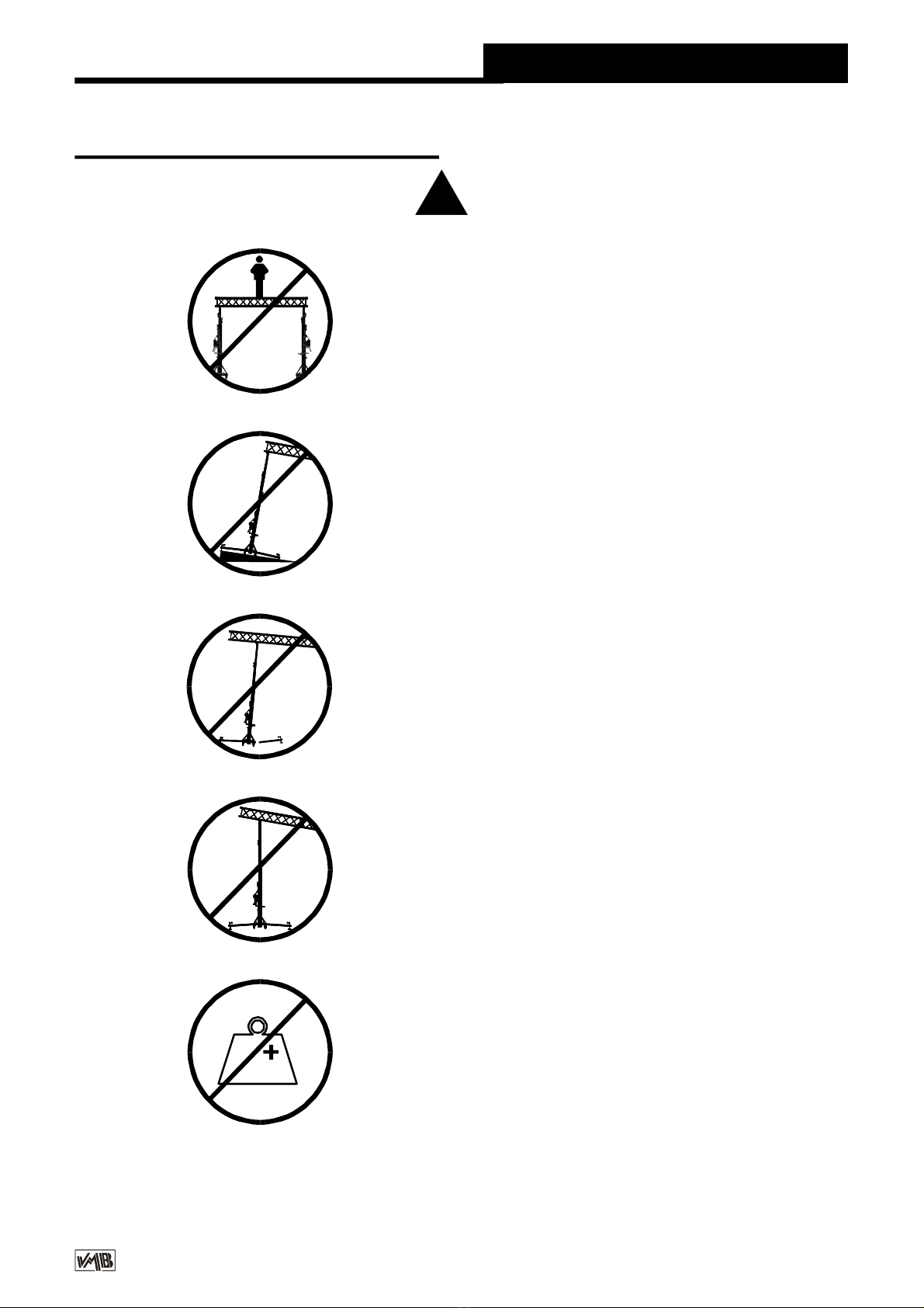
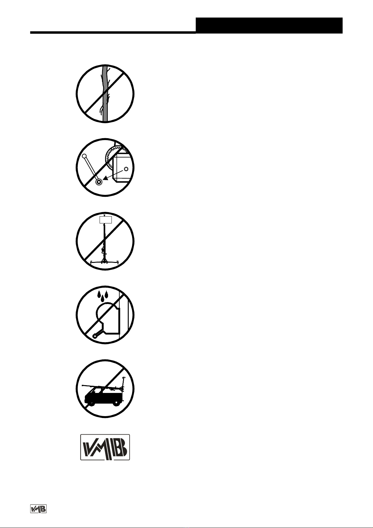
3. Normas de seguridad. !
3.1 - El elevador es un elemento industrial
diseñado para la elevación de cargas en
sentido vertical, NUNCA se debe utilizar
como plataforma elevadora de personas.
3.2 - Colocarelelevadorsóloensuperficies
duras y planas, verificando que está en
posición vertical.
Nunca utilice cuñas ni elementos extraños
para equilibrar el elevador.
3.5 - No se debe sobrepasar la capacidad
de cargamáximaindicada en la etiqueta de
características del elevador y en este
manual de instrucciones.
3.4 - Nunca se debe elevar una carga sin
antes verificar que está correctamente
apoyada y centrada en los soportes eleva-
dores adecuados, de forma que el peso de
la carga sólo actúe en sentido vertical.
3.3 - Comprobar que las patas están
correctamente montadas y sujetas por sus
pasadores retenedores de seguridad.
Si se utilizan los estabilizadores laterales,
comprobar que quedan correctamente
insertados y asegurados.
Kgs

v10.12 - Depósito legal y Copyright 2010. Todos los derechos reservados.
PRO LIFTS S.L.
Manual de instrucciones ESPAÑOL
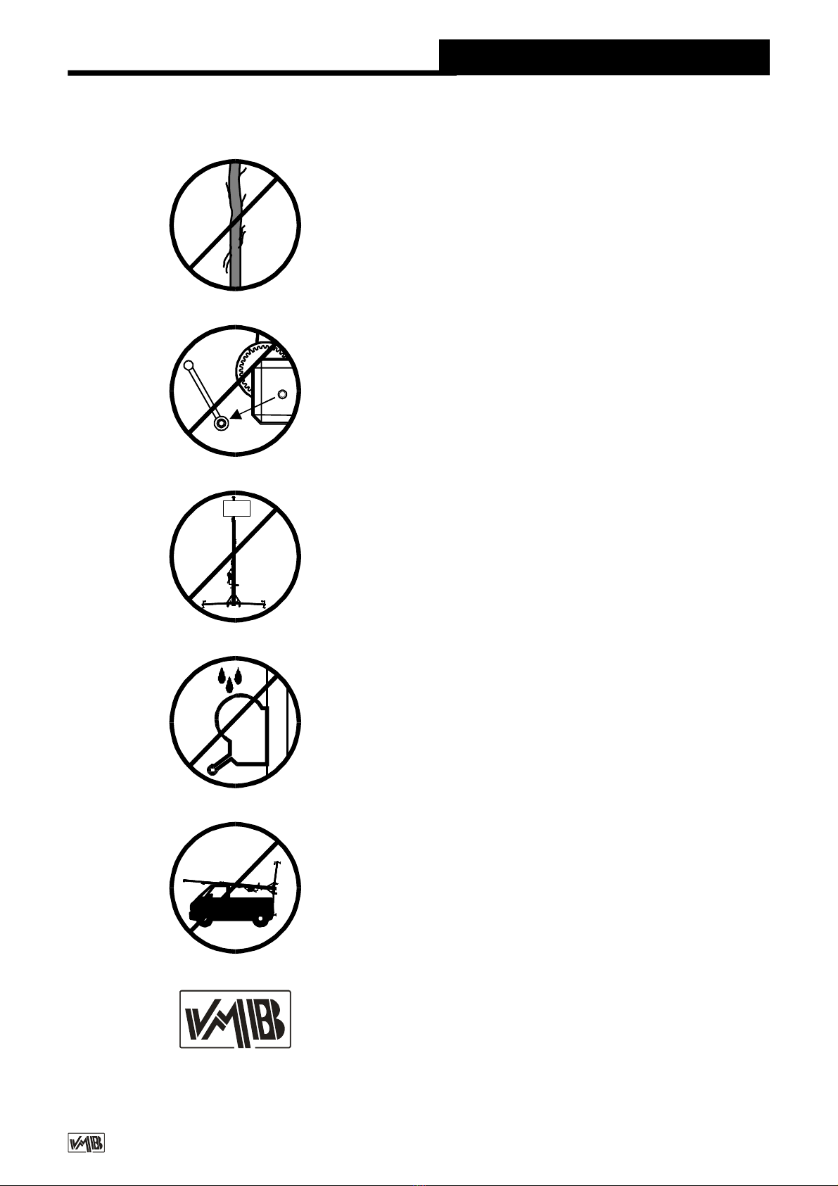
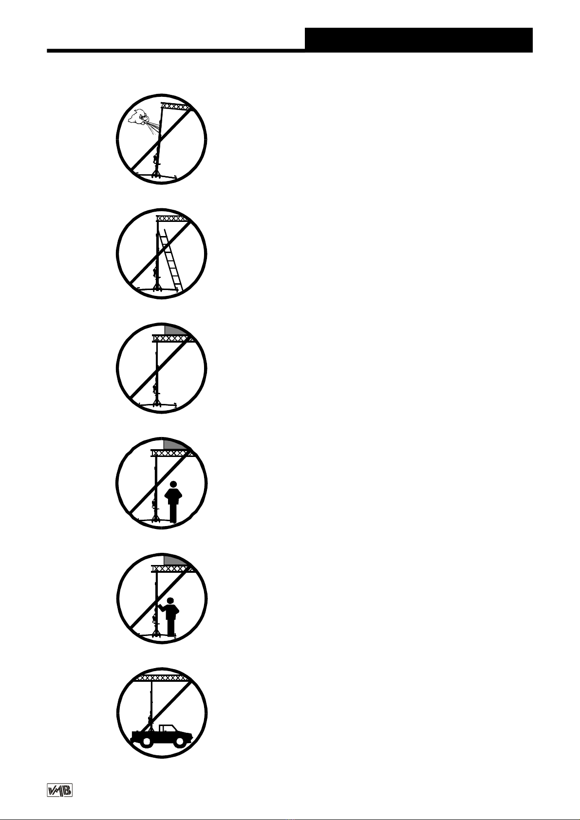
3.11 - Nunca utilizar el elevador sobre
ninguna superficie móvil o vehículo.
3.6 - Si existe posibilidad de viento fuerte o
en ráfagas, coloque el elevador en suelo
firme y asegúrelo con la ayuda de tirantes.
Nunca fije un tirante sobre un vehículo ni
cualquier otro elemento que pueda
desplazarse.
3.10 - Nunca sedebe desplazar el elevador
si éste se encuentra con la carga elevada.
No es aconsejable realizar ningún tipo
de movimiento, ni tan siquiera pequeños
ajustes de posicionamiento.
3.8 - Tenga cuidado con todo tipo de
salientes por encima del elevador como
cornisas, balcones, letreros luminosos,
etc...
Es muy importante evitar la presencia de
cables por debajo de la altura de trabajodel
elevador.
3.7 - No usar escaleras encima del
elevador ni apoyarlas en él para realizar
ningún tipo de trabajo.
3.9 - Nunca se ponga debajo de la carga ni
permita la presencia de otras personas en
la zona de trabajo del elevador.
v10.12 - Depósito legal y Copyright 2010. Todos los derechos reservados.
PRO LIFTS S.L.
Manual de instrucciones ESPAÑOL
3.12 - Antes de utilizar el elevador, verificar
el estado del cable, éste no debe presentar
rotura de hilos o aplastamiento. No usar
NUNCA cables defectuosos y en caso de
duda cambie el cable. Sólo utilice cable de
acero según DIN 3060. Calidad 180 Kg/
mm2resistente a la torsión.
3.16 - Para el transporte del elevador hay
que bajar todos los tramos.
3.15 - No engrasarni lubricar el mecanismo
de freno del cabrestante. Los discos de
freno, han sido engrasados con una grasa
especial resistente al calor y la presión.
No deben ser utilizados otros productos
para evitar influir negativamente en el
funcionamiento del freno.
3.14 - La carga mínima para un funciona-
miento del freno sin problemas esde25 Kg.
Sin esta carga mínima el freno no actuará.
3.13 - No desmontar nunca la manivela del
cabrestante (W) si el elevador está con
carga y elevado.
3.17 - Solamente deben utilizarse piezas
de repuesto VMB originales.
ORIGINAL
-25

v10.12 - Depósito legal y Copyright 2010. Todos los derechos reservados.
PRO LIFTS S.L.
Manual de instrucciones ESPAÑOL
4. Instrucciones de uso.
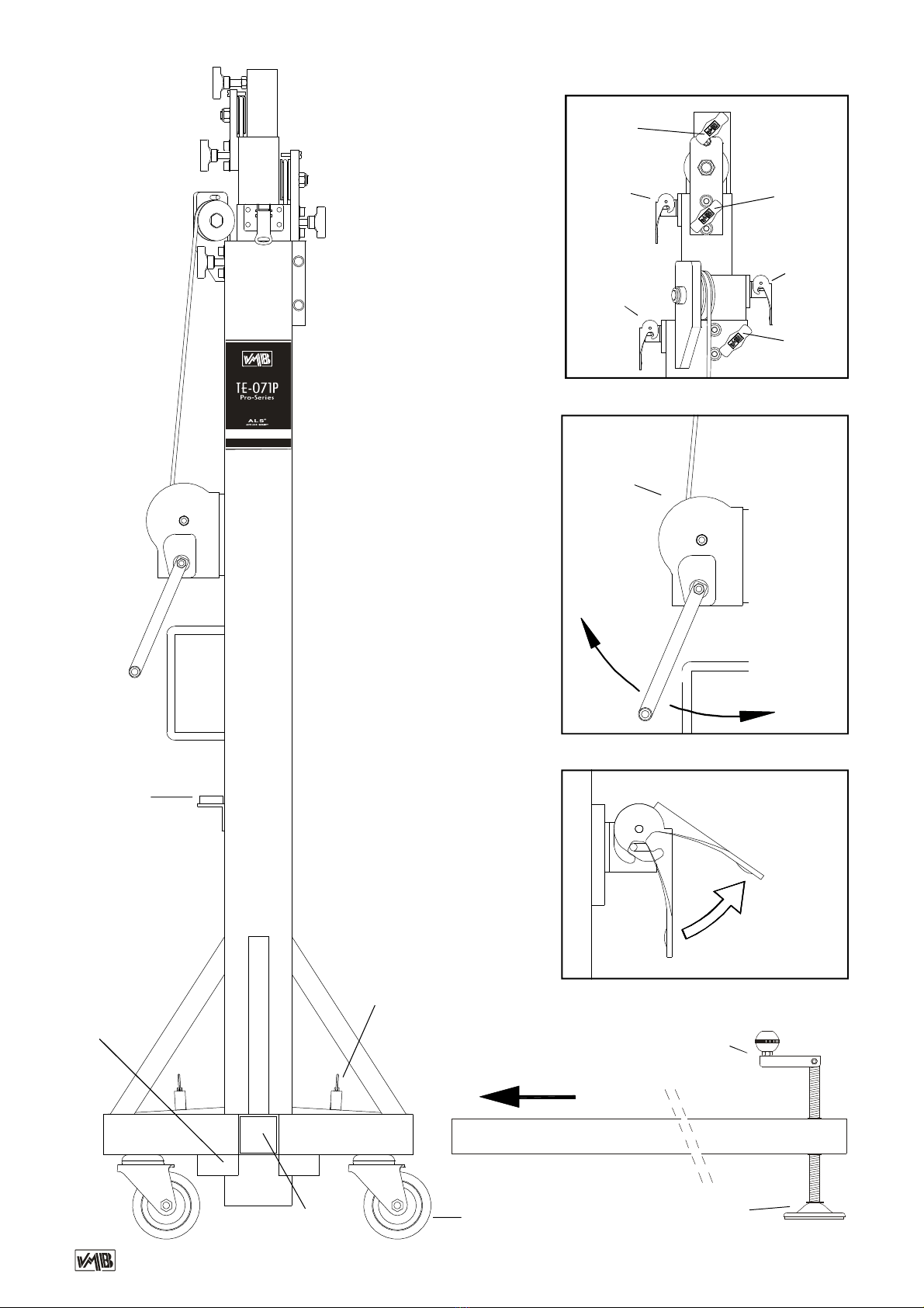
4.1 - Colocar la torre elevadora apoyada en
las ruedas direccionables de transporte (T)
sobre una superficie plana y firme en su em-
plazamiento de trabajo.
4.2 - Sacar las patas (P) de su soporte para
transporte (S) e insertarlas a fondo en sus
alojamientos de trabajo (V) comprobando que
quedansujetas por los gatillos retenedores de
seguridad. (R).
4.3 - Ajustar la posición vertical de la torre
mediante los platillos de apoyo regulables (Q)
girando las manivelas (H) en el sentido nece-
sario para lograr que la burbuja del indicador
de nivel (F) quede centrada en el círculo.
4.4 - Liberar los tramos aflojando las palomi-
llas de retención PR. Colocar la carga a
elevar sobre la torre mediante un soporte
adecuado según el caso, de forma que el
peso de la carga sólo actúe en sentido verti-
cal. La carga deberá ser como mínimo de 25
Kg. Esta quedará bloqueada automáticamen-
te en cualquier posición por el sistema auto-
mático de seguridad Auto-Lock.
4.5 - Elevar:
Girar la manivela del cabrestante (W)en
el sentido de las agujas del reloj (N1),
elevando la carga hasta la posición deseada,
comprobando que los gatillos del sistema
Auto-Lock van enclavándose, fijando
automáticamente los tramos.
4.6 - Descenso:
Liberar el gatillo deseguridad(M1).Para
liberarlosgatillosdeseguridadhayqueelevar
ligeramente la carga con el cabrestante para
soltarlos. En la posición normal de trabajo, el
peso de la carga impide liberar los gatillos.
Una vez desbloqueado el gatillo de seguridad
(M1), girar la manivela del cabrestante en
sentido contrario a las agujas del reloj (N2)
hasta que descendiendo la carga, quede ba-
jado al máximo el tramo 1. Liberar el gatillo
(M2) y seguir bajando la torre hasta que éste
segundo tramo baje al máximo. Desbloquear
el gatillo (M3) y seguir bajando la carga hasta
que la torre quede completamente plegada a
su altura mínima.
La torre puede dejarse en cualquier po-
sición intermedia que se necesite del mismo
modo que al subir la carga.
4.7 - Para transportar la torre es necesario
plegarla bajando completamente los tramos y
fijarlos con las palomillas de retención PR.
Desmontar las patas liberando los gatillos de
retención y colocarlas en su posición de
transporte (S).

v10.12 - Depósito legal y Copyright 2010. Todos los derechos reservados.
PRO LIFTS S.L.
Manual de instrucciones ESPAÑOL
5. Mantenimiento.
5.1 - Comprobar periódicamente el estado
del cable. Si un cable presenta rotura de
hilos o aplastamiento, debe ser sustituido
inmediatamente por otro nuevo. No utilizar la
torre elevadora con cables en mal estado.
Utilizar sólamente cable de acero DIN
3060 resistente a la torsión.
5.2 - La torre elevadora se suministra
completamente engrasada de fábrica.
No obstante, se recomienda engrasar
periódicamente según el uso, la corona
dentada del cabrestante, los cojinetes del
arbol de accionamiento y el buje, la rosca
de la manivela y los tramos.
ATENCION:
No engrasar ni lubricar el mecanismo
del freno.
Los discos de freno, han sido engrasa-
dos con una grasa especial resistente al calor
y la presión. No deben ser utilizados otros
productos paraevitar influir negativamenteen
el funcionamiento del freno.
No es necesario engrasar los discos de
freno.
5.3 - La torre elevadora TE-071, debe ser
comprobada por un experto como mínimo
una vez al año de acuerdo con su utilización.
5.4 - Sólamente deben utilizarse piezas de
repuesto originales para garantizar una
continuada seguridad de uso.
El usuario pierde todos los derechos de
garantía, si incorpora otros repuestos que
no sean originales o lleva a cabo cualquier
modificación en el producto.
5.5 - Para solicitar cualquier pieza de
repuesto, debe indicarse su número de
referencia, que figura en las hojas finales de
despiece de este manual.
7. Certificaciones
-
Directiva de maquinas:
89/392/CE y98/37/CE
-BGV C1 (GUV-VC1) / BGG 912 (GUV-G912)
6. Garantía.
El periodo de garantía de esta torre elevadora
es de dos años, a partir de la fecha de compra.
PRO LIFTS S.L. se compromete, a partir
deestafechayduranteel periododegarantía,
a eliminar todos los fallos que puedanapare-
cer producidos por defectos de los materiales
o de la fabricación.
No están incluidos en la garantía los
daños producidos por un uso indebido,
modificacionesdelproducto,manipulaciónpor
terceros o siniestro natural o accidental.
v10.12 - Depósito legal y Copyright 2010. Todos los derechos reservados.
PRO LIFTS S.L.
Operating instructions ENGLISH
CONTENTS
1. Introduction.
2. Technical information.
3. Safety precautions.
4. Operation.
5. Maintenance.
6. Guarantee
7. Certificaciones
1. Introduction.
Dear customer,
In order to facilitate a reliable operating of
towerlift TE-071, we have created these
operatinginstructions.
Before use, you are required to read the
operating instructions.
Please note the technical data.
Our products undergo very rigorous testing
under strict conditionsand they are monitored
continuously during the manufacturing
process.
In order to guarantee the lift function and
safety, the original parts of the manufacturer's
design must be used. If any parts other than
those of the manufacturer are used, or the
product is modified in any way, the user
forfeits all warranty rights to claim.
We reserve the right to modify design and
performance without prior notice. When
contacting us with queries or ordering
spare parts the model type, year of
manufacture, and serial number are to
be quoted.
2. Technical information.
2.1 - Towerlift TE-071B / TE-071S.
2.2 - Designed to lift loads vertically up to
different heights as support for sets of
illumination.
2.3 - Maximum load : 220 Kg (485lb).
2.4 - Minimum load : 25 Kg (55lb).
2.5 - Maximum height : 5,35 m (17.5’).
2.6 - Minimum height : 1,73 m (5.7’).
2.7 - Area of base : 2,1 x 2,1 m (6.8 x 6.8’).
2.8 - Transport weight : 71 Kg (157lb).
2.9 - Construction material : Steel profiles DIN
2394.
2.10-Fourprofilestelescopicsystemoperated
by cable of steel and guided by channelled
steel pulleys with ball bearings.
2.11 - Winch : 450 Kg. of maximum load with
automatic brake to stop the load.
Certification CE and GS TÜV.
2.12 - Cable : Steel DIN 3060. Quality 180 Kg/
mm2. Twisting - resistant.
2.13 - Cable diameter : 6 mm.
2.14 - Exclusive ALS system ( Auto-Lock
Security ).
2.15 - Adjustable stabilizing disc feet in the
legs with ruber non slip supports.
2.16 - Anchor of the legs by safety catches.
2.17 - Spirit level to adjust the verticallity of the
tower.
2.18 - Finishing and protection with black
polyester.
2.19 - Swivel wheels for the vertical transport
of the tower to its working location when
folded.

v10.12 - Depósito legal y Copyright 2010. Todos los derechos reservados.
PRO LIFTS S.L.
Operating instructions ENGLISH
3. Safety precautions. !
Kgs
3.1 - The TE-071 is a machine designed to
elevateloadsupwardsinaverticaldirection,
NEVER should it be used as a platform to
elevatepeople.
3.2- Only placethe liftonhard,flatsurfaces
alwayscheckingthatitisinaverticalposition
byusingthebubblelevelindicator(F) found
on the base section. Adjust the outrigger
stabilisers (Q) by turning the cranks to level
if necessary. NEVER use wedges or other
foreignobjectstobringthelifttoequilibrium.
3.5 - The maximum load indicated on the
characteristics label and the instructions
manual should not be exceeded
3.4 - NEVER should the lift be used to
elevate a load that has not been properly
checked. It is necessary to verify that the
load is correctly supported and centred on
theappropriateliftsupportsothattheweight
of the load will only elevate in a vertical
direction.
3.3 - Check that the outriggers are placed
and set-up correctly using the pins safety
system.

v10.12 - Depósito legal y Copyright 2010. Todos los derechos reservados.
PRO LIFTS S.L.
Operating instructions ENGLISH
3.11 - NEVERuse thelift on avehicle orany
other mobile surface.
3.6 - If there is a possibility of strong winds
or gusts, place the lift on the ground firmly
and secure itwith the use ofstraps. NEVER
attach a strap to a vehicle or any other
object that can possibly be moved.
3.10 - NEVER move the lift whilst it is
carrying a load. It is not advisable to carry
out any type of movement even small
positional adjustments.
3.9 - NEVERallowany teammember below
theloadoranybodyelseintheliftsoperating
zone.
3.8 - Take care with all obstacles above the
lift and its extension zone such as cornices,
balconies, and luminous signboards. It is
very important to avoid the presence of all
types of cables below the extended lift.
3.7 - Do not use stepladders on the lift or
use it as a support for them.
v10.12 - Depósito legal y Copyright 2010. Todos los derechos reservados.
PRO LIFTS S.L.
ORIGINAL
-25
3.12 - Before using the lift, check the state
of the cable. The cable should not contain
broken threads or show any signs of
crushed/flattenedareas.NEVERusefaulty
cables, always change them if there is any
doubt. Only use steel cables reference:
DIN 3060. Quality: 180KG/mm and torsion
resistant.
3.16 - All sections must be lowered during
transportation.
3.15 - Do notgreaseor lubricate thewinch’s
breakingmechanism. The brakediskshave
been greased with a special heat and
pressure resistant solution. Other products
should notbeusedto avoidnegative effects
regarding the braking mechanism.
3.14 - The minimumload to avoid problems
regardingthebreakingmechanismis25KG.
Without this load the brake will not work.
3.13 - NEVER take apart the crank of the
winch when the lift is carrying a load or
extended.
3.17-Onlyoriginalreplacementpartsshould
be used.
Operating instructions ENGLISH

v10.12 - Depósito legal y Copyright 2010. Todos los derechos reservados.
PRO LIFTS S.L.
Operating instructions ENGLISH
4. Operation.
4.1 - In order to place the elevator tower in
their working location, put the tower leaned in
their transport wheels (T) on a hard and level
surface.
4.2 - Get on the legs (P) of their support for the
transport (S) and insert them in their working
lodging (V) verifying that they are tightly
fastened by the safety catches (R).
4.3 - Adjust the vertical position of the tower by
means of the disc feet supports (Q) rotating
the hand crank (H) in the necessary direction
to manage that the bubble of the spirit level (F)
stays centred in the circle.
4.4 - Release the profiles turning the retention
crank nob PR. Put the load on top of the tower
using the suitable support, in order to make
work the weight of the load only in the vertical
direction. The minimum load must be 25 Kg.
The load will be automatically locked in any
position.
4.5 - Lifting:
Elevatethetowerrotatingthehandcrank
of the winch (W) clockwise (N1), lifting theload
up to desired height.
4.6 - Lowering:
When lowering the towerlift you must lift
the load some cm until the ALS lock becomes
free. Then pull up the locking pin on the ALS
safety catch (M1) and rotate the hand crank of
the winch counterclockwise (N2) lowering the
load until the profile is completely folded.
Repeat the above process to each section
until all are completely lowered.
Pull up the locking pin on the ALS safety catch
(M2) and continue lowering the tower until this
second profile is completely folded.
Pull up the locking pin on the ALS safety catch
(M3) and continue lowering the load until the
towerlift is completely folded down to its
minimum height.
The towerlift can be left in any
intermediate position which would be
necessary.
4.7 - To transport the lift you must lower all the
profiles completely, locking them with the
retention crank nob PR. Get out the legs
lifting the blockade on the catches and put
them in their transport lodging (S).

v10.12 - Depósito legal y Copyright 2010. Todos los derechos reservados.
PRO LIFTS S.L.
Operating instructions ENGLISH
5. Maintenance.
5.1 - The cable is to be regulary checked for
wear(ie:kinks,singlestrundbreakage).Faulty
cables must be replaced immediately. Do not
use the elevator tower with faulty cables.
Only use handle cables DIN 3060.
5.2 - Theelevator tower has been lubricated in
theworkshop.Itisneverthelessrecommended
that oil is regulary applied to the gear drive, the
bearing bushes on the drive shaft and to the
drum hub, the thread of the handle and the
profiles of the tower.
ATTENTION:
Do not apply oil or grease to the brake
mechanism.
The brake washers have been
pregreased with an special warmth and
pressure resistant grease. Do not use other
greases as this will effect the winch brake
performance.
It is not necessary greasing the brake
washers.
5.3 - The elevator tower TE-071 must be
inspected by trained personnel at least once
annually.
5.4 - In order to maintain this guarantee of
function and safety, original parts of the
manufacturer's design must be used.
The user forfeits all rights to claimif parts
other than those of the manufacturer are used
or modifies the product in any other way.
5.5 - When any spare part would be required,
itisnecessarytoindicateitsreferencenumber,
wich is included in the spare parts of this
manual.
7. Certifications
-
EC Machinery Directive
89/392/ECC and 98/37/ECC
- BGV C1 (GUV-VC1) / BGG 912 (GUV-G912)
6. Guarantee.
If the during the guarantee period because of
poor workmanship or faulty materials PRO
LIFTS S.L. will repair or replace it.
The guarantee period for Europe is at 2
years.
The guarantee does not cover damage
caused by improper use, wear and tear
unauthorised repairs.The guarantee doesnot
cover consumables or defects that have only
a negligible effect on the value or operation of
the elevator tower.

v10.12 - Depósito legal y Copyright 2010. Todos los derechos reservados.
PRO LIFTS S.L.
Bedienungsanleitung DEUTSCH
Inhaltsverzeichnis
1. Einführung.
2. Technische Daten.
3. Sicherheitsmaßnahmen.
4. Bedienungsanleitung.
5. Wartung.
6. Garantie.
7. Zertifikat.
1. Einführung.
Sehr geehrte Damen und Herren,
die vorliegende Betriebsanleitung
wurdemitdemZweckerstellt,einezuverlässige
Bedienung des TE-071 Hebeturms zu
ermöglichen. Lesen Sie bitte die
Betriebsanleitung vor Inbetriebnahme
sorgfältig durch.
Bitte beachten Sie auch die technische Daten.
Unsere Produkte unterliegen strengsten
Prüfungen und Kontrollen bei der Fertigung.
Es sind ausschließlich Original-Ersatzteile zu
verwenden. Für den Anwender werden alle
Gewährleistungsansprüche aufgehoben,
wenn er Nicht-Original-Ersatzeile verwendet
bzw.ÄnderungenamProduktselbstvormimmt.
2. Technische daten.
2.1 - Hebeturm, Typ TE-071B / TE-071S.
2.2 - Das Gerät ist zum senkrechten Heben
von Lasten, wie auf verschiede Höhen,
konzipiert worden.
2.3 - Zulässige Hubkraft : 220 Kg.
2.4 - Mindesthublast : 25 Kg.
2.5 - Zulässige Hubhöhe : 5,35 m.
2.6 - Mindeshubhöhe : 1,73 m.
2.7 - Grundplattenfläche : 2,10 x 2,10 m.
2.8 - Transportgewicht : 71 Kg.
2.9 - Werkstoff : Stahlprofil nach DIN 2394.
2.10 - Teleskopierbares System, bestehend
aus vier, von einem über genufete Rollen mit
WälzlagerngeführtenStahlseilangetriebenen
Abschnitten.
2.11- Die Winde,mit einer zulässigen Hublast
von 450 Kg, ist mit einer automatischen
Lasthaltebremse ausgestattet.
CE und GS TÜV.
2.12 - Seil : aus Stahl nach DIN 3060. Güte
180 Kg/mm2verwindungssteif.
2.13 - Seildurchmesser : 6 mm.
2.14 - Exklusive ALS System ( Auto-Lock
Security ).
2.15 - Ausleger mit verstellbaren Spindeln
und rutschfesten Gummifüßen.
2.16 - Verankerung der Ausleger über
Sicherheitsklinken.
2.17 - Wasserwaage zum Einstellen der
senkrechten Turmlage.
2.18-OberflächeundSicherunginschwarzem
Polyester.
2.19 - Transportrollen zum Bewegen des
Turms bei senkrechter und eingefahrener
Stellung zur Arbeitsstelle.

v10.12 - Depósito legal y Copyright 2010. Todos los derechos reservados.
PRO LIFTS S.L.
3. SICHERHEITSMAßNAHMEN. !
3.1 - Der TE – 071 wurde konzipiert zum
Heben und Senken von vertikalen Lasten.
Nutzen Sie Ihn niemals zur Beförderung
von Personen.
3.2 - Achten Sie darauf, das derTL – Tower
auf festem, geradenUntergrund steht. Und
vergewissern Sie sich mit Hilfe der
Wasserwaage (F), dass er eine vertikale
Position zumBoden eingenommen hat.Bei
Bedarf mittels des Stelltellers (Q) durch
Drehen der Spindelkurbel (H) die
entsprechende Tunlage einstellen.
3.5 - Die zulässige Höchstlast, die Sie auf
den Typenschild, welche sie in der
Bedienungsanleitung finden, darf niemals
überschritten werden
3.4 - Niemals sollten Sie eine ungesicherte
Ladung heben. Vergewissern Sie sich
immer, das die Ladung zentriert auf der
GabelaufliegtundnurinvertikalerRichtung
hebt!
3.3 - Vergewissern Sie sich, dass die
Auslegerrichtig eingestecktsindundnutzen
Sie die Rastbolzen zum feststellen!
Bedienungsanleitung DEUTSCH
Kgs
v10.12 - Depósito legal y Copyright 2010. Todos los derechos reservados.
PRO LIFTS S.L.
3.11 - Es ist nicht gestattet den Lift auf
einemFahrzeugmiteinenmobilenUnterbau
zu installieren!
3.6 - Bei Freiluftanwendungen den Turm
auf festen Boden stellen und mittels
Seilanker gegen Windbelastung sichern.
NiemalsanFahrzeugendieAbspannungen
befestigen oder an Gegenständen, die
ausweichen könnten.
3.10 - Bewegen Sie den Lift niemals unter
Belastung.
3.8 - Achten Sie auf alle Gegenstände im
oberen Hubbereich des Liftes. Achten Sie
aufBalkone,Leuchtschriftenundbesonders
auf stromführende Kabel.
3.7 - Stellen Sie niemals Leitern an den
Tower.
Bedienungsanleitung DEUTSCH
3.9 - Halten Sie sich niemals während des
Hebens und Senkens in Gefahrenbereich
auf.

v10.12 - Depósito legal y Copyright 2010. Todos los derechos reservados.
PRO LIFTS S.L.
3.12 - Vor Gebrauch Seilzustand
kontrollieren.DasSeil darfkeineSeilbrüche
oder Quetschungen aufweisen. Es dürfen
auf keinem Fall Seile in einem schlechten
Zustand verwendet werden.
3.16 - Alle Angebauten Teile sind für den
Transport einzufahren.
3.15- Ölen oder Fetten der Fallbremsen ist
zu unterlassen, da diese mit einem Druck
und Hitzebeständigen Material bearbeitet
wurden. Andere Werkstoffe führen in der
Handhabung zu negativen Effekten.
3.14 - Die maximale Belastung zur
Überprüfung der Sicherungen ist 25 kg.
Ohne Belastung ist die Überprüfung nicht
möglich.
3.13 - Niemals die Winde, oder Teile der
Winde unter Belastung demontieren.
3.17 - Es sind ausschließlich Original
Ersatzteile zu verwenden. Für den
Anwender werden alle
Gewährleistungsansprüche aufgehoben,
wenn nicht Original Ersatzteile verendet
bzw.Änderungen an Produkten
vorgenommen werden.
Bedienungsanleitung DEUTSCH
ORIGINAL
-25

v10.12 - Depósito legal y Copyright 2010. Todos los derechos reservados.
PRO LIFTS S.L.
Bedienungsanleitung DEUTSCH
4. Bedienungsanleitung.
4.1 - Den Hebeturm auf den Transportrollen
(T) abgestützt auf eine ebene und festeFläche
an der Arbeitsstelle aufstellen.
4.2 - Die Ausleger (P) aus der
Transporhalterung (S) herausnehmen und in
derenArbeitsaufnahmen(V)voll einschieben.
Dabei achten Sie bitte darauf, daß sie mittels
der Sicherheitsbolzen (R) befestigt sind.
4.3 - Die senkrechte Turmlage über die
verstellbaren Spindel (Q) durch Drehen der
kurbel (H) in entsprechender Richtung zum
Zentrieren der Wasserwaagenblase (F) an
der Kreismitte einstellen.
4.4 - Entriegelung der Profile durch drücken
der rückhalte Knöpfe.
Die zu hebende Last auf dem Turm mittels
eines geeigneten Trägers so aufstellen, daß
das Lastgewicht nur senkrecht wirkt. Die
Mindestlast muß 25 Kg. betragen. Der lift
bleibt durch das automatische Auto-Lock-
System automatisch in jeder beliebigen
Position arretiert.
4.5 - Heben:
DenTurmdurchDrehenderWindekurbel
(W)imUhrzeigersinn(N1), auf die gewünschte
Höhebringen.PrüfenSiebitte,dassdieBolzen
des Auto-Lock-Systems in Schaltposition sind
und einrasten, so dass die Abschnitte
automatisch fixiert werden.
4.6 - Senken:
Den Sicherheitsbolzen (M1) entriegeln.
Umdie Sicherheitsbolzen zu entsperren, muß
man die Last mit der Winde leicht anheben. In
der normalen Arbeitsposition verhindert das
Lastgewicht das Entriegeln der Bolzen. Nach
dem Entriegeln des Sicherheitsbolzen (M1),
dieKurbelderWindegegendenUhrzeigersinn
(N2) drehen bis beim Senken der Last
Turmabschnitt 1 voll heruntergefahren ist.
Den Bolzen (M2) entriegeln und der Turm
weiter nach unten senken bis Abschnitt 2 voll
heruntergefahren ist.
Bolzen (M3) entriegeln und die Last weiter
senken bis der Heberturm vollkommen bis zur
Mindesthöhe heruntergefahren ist.
4.7 - Zum Transport des Liftes müssen alle
Profile komplett abgelassen werden und mit
dem Verriegelungsbolzen gesichert werden.
Die Ausleger entsperren und diese in ihre
Transportstellung (S) bringen.
This manual suits for next models
2
Table of contents
Languages:
Other PRO LIFTS Lifting System manuals

PRO LIFTS
PRO LIFTS VMB TL-054 Instruction Manual

PRO LIFTS
PRO LIFTS VMB TE-064 Instruction Manual

PRO LIFTS
PRO LIFTS VMB TE-086 Instruction Manual

PRO LIFTS
PRO LIFTS VMB TE-076 Instruction Manual

PRO LIFTS
PRO LIFTS VMB TE-074 Instruction Manual

PRO LIFTS
PRO LIFTS VMB HDT-8 Instruction Manual

PRO LIFTS
PRO LIFTS VMB TP-20 Instruction Manual

PRO LIFTS
PRO LIFTS VMB TL-A220 Instruction Manual

PRO LIFTS
PRO LIFTS VMB TL-A500 Instruction Manual

PRO LIFTS
PRO LIFTS VMB TL-075 Instruction Manual


