PRO LIFTS VMB TE-034 Instruction Manual
V.04.14
OPERATING INSTRUCTIONS USER MANUAL
MANUAL DE INSTRUCCIONES
TOWERLIFT
TORRE ELEVADORA
TE-034
GBE USA
LIFTING TOWER TE-034
TORRE ELEVADORA TE-034
PRO LIFTS S.L.
C/ Ciudad de Barcelona Nº19
Pol.Ind. Fuente del Jarro
46988 Paterna (Valencia)
Tlf Export: +34 96 171 81 86
Tlf Nacional: 96 171 81 83
Manufacturer - Fabricante
Este manual de usuario y catálogo anexo de piezas de repuesto es propiedad de PRO LIFTS S.L.
Queda prohibida su reproducción total o parcial por cualquier medio que la tecnología actual permita.
Deposito legal y copyright 2014. Todos los derechos reservados.
MADE IN SPAIN (EU)
BGV-C1
BGG-912
EC Conformity Declaration pursuant to the EC Machinery
Directives 89/392/CE and 98/37/CE: Manual lifters
Find a copy of the certifications at the end of this booklet.
Puede ver una copia de las certificaciones al final del manual.
CERTIFICATIONS / CERTIFICACIONES
Depósito legal y copyright 2014. Todos los derechos reservados. 3PRO LIFTS S.L.
BTE-034
ALS-1
N2
ALS-2 W
SA
N1
R
SA
K
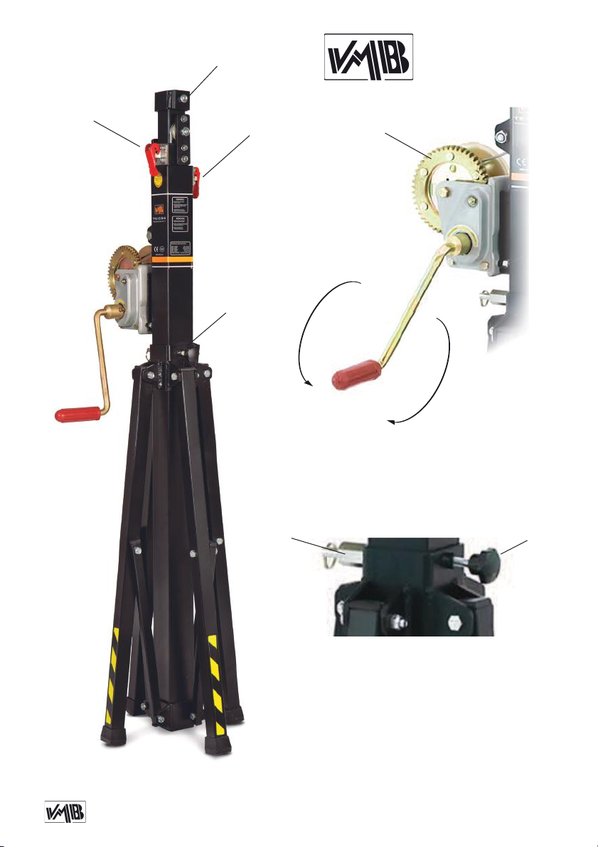
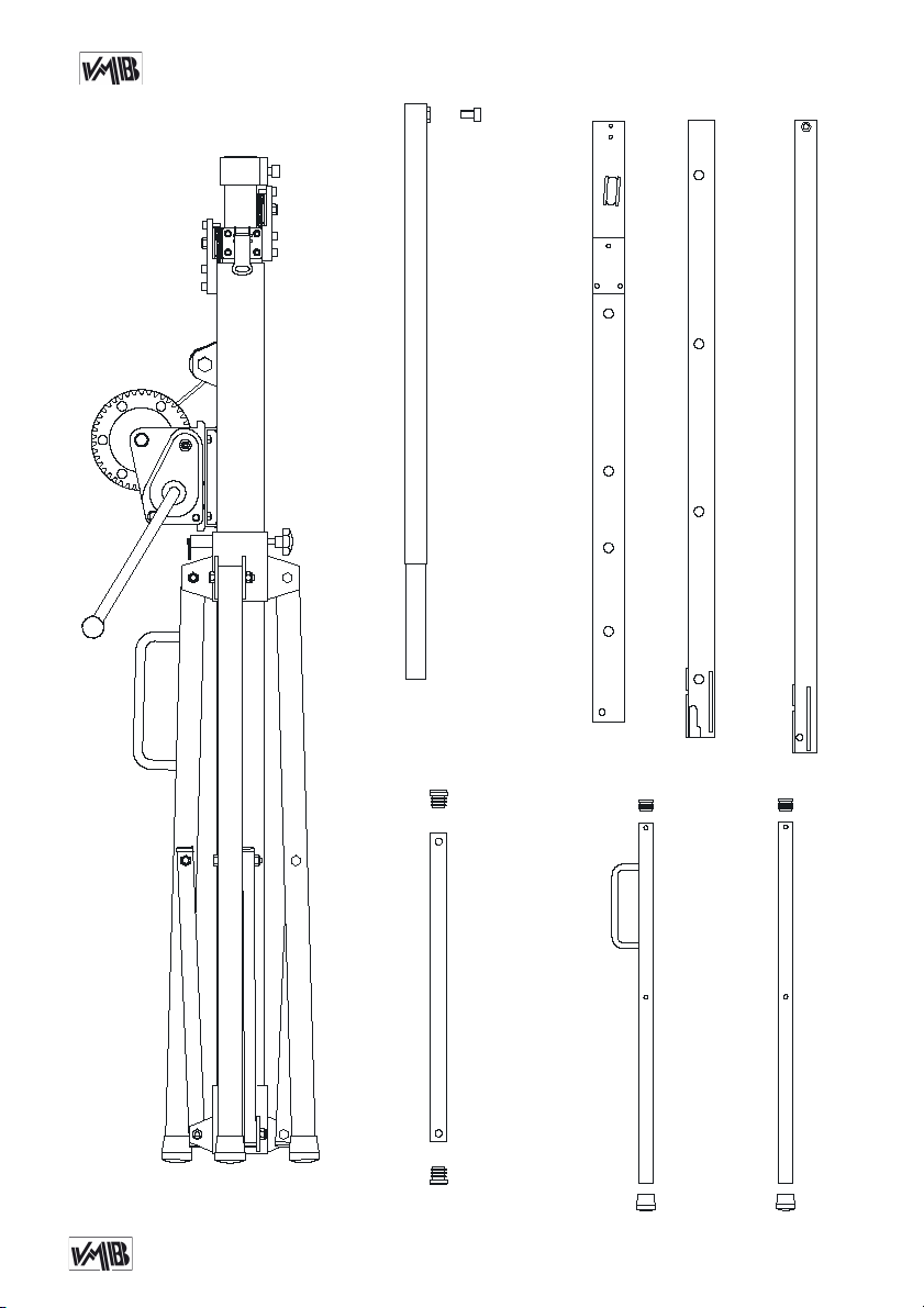
B: Steel bracket / Abrazadera de acero
ALS: Security lock / Gatillo seguridad
W: Winch / Cabrestante
N: Force on hand crank / Fuerza sobre manivela
SA: Support system / Soporte de apoyo
R: Catch pawl / Gatillo bloqueo posición SA
K: Knob / Pomo retenedor SA
Depósito legal y copyright 2014. Todos los derechos reservados. 4PRO LIFTS S.L.
Quick operation guide ENGLISH
CONTENTS
1. Introduction.
2. Technical information.
3. Safety precautions.
4. Operation.
5. Maintenance.
6. Guarantee.
1. INTRODUCTION
Dear customer,
In order to ensure a safe and reliable ope-
ration of the TE-034 towerlift please follow
the instructions in this booklet carefully.
Before operating the lift, read the instruc-
tions completely and please note the te-
chnical information contained within this
manual.
All VMB products undergo very rigorous
testing, under strict conditions and they
are monitored continuously during the ma-
nufacturing process.
In order to guarantee the lifts function and
safety, only original parts from the manu-
facturer must be used. If any parts other
than those of the manufacturer are used,
or the product is modified in any way, the
user forfeits all warranty rights to claim.
VMB reserves the right to modify the pro-
duct specifications without prior notice.
The model type, production year and se-
rial number must be quoted in any queries
or orders for spare parts.
2. TECHNICAL INFORMATION
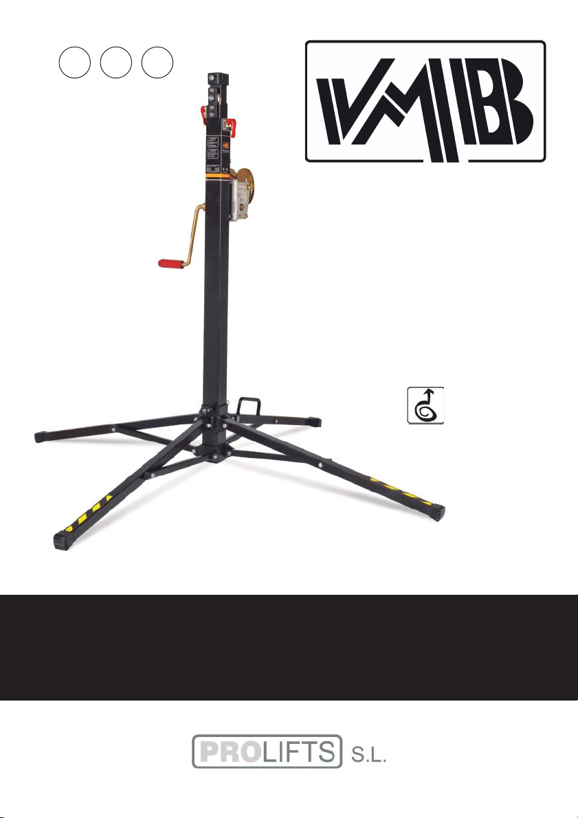
2.1 - TE-034 Towerlift.
2.2 - Designed to lift loads, such as trus-
sing and lighting, vertically up to
different heights.
2.3 - Maximum load : 125 Kg (275 lb).
2.4 - Minimum load : 25 Kg (55 lb).
2.5 - Maximum height : 3.8 m (12.5’).
2.6 - Folded height : 1.26 m (4.1’).
2.7 - Area of base : 1.5 x 1.5 m
(4.9’ x 4.9’).
2.8 - Unit weight : 21 Kg (47 lb).
2.9. - Adaptator: Ø 35 mm
(PSU-034/PSU-06).
2.10 - Construction material : Steel profi-
les DIN 2394.
2.11 - Three telescopic profile system ope-
rated by steel cable and guided by chan-
nelled steel pulleys with ball bearings.
2.12 - Winch: 450 Kg (990 lb). maximum
load with automatic brake. Certification
CE and
GS TÜV.
2.13 - Cable : Steel DIN 3060. Quality 180
Kg/mm2twist resistant.
Cable diameter : 4 mm.
Depósito legal y copyright 2014. Todos los derechos reservados. 5PRO LIFTS S.L.
Quick operation guide ENGLISH
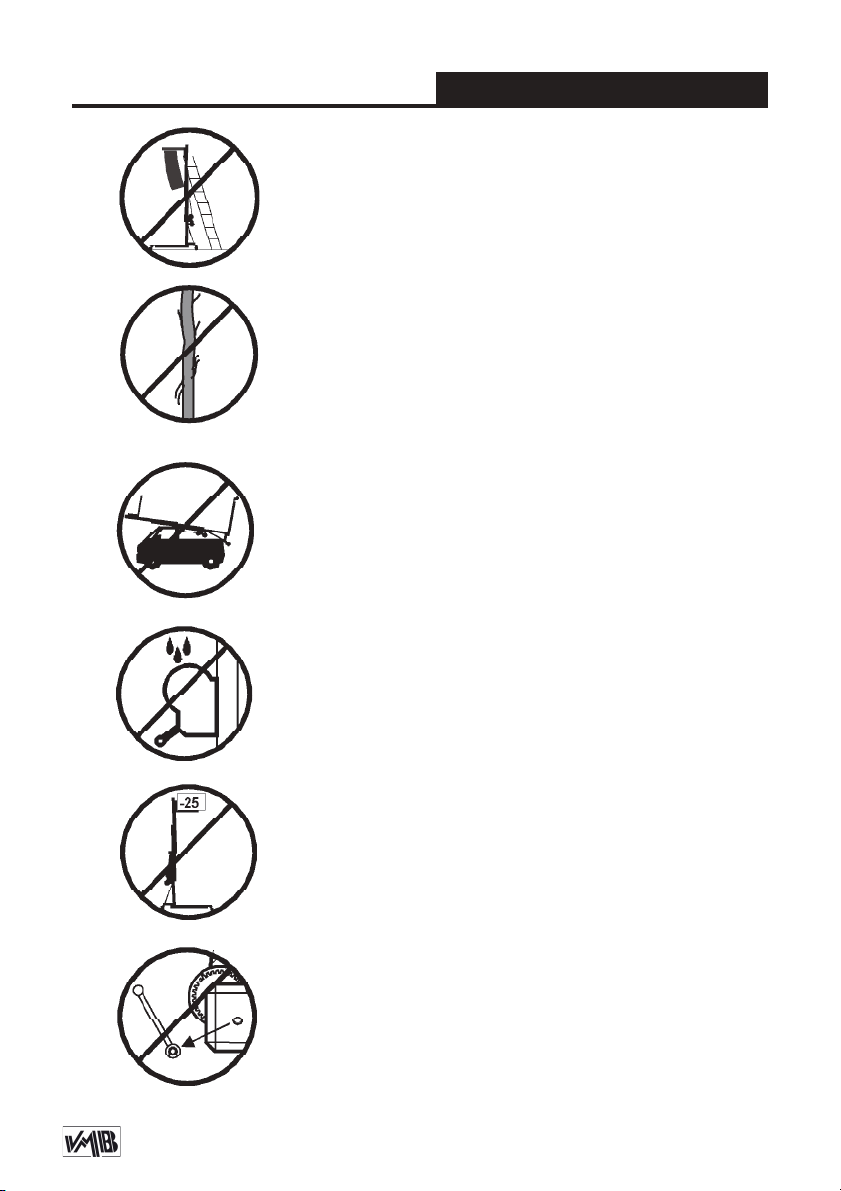
3. SAFETY PRECAUTIONS.
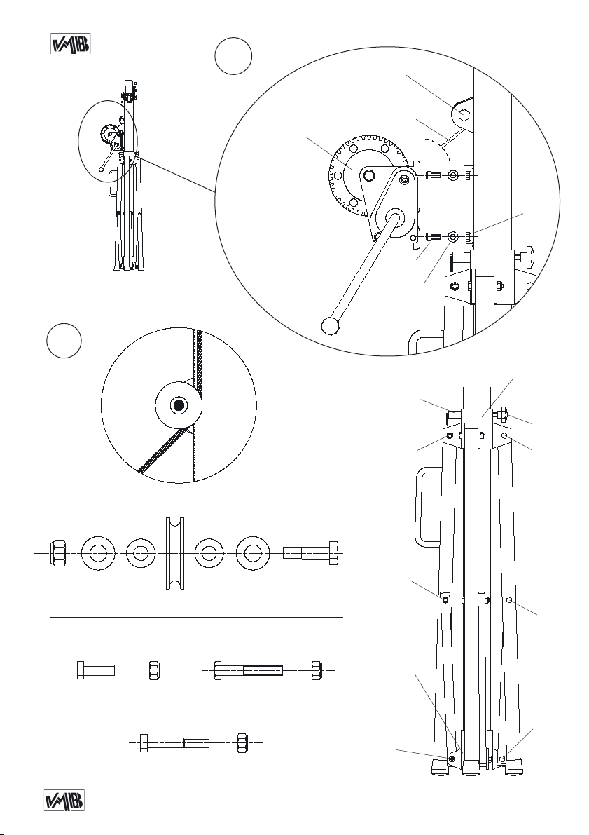
2.14 - Exclusive ALS system (Auto-Lock
Security), pat. pen. 200501056.hed in sa-
tin polyester.
2.15 - Legs with plastic end caps.
2.16 - Anchor of the support system of the
legs via safety catch and knob.
2.17 - Antirust protection, primed paint
with cured polyester dust cover. The tower
can be supplied with natural aluminium
finish or black (version B).
2.18 - Extension bar (EX-034B) included,
attached to the leg by a magnet.
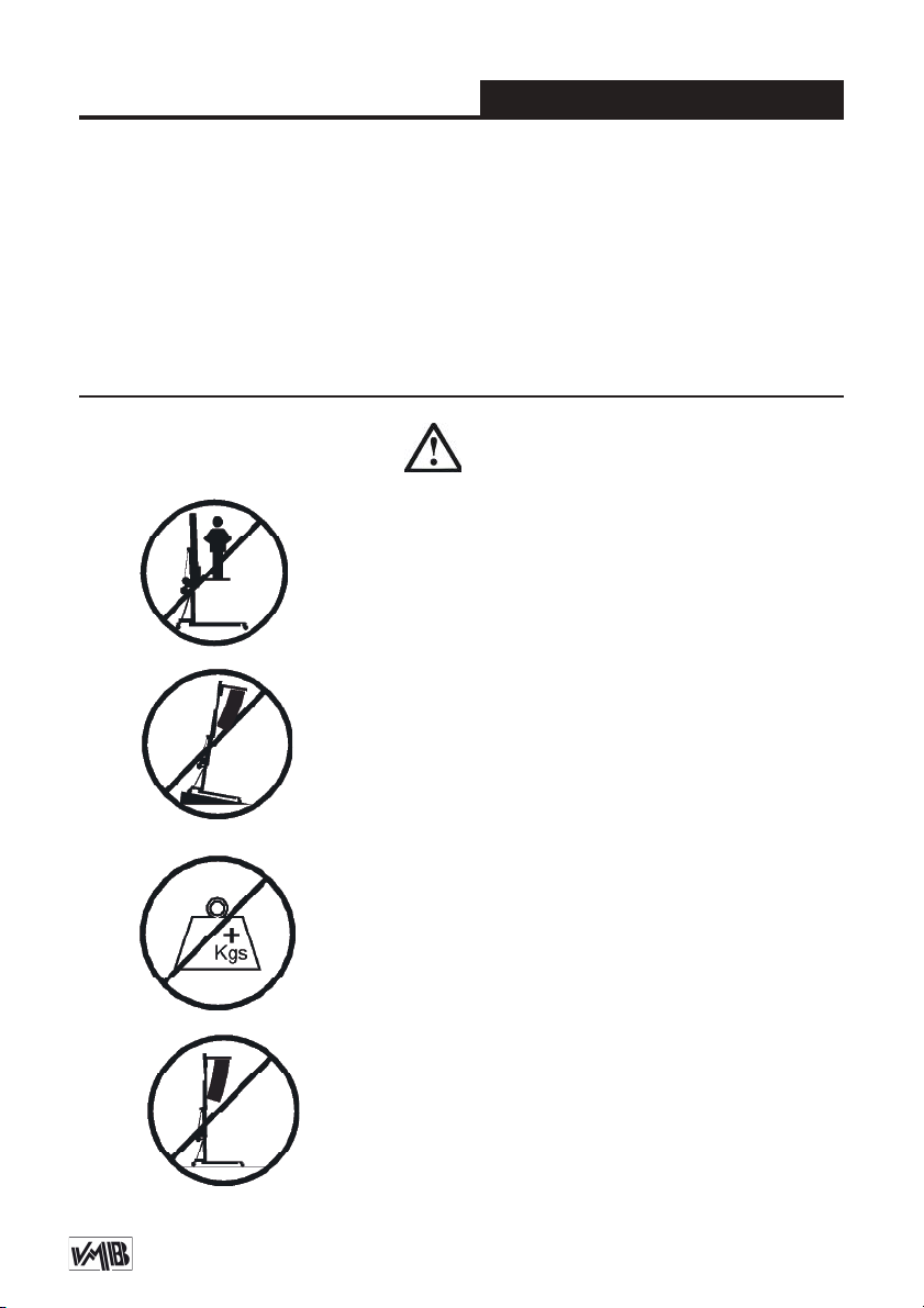
3.1 - The TE-034 is a machine designed to elevate
loads upwards in a vertical direction, It should NEVER
be used as a platform to elevate people.
3.2 - Only place the towerlift on hard and flat surfaces.
3.3 - The maximum load indicated on the characteristics
label and the instructions manual should not be excee-
ded.
3.4 - This lift should NEVER be used to elevate a load
that has not been properly checked. It is necessary to
verify that the load is correctly supported and centred
on the appropriate lift support so that the weight of the
load will only elevate in a vertical direction.
Depósito legal y copyright 2014. Todos los derechos reservados. 6PRO LIFTS S.L.
Quick operation guide ENGLISH
3.5 - Verify that the tower is in a vertical position and
check that the support system (SA) is fixed by the safe-
ty catch pawl (R) and the retainer knob (K).
3.6 - NEVER use the lift on a vehicle or any other mobile
surface.
3.7 - If there is a possibility of strong winds or gusts,
place the lift on the ground firmly and secure it with the
use of straps. NEVER attach a strap to a vehicle or any
other object that can possibly be moved.
3.8 - NEVER move the lift whilst it is carrying a load. It
is not advisable to carry out any type of horizontal mo-
vement even small positional adjustments.
3.9 - NEVER allow any team member below the load or
anybody else in the lifts operating zone.
3.10 - Take care with all obstacles above the lift and
its extension zone such as cornices, balconies, and
luminous signboards. It is very important to avoid the
presence of all types of cables below the extended lift.
Depósito legal y copyright 2014. Todos los derechos reservados. 7PRO LIFTS S.L.
Quick operation guide ENGLISH
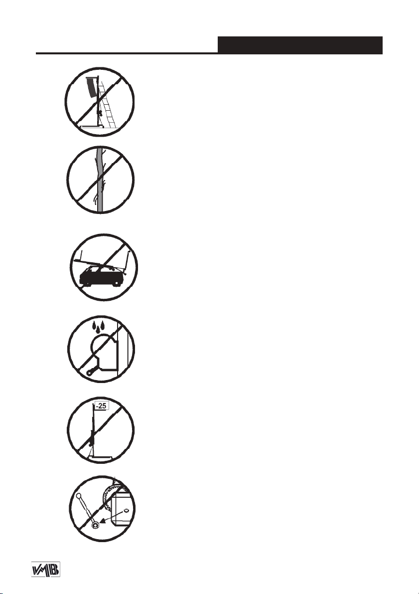
3.11 - Do not use stepladders on the lift or use it as a
support for them.
3.12 - Before using the lift, check the condition of the
cable. The cable should not have broken threads or
show any signs of crushed/flattened areas. NEVER use
faulty cables, always change them if there is any doubt.
Only use VMB steel cables; reference: DIN 3060.
Quality: 180KG/mm and torsion resistant.
3.13 - All sections must be lowered first, and the support
system (SA) must be locked with the catch pawl (R),
before transportation.
3.14 - Do not grease or lubricate the winch’s braking
mechanism. The brake disks have been greased with
a special heat and pressure resistant solution. Other
products should not be used to avoid negative effects
regarding the braking mechanism.
3.15 - The minimum load to avoid problems regarding
the braking mechanism is 25Kg. Without this load the
brake will not work.
3.16 - NEVER take apart the crank of the winch when
the lift is carrying a load or extended.
Depósito legal y copyright 2014. Todos los derechos reservados. 8PRO LIFTS S.L.
Quick operation guide ENGLISH
4. USER INSTRUCTIONS.
4.1 - Place the lift on its working position,
in a firm, flat surface. Remove the exten-
sible bar (EX-034B) from the leg.
4.2 - Firstly, untighten the screw (B) of the
bracket and put the extension bar (EX-
034B) in it, tighten the screw (B) again to
fix the bar. Then remove the safety catch
pawl (R) of the support system (SA) and
untighten the retainer knob (K). Lower the
support system (SA) until you can fix the
safety catch pawl (R) in the required posi-
tion, then tighten the knob (K).
4.3 - THE MAXIMUM LOAD IS 125 Kg
(275 lb). The lift should NEVER be over-
loaded (over 125 Kg). Safety at work is
the most important issue. Untighten the
steel bracket (B) and place the load onto
the lift using an adequate support accor-
ding to the need, use so that the weight
of the load will only elevate in a vertical
direction. The minimum load is 25 Kg.
4.4 - Elevation: Turn the winch crank
clockwise (N1) to lift the tower, the red
ALS lock enable the lift to rise and auto-
matically block the profiles whilst rising,
ensuring that it will never fall.
4.5 - Blocking: Once the system is ele-
vated to its required height gently turn the
handle in a anti-clockwise (N2) direction to
introduce the ALS locks in its correspon-
ding hole and block the profiles. The ALS
lock will take the pressure of the load and
release strain applied on the cable.
Security system ALS
The TE-034 incorporates the patented
security system ALS (Automatic Lock
Security). This VMB red trigger system
automatically blocks the tower in the posi-
tion it is left in. Each section of lift has an
ALS that blocks the section in the unlikely
event of the cable breaking.
4.6 - Lowering: To bring the lift down you
need to first turn the winch handle slightly
clockwise (N1) and at the same time pull
the red ALS lock out. This releases the
blocking systems. Then turn the handle
anti-clockwise (N2), whilst maintaining the
ALS lock pulled out until the profile has
been completely lowered. All red ALS
locks should be pulled out one by one
whilst the handle is turned anti-clockwise
and the profiles are brought down, one by
one.
CAUTION
When two towers are used to elevate a
bridge, down truss or many towers to ele-
vate a structure of any type, it is almost
impossible that two or more people co-or-
3.17 - Only original replacement parts should be used.
ORIGINAL

Depósito legal y copyright 2014. Todos los derechos reservados. 9PRO LIFTS S.L.
Quick operation guide ENGLISH
5.2 - The lift is supplied from the factory
completely greased. However, it is recom-
mended to periodically grease according
to use, the gearing, the axis bearings, the
spiral of the crank, and the sections.
5.3 - All lifts should undergo an annual
technical inspection carried out by an
authorized VMB dealer to check the cer-
tifications and general condition of all the
lift’s elements and security systems invol-
ved in the lift’s use.
5.4 - Only use original spare parts to gua-
rantee a continued security level. The
user loses all rights to warranty if any spa-
re parts other than originals are used or
carries out any modification or alteration
to the towerlift.
5.5 - To request a spare part please in-
dicate the corresponding code which can
be found in this manual together with the
lift’s serial number and year of manufac-
ture.
6. GUARANTEE.
The warranty period for this lift is 2 years
from the date of purchase.
PRO LIFTS S.L. promises, that from the
date of purchase and during the warranty
period to resolve any faults that may oc-
cur, produced through defect material or
fabrication. Damage caused by improper
use, product modification, third party ma-
nipulation or accidental fire are not cove-
red by this warranty.
dinate the winches elevating or lowering
the loads, at exactly the same pace. At a
certain point each tower will be extended
to a height different to that of the others.
For this reason it is necessary that the
structure does not stretch and allows
for these differences. With a rigid fixa-
tion and if the level difference is signifi-
cant, the force generated from the handle
of the winch will deform the structure and
apply a lateral force to the lifts causing
them to break and block.
4.7 - Transport:
For the transport of the tower is necessary
to fold the machine lowering every section
completely, then untighten the screw (B)
of the bracket and remove the extension
bar (EX-034). Once the towerlift is com-
pletely folded, unlock the catch pawl (R)
and untighten the retainer knob (K), then
rise and close the support system (SA) up
to its transport position, then fix the safety
catch pawl (R) and tighten the knob (K).
Attach the extension bar to the leg with
the magnet.
5. MAINTENANCE.
5.1 - Regularly check the state of the ca-
ble. If the cable has broken threads, or if
it shows any signs of crushed/flattened
areas, it should be changed and replaced
immediately with a new one. Do not use
the lift if the cables are in bad condition.
Only use VMB steel cables reference: DIN
3060 torsion resistant.
Depósito legal y copyright 2014. Todos los derechos reservados. 10PRO LIFTS S.L.
Manual de usuario ESPAÑOL
CONTENIDO
1. Introducción.
2. Información técnica.
3. Precauciones de seguridad.
4. Instrucciones de uso.
5. Mantenimiento.
6. Garantía.
1. INTRODUCCIÓN
Estimado cliente: Con el fin de garanti-
zar un funcionamiento seguro y fiable de
la torre elevadora TE-034 por favor, siga
cuidadosamente las instrucciones de este
manual.
Antes de manipular la torre elevadora,
lea las instrucciones completas y tenga
en cuenta la información técnica conte-
nida en este manual. Todos los produc-
tos de VMB se someten a pruebas muy
rigurosas, en condiciones estrictas y son
monitorizados continuamente durante el
proceso de fabricación. Con el fin de ga-
rantizar el correcto funcionamiento y se-
guridad de los elevadores, sólo deben ser
utilizadas piezas originales del fabricante.
Si se utilizan piezas que no sean las origi-
nales del fabricante, o el producto se mo-
difica de alguna manera, el usuario pierde
todos los derechos de garantía.
VMB se reserva el derecho de modificar
las especificaciones y las piezas del pro-
ducto sin previo aviso. El tipo de modelo,
año de producción y el número de serie
deben ser citadas en cualquier consulta o
pedido de piezas de recambio.
2. INFORMACIÓN TÉCNICA
2.1 - Torre elevadora TE-034.
2.2 - Diseñada para levantar sistemas de
trusses e iluminación en sentido vertical a
diferentes alturas.
2.3 - Carga máxima: 125 kg (275 lb).
2.4 - Carga mínima: 25 Kg (55 lb).
2.5 - Altura máxima: 3.8 m (12.5’).
2.6 - Altura plegada: 1,26 m (4.1’).
2.7 - Área de la base: 1.5 x 1.5 m
(4.9’ x 4.9’).
2.8 - Peso de la torre: 21 kg (47 lb).
2.9 - Adaptador: Ø 35 mm
(PSU-034/PSU-06).
2.10 - Material de construcción: Perfiles
de acero DIN 2394.
2.11 - Sistema de tres perfiles telescópi-
cos accionados con cabestrante por ca-
ble de acero y guiado por poleas de acero
acanaladas con cojinetes de bolas.
2.12 - Cabestrante: 450 kg de carga máxi-
ma con freno automático de retención de
la carga. Certificación CE y GS TÜV.
2.13 - Cable: Acero DIN 3060. Calidad de
resistencia a la torsión 180 kg/mm2.
Diámetro del cable: 4 mm.

Depósito legal y copyright 2014. Todos los derechos reservados. 11PRO LIFTS S.L.
Manual de usuario ESPAÑOL
3. PRECAUCIONES DE SEGURIDAD
3.4 - Este elevador NUNCA debe utilizarse para ele-
var una carga que no ha sido correctamente revisada.
Es necesario verificar que la carga está correctamente
apoyada y centrada en el soporte de elevación apro-
piado para que el peso de la carga sólo actúe en una
dirección vertical.
2.14 - Sistema exclusivo ALS (Auto-blo-
queo de seguridad), pat. pen. 200501056.
hed acabado en poliester satinado.
2.15 - Cuatro patas con tapón de plástico.
2.16 - Anclaje del soporte de apoyo de
las patas mediante gatillo de bloqueo y el
pomo retenedor.
2.17 - Protección anti-óxido, imprimación
con pintura de polvo poliester al horno.
2.18 - Barra de extensión (EX-034) inclui-
da, adherida a una pata mediante un po-
tente imán.
3.1 - La torre elevadora TE-034 es una máquna dise-
ñada para la elevación de cargas en dirección vertical.
NUNCA se debe utilizar como plataforma eleavadora
de personas.
3.2 - Situe la torre solo en superficies planas y esta-
bles.
3.3 - La carga máxima indicada en las características
técnicas mostradas en la etiqueta de la torre o en este
manual NO deben ser excedidas.

Depósito legal y copyright 2014. Todos los derechos reservados. 12PRO LIFTS S.L.
Manual de usuario ESPAÑOL
3.6 - NUNCA use el elevador sobre un vehículo o cualquier
superficie móvil.
3.7 - Si existe la posibilidad de vientos fuertes o ráfagas,
coloque el elevador en el suelo con firmeza y fijelo mediante
tirantes tensores. Nunca fije un tirante a un vehículo o cual-
quier otro objeto que se pueda mover.
3.8 - NUNCA mueva el elevador mientras esté cargado. No
es aconsejable llevar a cabo cualquier tipo de movimiento
horizontal, ni tan sólo pequeños ajustes de posición.
3.9 - NUNCA permita que ningún miembro del equipo o
cualquier otra persona se sitúe debajo de la carga en la
zona de operación de las torres elevadoras.
3.10 - Tenga cuidado con todos los obstáculos por encima
de la elevación y su zona de extensión, como cornisas, bal-
cones, letreros luminosos, etc. Es muy importante evitar la
presencia de todo tipo de cables por debajo de la torre ex-
tendida.
3.5 - Comprobar que la torre esta en posición vertical y com-
probar que el soporte de apoyo (SA) esta fijado por el gatillo
de bloqueo (R) y presionado con el pomo retenedor (K).
Depósito legal y copyright 2014. Todos los derechos reservados. 13PRO LIFTS S.L.
Manual de usuario ESPAÑOL
3.12 - Antes de utilizar el elevador, compruebe el estado
del cable. El cable no debe contener hilos rotos o mostrar
signos de áreas aplastadas/aplanadas.
NUNCA use cables defectuosos, siempre debe cambiarlos
si hay alguna duda. Utilice solamente cable de acero VMB
referencia: DIN 3060. Calidad: 180kg/mm y resistente a la
torsión.
3.13 - Todos los tramos deben ser bajados, y el soporte de
apoyo (SA) debe estar bloqueado con el gatillo de bloqueo
(R) y el pomo retenedor (K), antes del transporte.
3.14 - No engrasar ni lubricar el mecanismo de freno del
cabestrante. Los discos de freno vienen engrasados con
una solución especial resistente a la presión y al calor. No
deben utilizarse otros productos, para evitar los efectos
negativos sobre el mecanismo de frenado.
3.15 - La carga mínima para evitar problemas relaciona-
dos con el mecanismo de rotura es 25 kg. Sin esta carga
mínima el freno no funcionará.
3.16 - NUNCA desmontar la manivela del cabrestante
cuando el elevador está soportando una carga o exten-
dido.
3.11 - No usar escaleras encima del elevador ni utilizarlo
como un apoyo para éstas.
Depósito legal y copyright 2014. Todos los derechos reservados. 14PRO LIFTS S.L.
Manual de usuario ESPAÑOL
4. INSTRUCCIONES DE USO.
4.1 - Colocar el elevador sobre una super-
ficie firme y plana de la zona de trabajo,
hecho esto, extraiga la barra de extensión
(EX-034) colocada en una de las patas.
4.2 - Primero, afloje el tornillo de la abra-
zadera (B) y coloque la barra de exten-
sión (EX-034) dentro del perfil, vuelva a
apretar el tornillo (B) para fijar la barra.
Ahora libere el soporte de apoyo (SA)
extrayendo el gatillo de bloqueo (R) y
aflojando el pomo retenedor (K). Baje el
soporte de apoyo (SA) hasta que pueda
fijarlo con el gatillo de bloqueo (R) en la
posición que desee, para terminar aprete
el pomo retenedor (K).
4.3 - LA CARGA MÁXIMA ES 125 kg
(275 lb). El elevador NUNCA debe ser
sobrecargado (más de 125 kg). La Se-
guridad en el Trabajo es el elemento más
importante. Afloje la abrazadera de acero
(B) y coloque la carga en el elevador me-
diante un soporte adecuado según la ne-
cesidad, de modo que el peso de la carga
sólo actúe en dirección vertical.
La carga mínima son 25 kg.
4.4 - Elevación: Gire la manivela del
cabestrante en sentido horario (N1) para
elevar la torre. Los gatillos ALS rojos per-
miten a la torre elevarse y bloquear au-
tomáticamente los tramos mientras esta
subiendo, asegurando que la carga nun-
ca caerá.
4.5 - Bloqueo: Una vez el sistema esta
elevado hasta la altura deseada, gire des-
pacio la manivela en sentido anti-horario
(N2) para introducir los gatillos ALS en su
posición correspondiente y así asegurar
el bloqueo de los perfiles. El gatillo ALS
tomará la presión de la carga y liberará
tensión en el cable.
Sistema de seguridad ALS
La nueva TE-034 incorpora el sistema de
seguridad patentado ALS (bloqueo auto-
mático de seguridad). Este sistema VMB
de gatillo rojo bloquea automáticamente
la torre en la posición que se deja. Cada
tramo de elevación tiene un ALS que blo-
quea el tramo en el caso improbable de
que el cable se rompa.
4.6 - Descenso: Para descender la torre
es necesario, primero girar la manivela
3.17 - Sólo deben ser utilizadas piezas de repuesto
originales de VMB PRO LIFTS S.L.
ORIGINAL
Depósito legal y copyright 2014. Todos los derechos reservados. 15PRO LIFTS S.L.
Manual de usuario ESPAÑOL
rio plegar la máquina bajando todos los
tramos completamente, a continuación
aflojar el tornillo de la abrazadera (B) y
extraer la barra de extensión (EX-034).
Una vez hecho esto, desbloquear el ga-
tillo de bloqueo (R) y aflojar el pomo rete-
nedor (K), hecho esto levantar el soporte
de apoyo (SA) hasta su posición inicial de
transporte, entonces volver a bloquearlo
con el gatillo (R) y el pomo (K).
Para acabar, coloque la barra de exten-
sión (EX-034) en su posición de transpor-
te pegandola a la pata mediante el imán.
5. MANTENIMIENTO
5.1 - Comprobar periódicamente el esta-
do del cable. Si en el cable existen hilos
rotos, o si muestra signos de zonas aplas-
tadas/aplanadas, debe ser sustituido in-
mediatamente por uno nuevo. No use el
elevador si los cables están en mal esta-
do. Utilice solamente cable de acero DIN
3060 resistente a la torsión.
5.2 - La torre elevadora es suministrada
de fábrica completamente engrasada.
Sin embargo, se recomienda un engrase
periódico, según el uso, de las ruedas de
fricción, los cojinetes de eje, la espiral de
la manivela, y los tramos.
RECUERDE: NUNCA engrasar ni lubricar
el mecanismo de freno. No es necesario
engrasar los discos de freno.
del cabrestante ligeramente en sentido
horario (N1) y al mismo tiempo tirar del
ALS rojo para desbloquear (ALS-1), esto
libera el sistema de bloqueo. A continua-
ción, gire la manivela en sentido anti-
horario (N2), mientras desciende el tramo
tirar de los ALS para desbloquear hasta
que el tramo haya sido completamente
bajado. Todos los gatillos rojos ALS de-
ben ser desbloqueados uno a uno mien-
tras giramos la manivela en sentido anti-
horario para así descender los perfiles,
uno a uno.
PRECAUCIÓN
Cuando se utilizan dos torres para elevar
un puente, descender truss o varias torres
para elevar una estructura de cualquier
tipo, es casi imposible que dos o más per-
sonas coordinen los cabrestantes exacta-
mente a la misma velocidad al elevar o
bajar las cargas. En un momento deter-
minado cada torre se elevará a una altura
diferente a la de las demás. Por ello, es
necesario que la estructura no se esti-
re y permita estas diferencias. Con una
fijación rígida y si la diferencia de nivel es
importante, la fuerza generada a partir de
la manivela del cabrestante deformará la
estructura y aplicará una fuerza lateral a
los elevadores provocando su bloqueo y
ruptura.
4.7 - Transporte:
Para el transporte de la torre es necesa-

Depósito legal y copyright 2014. Todos los derechos reservados. 16PRO LIFTS S.L.
Manual de usuario ESPAÑOL
PRO LIFTS S.L. se compromete, que a
partir de la fecha de compra y durante el
período de garantía, a resolver los fallos
que puedan producirse, debidos a mate-
rial defectuoso o fabricación. Los daños
causados por un uso inadecuado, modi-
ficación del producto, la manipulación de
terceros o incendio accidental no están
cubiertos por esta garantía.
Los discos de freno vienen engrasados
con una solución especial resistente a
la presión y al calor. No deben utilizarse
otros productos, para evitar los efectos
negativos sobre el mecanismo de frena-
do.
5.3 - Todos los elevadores deben some-
terse a una inspección técnica anual lle-
vada a cabo por un distribuidor autorizado
VMB para comprobar las certificaciones y
el estado general de todos los elementos
de elevación y sistemas de seguridad que
intervienen en el uso del elevador.
5.4 - Utilice únicamente piezas de repues-
to originales para garantizar el nivel de
seguridad de forma continuada. El usua-
rio pierde todos los derechos de garantía
si las piezas de repuesto utilizadas no son
originales o se utilizan o se lleva a cabo
cualquier modificación o alteración de la
torre elevadora.
5.5 - Para solicitar una pieza de recam-
bio indique el código correspondiente que
se encuentra en este manual junto con el
número de serie de la torre y el año de
fabricación.
6. GARANTÍA
El período de garantía para este elevador
es de 2 años a partir de la fecha de com-
pra.
Depósito legal y copyright 2014. Todos los derechos reservados. 17PRO LIFTS S.L.
TE-034
EX-034/
EX-034B
2043 2091/
2091B
2092/
2092B
2093/
2093B
2094/
2094B
2067/
2067B
2071 2071
2073 2073
2068/
2068B
2072
2072

Depósito legal y copyright 2014. Todos los derechos reservados. 18PRO LIFTS S.L.
TE-034
2032
2032
2032
2044
2056
2056
2056
2036/
2036B
2041
7061
2021
2090 2023
A.3
A
A.1
A.2 A.3
A.3
A.2
2209N
2049 x4
2043
2042/
2042B
A.1
A.2
A.2
Depósito legal y copyright 2014. Todos los derechos reservados. 19PRO LIFTS S.L.
TE-034 B
7078 x3
2152 x3
3232 x3
7160AC
2082
B.1
B.1
2026D
2065/
2065B
2052
2069
2070
2053/
2053B
2074
2044
2047
7061
2035
7061
2047
2038
7078
7078
7078
2070 7078 2052 7078
2069 7078

Depósito legal y copyright 2014. Todos los derechos reservados. 20PRO LIFTS S.L.
TE-034
C
C.3
C.2
C.1
C.1
C.2
C.3
6406
7078 2152 3232
2039
2022
2024
2025
3233
3233
6401
2082
Table of contents
Languages:
Other PRO LIFTS Lifting System manuals

PRO LIFTS
PRO LIFTS VMB TL-075 Instruction Manual

PRO LIFTS
PRO LIFTS VMB TL-A300 Instruction Manual

PRO LIFTS
PRO LIFTS VMB TL-054 Instruction Manual

PRO LIFTS
PRO LIFTS VMB TE-064 Instruction Manual

PRO LIFTS
PRO LIFTS VMB TE-064 Instruction Manual

PRO LIFTS
PRO LIFTS VMB TE-076 Instruction Manual

PRO LIFTS
PRO LIFTS VMB TE-071 User manual

PRO LIFTS
PRO LIFTS VMB TL-A500 Instruction Manual

PRO LIFTS
PRO LIFTS VMB TE-074 Instruction Manual

PRO LIFTS
PRO LIFTS VMB TL-A400/8 Instruction Manual


