Böcker BOY User manual

D
F
GB
Betriebsanleitung
Manuel de service
Operating Instructions
BOY
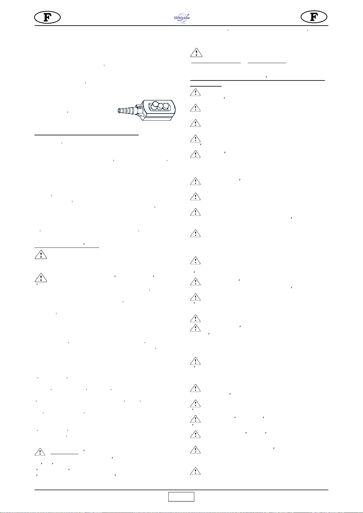
Vor Beginn aller Arbeiten Betriebsanleitung
lesen!
Avant de mettre l'appareil en service lire
attentivement le manuel de service !
Every operator, before he places the device in
service, must read the operating manual!
Dok.Nr. / Document no.: 92016700068
3225503-R2

Boy
© Böcker Maschinenwerke GmbH
Lippestr. 69-73
D-59368 Werne
Tel.: +49 (0) 2389 7989-0
Fax: +49 (0) 2389 7989-9000
E-Mail: info@boecker-group.com
Internet: www.boecker-group.com

Boy
Zuordnung dieser Anleitung
Die vorliegende Montage- und Betriebsanleitung ...
Doku-Nr.: 92016700068
Version 21072010
… ist gültig für:
Typ: Boy
Affectation du présent manuel de service
Le présent manuel de service et de montage ...
Document no.: 92016700068
Version 21072010
… est valable pour :
Modèle : Boy
Assignment of these operating Instructions
This assembly and operating instruction…
Document no.: 92016700068
Version 21072010
… applies to:
Type: Boy

Boy
2
WASSERWAAGE
NIVEAU
WATER LEVEL
Lesen Sie die mit diesem Symbol bezeichneten Abschnitte mit besonderer Aufmerksamkeit:
Il faut prêter une attention toute particulière aux notes précédées de ce symbole:
Special attention must be given to warnings with this symbol:
Abb. 1
1
STAHLSEIL
CABLE D'ACIER
STEEL ROPE
2
HAKEN
CROCHET
HOOK
3
SEILTROMMEL
TAMBOUR
DRUM
4
BREMSMOTOR
MOTEUR ELECTRIQUE
AUTOFREINANT
ELECTRIC BRAKE MOTOR
5
GEHÄUSEDECKEL
TABLEAU ELECTRIQUE
ELECTRIC PANEL
6AUSZIEHBAREN ARM
BRAS EXTENSIBLE
EXTENDABLE ARM
7SCHWENKBARE TRÄGERSTRUKTUR CHÂSSIS PORTANT TOURNANT ROTARY SUPPORT FRAME
8ARRETIERUNGS HEBEL MIT
SCHRAUBE
POIGNEE DE BLOCAGE LOCKING HANDLE
9
ENDSCHALTERHEBEL
LEVIER FIN DE COURSE LIMIT SWITCH LEVER
10
GEGENGEWICHT
CONTREPOIDS
COUNTERWEIGHT
11
ARRETIERHEBEL DER STRUKTUR LEVIER BLOCAGE CHÂSSIS FRAME LOCKING LEVER
12
DREHZAPFEN
AXE DE SOUTIEN
SUPPORT PIN
13
SPLINT
GOUPILLE
SPLIT PIN
14
GETRIIEBEDECKELDICHTUNG
REDUCTEUR
GEAR BOX
15
HÄNGETASTER
BOITE Á BOUTONS PENDANT CONTROL
16
WÄRMESCHALTER
INTERR. THERMIQUE THERMAL OVERLOAD
17
HEBEL ENDSCHALTER LEVIER DE DESCENTE DOWN POSITION LEVER
TECHNISCHE DATEN DONNEES TECHNIQUES TECHNICAL DATA Boy 1140625
Max Tragfähigkeit Débit maxi. Max capacity
kg
200
Hubgeschwindigkeit Vitesse de levage Lifting speed m / 1'
19
Max. Hubhöhe Hauteur maxi. de travail Max working height m
30
Spannung
Alimentation Nom. voltage V / Hz 230 / 50
Motorleistung Puissance moteur Motor power
Kw
0.75
Motordrehzahl
Tours moteur
R.P.M.
n° / 1'
1.380
Stromaufnahme
Absorption Nom. current A
7,2
Betriebsart Type de service Duty type
S3
50 %
Schallpegel der verschiedenen
-- LwA (EN ISO 3744)
Niveau d'emission sonore --
LwA (EN ISO 3744)
Noise emission level -- LwA
(EN ISO 3744)
dB
79
Gemessenem
schalleistungspegel -- LpA --
1,5 m
Niveau de puissance sonore --
LpA -- 1,5 m
Level of noise pressure -- LpA -
- 1,5m
dB
<70
Maschinengewicht Poids de la machine Machine weight
kg
46
Abmessungen mit Verpackung Encombrement pour
l'emballage
Packing dimensions
mm
820x350x500
Konstruktionsnormen Normes de projet Design standards
FEM 1.001, ISO 4301-4308-2408, UNI 7670-9466, EN 60204-1, EN 60204-32,
EN 60034-1, ISO 6336-1/-2
Fig. 1

3
Boy
Verehrter Kunde,
herzlichen Glückwunsch zum Erwerb Ihrer Steinweg-Böcker-
Baumaschinen GmbH
, die das Ergebnis einer langjährigen Erfahrung
und eine extrem zuverlässige Maschine mit innovativen technischen
Lösungen ist.
-
SICHERHEIT BEI DER ARBEIT: Aus Sicherheitsgründen
sollten die folgenden Anleitungen unbedingt sorgfältig
durchgelesen werden.
Dieses Anleitungsheft für GEBRAUCH UND WARTUNG muß vom
Baustellenleiter aufbewahrt werden und stets für eventuelles
Nachschlagen zur Verfügung stehen. Das Anleitungsheft ist Teil der
Maschine und muß bis zum Verschrotten derselben für späteres
Nachlesen (EN ISO 12100-2) aufbewahrt werden. Im Falle des
Verlustes oder der Beschädigung kann vom Hersteller der Maschine
ein neues Exemplar angefordert werden.
Das Anleitungsheft enthält wichtige Hinweise zu
Baustellenvorbereitung, Installation, Einsatz, Wartung und
Ersatzteilbestellung.
Monteur und Anwender sollten jedoch in jedem Fall über ausreichende
Erfahrung und Kenntnis der Maschine verfügen.
Für die Sicherheit der Bedienungsperson, die zuverlässige Funktion
und lange Haltbarkeit der Maschine müssen die Anleitungen dieses
Heftes und die einschlägigen Normen für die Sicherheit und
Unfallverhütung am Arbeitsplatz (Gebrauch spezieller Schuhe und
Kleidung, Schutzhelme, Sicherheitsgurte, Schutzgeländer, usw.)
unbedingt befolgt werden.
-
Die Veränderung der Metallstruktur oder der
Ausrüstung der Maschine ist verboten.
Falls die Gesetze über den Einsatz von Hebezeug nicht
eingehalten werden, und zwar im besonderen bei ungeeignetem
Einsatz, falscher Zuführung, mangelnder Wartung, nicht
autorisierten Änderungen, Fremdeingriffen und/oder
Beschädigungen, sowie teilweiser oder vollkommener
Nichteinhaltung der in diesem Handbuch enthaltenen
Anleitungen, übernimmt die Firma Steinweg-Böcker-
Baumaschinen GmbH keinerlei Haftung.
-
Steinweg-Böcker-Baumaschinen GmbH behält sich
vor, die Charakteristiken der Seilwinde und/oder den Inhalt
dieses Handbuchs zu ändern, ohne auch das Gerät und/oder
die früheren Handbücher zu aktualisieren.
1. ALLGEMEINE BESCHREIBUNG
-
Hinweis:
Der Einsatz eines Hebezeugs erfordert viel
Sorgfalt und Sachkenntnis und die Bedienung darf folglich
nur fachlich ausgebildetem oder entsprechend geschultem
Personal anvertraut werden.
-
1) Die Maschine wurde für das Heben von Material und
den Einsatz auf Baustellen konstruiert.
-
2) Der Transport von Personen und/oder Tieren ist
ausdrücklich untersagt!
-
3) Das Gerät darf nicht an Orten mit Explosions- oder
Feuergefahr oder mit unterirdischen Grabungen eingesetzt
werden.
Das Gerät besteht im wesentlichen aus den folgenden Komponenten
(Abb.1):
- An der Welle des Untersetzungsgetriebes montierte Trommel (Bez.3),
ein Metallseil (Bez.1), ein Haken (Bez.2) und ein Gegengewicht
(Bez.10).
- Getriebemotor, bestehend aus einem selbstbremsenden E-Motor
(Bez.4) und einem Untersetzungsgetriebe mit Zahnrädern in Ölbad
(Bez.14).
- Elektrik (Bez.5).
- Schalthebel Hub-Endschalter (Bez.9).
- Schalthebel Senkungs-Endschalter (Bez.17).
- Schwenkbare Tragestruktur (Bez.7) mit ausziehbarem Arm (Bez.6),
Arretiergriff (Bez.8), Struktur-Arretierhebel (Bez.11).
- Wärmeschalter (16), der die Seilwinde anhält, sobald der Strom den
Nennwert übersteigt (für das Rückstellen diesen Schalter drücken).
- Die Seilwinde verfügt über 3 Arten von Bedienfeldern (Bez.15):
- Bedienfeld zu 1,5 m mit direkter Steuerung,
- Bedienfeld zu 30 m mit Niedrigspannung 24 V.
2. SEILWINDEN-HALTESTRUKTUREN
Die Struktur, an der die
Seilwinde befestigt
wird, muß in der Lage
sein den während
dem Einsatz
entstehenden
Belastungen der
Abb.2 standzuhalten.
Die Kraft von 400N ist
senkrecht zu der
Kraft 7.900 N. Da die
Winde auf den
Halteknäufen drehen
kann, müssen diese
Kräfte in allen
potentiellen Positionen
der Winde geprüft werden.
Die Firma Steinweg-Böcker-Baumaschinen GmbH verfügt über
eine breite Auswahl von Haltestrukturen für die unterschiedlichen
Anforderungen der Baustelle, die in den Abbildungen 7-8-9-10-11
gezeigt werden, und die so beschaffen sind, daß diese Belastungen
auf geeignete Weise auf die Strukturen übertragen werden.
-
ACHTUNG
Die diesem Anleitungsheft beigelegte CE-
Konformitätserklärung ist nur dann gültig, wenn
ausschließlich Konstruktionskomponenten von Steinweg-
Böcker-Baumaschinen GmbH (Seilwinde und
Haltestruktur) verwendet werden.
Sofern diese Bedingungen nicht eingehalten werden, gilt ist
diese Erklärung nur für die Seilwinde.
Der Installateur ist verpflichtet, nach der Prüfung aller in der
Maschinenrichtlinie 2006/42/EG enthaltenen Anforderungen
eine neue EG-Konformitätserklärung auszustellen.
Die Kräfte, die an den Auflagen der Stützen aufgeführt sind,
müssen bei der statischen Berechnung der Tragestrukturen
(Gerüste, Bühnen, Decken, usw.) durch einen kompetenten
Techniker berücksichtigt werden.
Falls die Seilwinde an einem Gerüst befestigt wird, muß dieses
entsprechend verstrebt werden (siehe Abbildung 12).
Bei der Installation der verschiedenen Haltestrukturen müssen die
jeweiligen Anleitungen befolgt werden.
Falls Haltestrukturen mit von jenen der Seilwinde abweichender
Tragefähigkeit verwendet werden, muß an dem installierten Gerät gut
sichtbar die zulässige Tragefähigkeit des kritischsten Elementes des
Systems angebracht werden.
2.1 VORBEREITUNG DES ARBEITSPLATZES
-
Die Zugangsseite auf die Last an den Stockwerken
muß mit einer mindestens 1 m hohen Brüstung und
Fußbarriere ausgerüstet werden.
- Sicherstellen, daß der Arbeitshub auf der gesamten Länge frei von
Behinderungen ist und dafür Sorge tragen, daß sich niemand aus
den dazwischen liegenden Stockwerken hinauslehnen kann.
- Den unteren Ladebereich absperren, damit sich während dem
Hebevorgang dort niemand aufhalten kann.
3. MONTAGE (Abb.1)
1) Die Montage und der Einsatz der Seilwinde erfordern fachlich
ausgebildetes oder entsprechend geschultes Personal.
Wegen des hohen Gewichtes der Seilwinde muß eine
ausreichende Zahl von Personen eingesetzt werden, damit
sich während dem Transport und der Installation keine
gefährlichen Situationen ergeben können.
2) Die max. Arbeitshöhe (30 m) entspricht der Position des
Getriebemotors, die jener des oberen Zapfens der Halterung entspricht.
3) Die Tragestruktur an der Gebäudestruktur befestigen, die vertikale
Ausfluchtung der Haltezapfen (Bez.12) prüfen, den Arretierhebel
(Bez.11) anheben, die Buchsen der Tragestruktur an den Zapfen
einsetzen und den Sicherungssplint (Bez.13) einsetzen.
4) Den ausziehbaren Arm (Bez. 6) bis zur Position der
Mindestausdehnung an der Struktur montieren und den Griff
mit Unterlegscheibe über die Öse in das Gewindeloch (Bez. 7)
an den Zapfen einschrauben.
5)
Mit einer auf die obere Platte der Seiltrommel aufgelegten
Wasserwaage kontrollieren, ob der Elevator perfekt eben ist
(Abb. 1)
.
6)
Der Teleskoparm gestattet, ausgehend von den Zapfenachsen,
einen Hubweg zwischen 720 und 1.120 mm.
Abb. 2
URSPRÜNGLICHER TEXT
4
Boy
7) Falls auf einer Brückenstruktur montiert wird, muß der
ausziehbare Arm (Bez. 6) mittels der vorhandenen Bohrungen
(Bez. Abb.12) mit den mitgelieferten selbstsperrenden Schrauben
und Muttern befestigt werden.
8)
Das Bedienfeld mit direkter Steuerung (zu 1,5 oder 5 m) mit Hilfe des
speziellen Steckverbinders an die Schalttafel (5)
und den
Karabinerhaken des Stahlkabels an den hierfür vorgesehenen
Ring auf dem Schaltpult befestigen, um Zugeinwirkungen auf
das Stromkabel zu vermeiden.
Bei Steuerung mit 24V-Niedrigspannung muß die Schalttafel mit dem
Bügel an der Tragestruktur befestigt und der Steckverbinder an die
Schalttafel (5) angeschlossen werden.
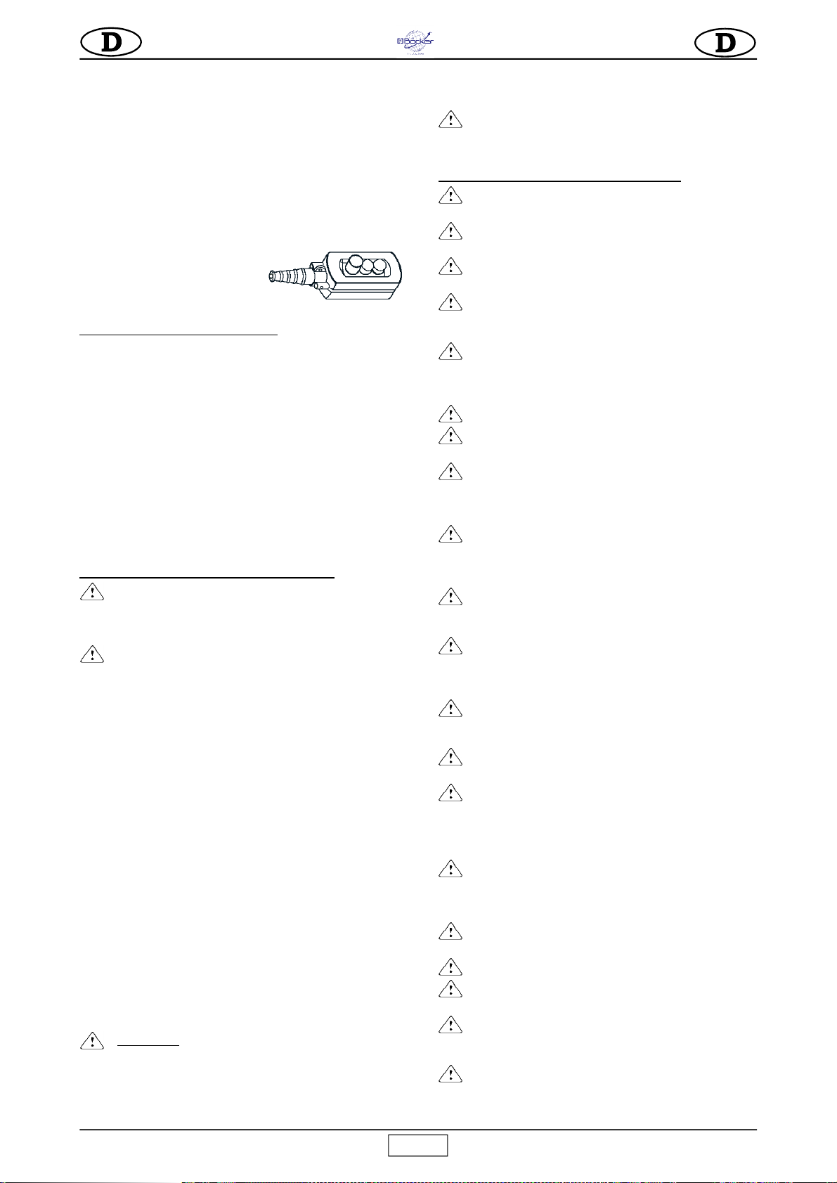
Alle Steuergeräte sind mit einem
Bedienfeld mit drei Tasten (Abb.3)
ausgestattet:
schwarz = Abwärts, weiß = Aufwärts,
Rot = Notstop.
9) Den Haken befreien.
4. ANSCHLUSS AN DAS STROMNETZ
- Kontrollieren, ob die Versorgungsspannung den Daten des
Typenschildes der Maschine entspricht.
- Außerdem kontrollieren, ob die Leitungsspannung bei voll belastet
funktionierender Seilwinde zwischen 210V und 235V beträgt.
- Die Stromleitung muß gegen Überlastung geschützt und mit einem
Differentialschutz ausgestattet sein, und der Erdleiter muß denselben
Querschnitt wie der Leiter aufweisen. Die Bemessung der Leiter muß
dem Anlaufstrom und der Leitungslänge entsprechen, damit
übermäßiger Spannungsabfall vermieden wird (Bez. Tab.1).
Auf Trommeln aufgewickelte Verlängerungskabel vermeiden.
- Der Versorgungsleiter muß für häufige Bewegungen geeignet und
mit einem abriebfesten Mantel ausgestattet sein (z.B. H07RN-F).
- Den Stecker der Maschine an eine CEE-Steckdose zu 16 Ampere mit
Schutzgrad IP67 anschließen und mit der mechanischen Zwinge
sichern.
- Damit ist die Seilwinde für den ersten Probelauf bereit.
5. ANLEITUNGEN FÜR DIE ABNAHMEPRÜFUNG
-
Achtung! Diese Prüfung muß durch kompetentes
Fachpersonal und unter Anwendung der
erforderlichen Vorsichtsmaßnahmen für die Sicherheit
des Personals erfolgen.
-
Achtung: die Abnahmeprüfung muß in jedem Fall vor
dem Einsatz der Seilwinde durchgeführt werden.
Vor Beginn der Prüfung sorgfältig kontrollieren, ob alle
Installationsarbeiten korrekt ausgeführt wurden.
1) Das Seil durch Betätigen der Abwärtstaste leer bis zum unteren
Ladebereich absenken und prüfen, ob am Endanschlag mindestens
drei Wicklungen auf der Trommel verblieben sind.
2)
Leerzyklus-Probe
. Eine geringe Last (20 kg) anwenden und
durch Ausführung eines kompletten Auf- und Abwärtslaufs die korrekte
Funktion der Maschine kontrollieren.
Die Aufwärts-, Abwärtstaste und den Notstop-Schalter, das Auslösen
des oberen Endschalters und das korrekte Aufwickeln des Kabels
auf der Trommel, sowie das Auslösen der Motorbremse ausprobieren.
3)
Belastungsprobe
. Während diesem Versuch muß die maximale
Traglast der Seilwinde angewandt werden. Einen kompletten Aufwärts-
und Abwärtslauf ausführen, um die Verankerungen der Seilwinde
und der Bremsvorrichtung des Elektromotors zu kontrollieren.
Nach der Probe muß kontrolliert werden, ob an den Strukturen eventuelle
Senkungen oder Setzungen vorhanden sind, indem die horizontale
Ausfluchtung der Trommel nachgeprüft wird (unter Verwendung einer
Wasserwaage, siehe Abb.1).
4)
Der Seilwinde ist mit einer Sicherheitsvorrichtung ausgestattet,
welche den Hub der Maschine am höchsten Punkt (Bez.9) und bei
komplettem Abwickeln des Kabels (Bez.17) anhält, wodurch die Umkehr
der Aufwicklung auf die Trommel vermieden wird.
Es empfiehlt sich jedoch deren Auslösen durch rechtzeitiges Loslassen
der entsprechenden Taste und folgliches Anhalten der Maschine zu
vermeiden.
- ACHTUNG !
Der Endschalter kann ausgelöst werden,
wenn die Nutzhöhe ungeeignet ist oder andere Probleme
vorliegen, welche die Leistungsfähigkeit des Elevatores
beeinträchtigen können. Wenn er ausgelöst wurde, müssen
Installation und die Komponenten des Elevators (Seil,
Trommel, Welle, Seil, usw.) kontrolliert werden.
Nach Abschluß der Probe muß das Datum, die Prüfung der Installation,
komplett mit Unterschrift und eventuellen Anmerkungen in das
Prüfungsprotokoll (Tab.2) eingetragen werden.
-
Das beschriebene Prüfverfahren, komplett mit
Leerzyklus-Probe 2) und Belastungsprobe 3) muß bei jeder
neuen Installation der Maschine durchgeführt werden.
6. GEBRAUCHS- UND SICHERHEITSHINWEISE
-
1) Die angehobenen Lasten dürfen keinesfalls die
Tragfähigkeit der Seilwinde überschreiten.
-
2) Der Aufenthalt unter der hängenden Last ist
strengstens verboten.
-
3) Keine am Boden verankerten Lasten anheben
(beispielsweise in die Erde eingelassene Pfähle, Plinthen usw.).
-
4) Vor jeder Beförderung die einwandfreie
Befestigung der Last am Haken prüfen und immer die
Sicherung schließen (Bez. 6, Abb. 4.1).
-
5) Eventuell für die Befestigung der Last am Haken
erforderliches Zubehör (Riemen, Seile, Gurte, usw.) muss
geprüft und bescheinigt sein. Das Gewicht dieser
Zubehörteile muss von der Höchstlast abgezogen werden.
- 6) Während der Hubfahrt dürfen keine Lastteile hervorstehen.
-
7) Die Last darf erst von der Seilwinde gelöst
werden, wenn sie stabil aufliegt.
-
8) Es dürfen weder hängende Lasten ruckartig
gelöst werden noch darf die Verzurrung aufgeschnitten
werden, um eine Last abzuladen, da dies eine elastische
Gegenreaktion auf die gesamte Struktur bewirkt.
-
9) Während des Betriebs weder die Hände noch
andere Körperteile an die Trommel annähern, um
schwerwiegende Verletzungen durch ein Verfangen im
sich aufwickelnden Seil zu verhindern.
-
10) Am Endschalterhebel besteht Klemmgefahr:
Während des Betriebs weder die Hände noch andere
Körperteile in die Nähe des Gegengewichts bringen.
-
11) Die Maschine nicht bei ungünstigen
Witterungsverhältnissen (starker Wind oder Gewitter)
in Betrieb nehmen, weil die Last in einem solchen Fall
nicht ausreichend geführt wird.
-
12) Die Bedienungsposition und die Beleuchtung
muss entlang des gesamten Hubwegs freie Sicht auf die
Last ermöglichen.
-
13) Sicherstellen, dass alle Schutzvorrichtungen
korrekt positioniert sind.
-
14) Während des Gebrauchs kontrollieren, ob sich
das Kabel korrekt Windung an Windung und ohne
Lockerungen oder Überlagerungen aufwickelt, die das
Kabel beschädigen könnten. Andernfalls das Kabel wieder
abwickeln, gespannt halten und korrekt aufwickeln.
-
15) Sicherstellen, dass der Arbeitshub auf der
gesamten Länge frei von Behinderungen ist und dafür
Sorge tragen, dass sich niemand aus den dazwischen
liegenden Stockwerken hinauslehnen kann.
-
16) Den unteren Ladebereich abgrenzen, damit sich
niemand unter der angehobenen Last aufhalten kann.
-
17) Kinder von der Seilwinde fern halten.
-
18) Während der Nichtbenutzung der Seilwinde
muss der Zugriff durch Unbefugte verhindert werden.
-
19) Der Einsatz der Seilwinde für schräge
Beförderungsstrecken (mehr als 5° im Vergleich zur
Senkrechten) ist untersagt.
-
20) Die Seilwinde darf auf keinen Fall durch Ziehen
am Bedienfeld auf den Zapfen geschwenkt werden,
Abb. 3
5
Boy
hierzu muss die Struktur manuell gedreht werden.
-
21) Schwebende Lasten nicht unbeaufsichtigt lassen,
sondern heben oder absenken und abladen.
-
22) Die Last darf sich während der Hub- und Senkfahrt
nicht drehen, da andernfalls das Seil brechen könnte.
-
23) Vor dem Verlassen der Baustelle und der
Seilwinde die Last abnehmen, das Seil ganz auf die
Trommel aufwickeln und den Netzstecker ziehen.
-
24) Beim Heben oder Senken einer Last diesen Vorgang
so steuern, daß gefährliche seitliche und vertikale
Bewegungen so weit wie möglich vermieden werden.
Jedesmal wenn die Arbeit nach einer längeren Arbeitspause (z.B.
Nachtruhe) wieder aufgenommen wird, muß die Seilwinde erneut
kontrolliert werden, indem eine Leerzyklus-Probe durchgeführt werden
(gemäß der unter Punkt 2, Kapitel 5 angeführten Anweisungen).
7. PRÜFUNGEN UND WARTUNG
-
Achtung! Alle Wartungsarbeiten müssen bei
stillstehender Maschine, ohne Last und bei abgehängter
Stromversorgung erfolgen.
- Reparaturen müssen von Fachpersonal oder in den
STEINWEG
-
Kundendienst-Zentren ausgeführt werden.
- Verwenden Sie ausschließlich Original-Ersatzteile.
-
Alle 6-7 Tage die Leistungsfähigkeit der Bremse des E-
Motors prüfen.
-
Alle Aufschriften und Schilder an der Maschine stets
perfekt leserlich halten.
-
Schmutzablagerungen auf der Maschine müssen
immer sofort entfernt werden.
-
Die Funktion der Endschalter für Hub stets effizient
halten und vor jeder Arbeitsschicht kontrollieren.
-
Vor jedem Einsatz der Maschine systematisch den
Zustand des Stromkabels untersuchen, das in der
Zwischenzeit unwissentlich und/oder unbewußt beschädigt
worden sein könnte.
7.1 STAHLSEIL
Verwenden Sie ausschließlich neue Seile mit den nachstehend
vorgeschriebenen Merkmalen, sowie mit Konformitäts- und
Identifizierung-Zeugnis.
- Außendurchmesser
5 mm
- Zusammensetzung 133 drehgesicherte Drähte
- Festigkeit Elementärdraht
1.960 N/mm
2
- Min. Bruchbelastung
16 kN
- Länge
31 m
- Oberflächenbehandlung gefettet, verzinkt
- Der
STEINWEG
-Bestellcode ist in der Ersatzteil-Tabelle aufgeführt.
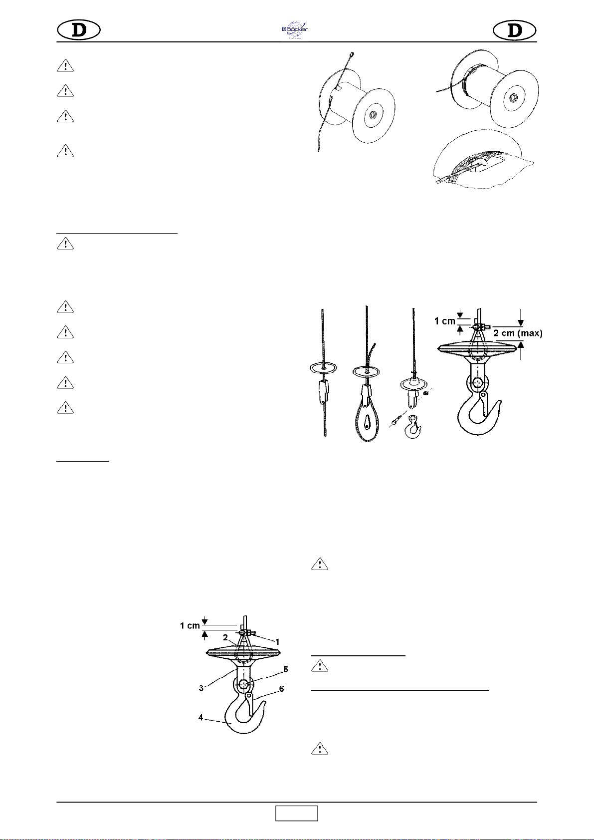
7.1.1 WECHSELN DES SEILS (Abb.4)
Das Seil muß stets von einem kompetenten Wartungstechniker
ausgewechselt werden.
Den Haken (Bez.4) durch Aufschrauben der Mutterschraube (Bez.5)
ausbauen (Abb. 4.1).
Die Klammer (Bez.1) ausbauen, den
Keil (Bez.2) andrücken und das Seil
aus dem Seilblock (Bez.3) ziehen.
Die Trommel ist mit einer Vorrichtung
ausgestattet, die dafür sorgt, daß auch
bei vollkommen abgewickeltem Seil
stets zwei ganze Seilwindungen
aufgewickelt bleiben, damit der
Befstigungspunkt des Seils nicht
forciert wird.
Wenn das Seil gewechselt wird, muß
das neue Seil so montiert werden, daß
diese Bedingung gegeben ist.
Das Seil vollkommen abwickeln. Über das spezielle Loch und die Öse
aus dem Trommelinnern ziehen.
Das neue Seil in das Loch einführen und durch die Öse des
Trommelzylinders führen; die Klemme am Ende befestigen, wobei
zirka 1 cm Seil frei bleiben soll (Abb. 4.2). Nun das Seil ziehen, bis die
Klemme an der Innenwand der
Trommel anliegt.
Zwei vollständige Windungen
aufwickeln, wobei das Seil
ständig in Kontakt mit der Trommel sein muß (Abb.4.3).
Bei der zweiten Windung das Seil unter dem Haken im Innern der
Trommelöse durchführen (Abb.4.4).
Das Seil anziehen und kontrollieren, ob es ganz am Zylinder anliegt.
Das Seil Windung an Windung in aufeinanderfolgenden Lagen korrekt
aufwickeln.
Das Stahlseil in das Gegengewicht und den Seilblock einführen
(Abb.4.5).
Das Seil erneut durch den Seilblock und das Gegengewicht führen.
Den Keil zwischen Seilblock und Stahlseil einführen.
Das Seil anziehen, bis alle Komponenten untereinander angezogen
sind. Dann das Seil mit einer U-förmigen Klammer blockieren, wobei
der flache Teil in Kontakt mit dem Zugseil bleiben muß.
Anschließend den Haken am Seilblock montieren und mit der
selbstsperrenden Schraube und Mutter sichern.
Kontrollieren, ob der obere Hub-Enschalter funktioniert, wenn das
Gegengewicht gegen den Hebel stößt.
Die unter Absatz 5 beschriebene Belastungsprobe durchführen und
den erfolgten Wechsel in die Tab. 2 eintragen.
7.1.2 REGELMÄSSIGE KONTROLLEN
-
Täglich und jedesmal wenn anomale Belastungen
auftreten (Verdrillungen, starkes Sperren der
Windungen, Knicke oder Abrieb) eine Sichtkontrolle des
Seils durchführen.
Im Falle der in der Abb.13 aufgeführten Mängel muß das Seil
ersetzt werden.
Alle drei Monate muß das gesamte Seil, und zwar besonders die
Enden, sorgfältig kontrolliert werden. Das Prüfergebnis ist in das For-
mular des Anleitungsheftes Tab.2 einzutragen, das vom
Baustellenleiter verwahrt
werden muß.
-
Das Seil mindestens einmal pro Jahr erneuern.
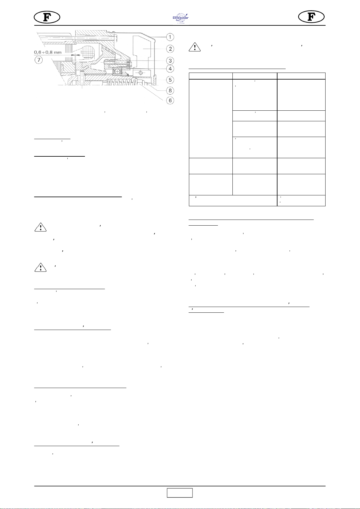
7.2 EINSTELLUNG DER MOTORBREMSE (Abb.5)
Die Bremse des Elektromotors spricht bei Ausfall der
Motorstromversorgung an.
Falls sich die Bremskraft verringern sollte, muss die Vorrichtung
vom zuständigen Wartungstechniker kontrolliert und bei Bedarf
reguliert werden.
-
Achtung! Vor Eingriffen an der Bremse stets
sicherstellen, dass die Last abgenommen, der
Netzstecker gezogen und der Motor kalt ist.
7.2.1. Einstellung der Bremse
Den Verschluss 5 der Lüfterradabdeckung 1 entfernen.
Abb. 4.1
Abb. 4.2 Abb. 4.3
Abb. 4.4
Abb. 4.5

6
Boy
Steigerung der Bremswirkung:
Die selbstsichernde Mutter 6
langsam gegen den Uhrzeigersinn drehen und prüfen, ob die
Bremse während der Senkfahrt ausgelöst wird.
Reduzierung der Bremswirkung:
Mutter 6 im Uhrzeigersinn drehen.
7.2.2. Regulierung des Spalts
Falls die Bremse blockiert oder abgenutzt ist, muss der Spalt
folgendermaßen eingestellt werden.
Die Lüfterabdeckung 1 abnehmen und den Lüfter 2 demontieren.
Die drei Inbusschrauben 3 lockern.
Bremse blockiert:
Nut 4 im Uhrzeigersinn drehen, um den Spalt
7 zu vergrößern und die Bremse zu entsperren (Abstand 0,6-
0,8 mm).
Bremse abgenutzt
: Nut 4 gegen den Uhrzeigersinn drehen, um
den Spalt zu verkleinern (Abstand 0,6-0,8 mm).
Die drei Inbusschrauben 3 vorschriftsmäßig arretieren und
Lüfter samt Abdeckung montieren.
Die Bremswirkung nach ausgeführter Einstellung mehrmals mit
voller Last prüfen.
7.3 SCHMIEREN DES GETRIEBEMOTORS
- Der Getriebemotor darf kein Öl verlieren. Auffällige Ölverluste können
auf Beschädigungen der Aluminium-Struktur hinweisen. In diesem Fall
muß das Gehäuse sofort abgedichtet oder gewechselt werden.
-
Vor jedem Gebrauch über das Schauglas den Ölstand
des Getriebemotors kontrollieren und eventuell auffüllen. Das
Öl muß zirka alle 2000 Betriebsstunden gewechselt werden.
Verwenden Sie zu diesem Zweck Getriebeöl mit Viskosität VG
460 bei 40 °C (SAE 90-140).
-
Altöl ist Sondermüll, der vorschriftsmäßig entsorgt
werden muß.
7.4 ELEKTRIK
Die Unversehrtheit der isolierenden Hülle des Bedienfeldes kontrollieren
und diese im Falle der mangelhaften Dichtigkeit durch ein
STEINWEG
Original-Ersatzteil ersetzen. Sicherstellen, daß die Stahllitze, die das
Bedienfeld mit der Schalttafel verbindet, kürzer als das Stromkabel ist,
damit dieses nicht gezogen wird.
8. DEMONTAGE DER SEILWINDE
Jede Art von Last vom Haken der Seilwinde nehmen.
Das Metallseil vollkommen auf die Trommel aufwickeln. Die
Stromversorgung abhängen.
Den Splint am Haltezapfen entfernen und die schwenkbare
Tragestruktur ausbauen.
Bei Verwendung von Brücken den Hubwagen zunächst aus den
Führungen nehmen, von der Seilwinde ausbauen und erst dann die
Ballaste abnehmen..
9. TRANSPORT UND STILLEGUNG
- Lassen Sie die installierte Seilwinde niemals unbeaufsichtigt stehen,
ohne zuvor die Stromversorgung abzuhängen und das Seil ganz auf
die Trommel aufzuwickeln.
Falls die Maschine längere Zeit eingelagert werden soll, muß sie
unbedingt gegen Witterungseinflüsse geschützt werden.
- Während dem Transport müssen die verschiedenen Maschinenteile
gegen Stöße und Einklemmen geschützt werden, weil sonst die
Funktionalität und die mechanische Festigkeit gefährdet werden.
10. VERSCHROTTEN DER SEILWINDE
Bei der Verschrottung der einmal ausrangierten Seilwinde sollten
wenigstens die folgenden Phasen eingehalten werden:
a) das Öl über den speziellen Stopfen ablassen;
b) Die verschiedenen Plastikteile und Elektrokomponenten (Kabel,
Bedienfeld, usw.) trennen;
STÖRUNGEN
URSACHEN
ABHILFEN
Beim Drücken der
Funktionstasten (Aufwärts
oder Abwärtslauf)
funktioniert die Maschine
nicht
Die Notschalter ist
gedrückt
Den Notschalter
ausschalten
Die Maschine erhält
keine Spannung
Die Leitung
kontrollieren
Stecker nicht fest in die
Dose eingestekt
Richtige Verbindung
herstellen
Magnetthermoschlter
der Hauptschalttafel hat
geschaltet
Magnetthermoschalter
wieder einschalten
Abwärtshub, jedoch kein
Aufwärtshub
Hub-Endschalter defekt
Reparatureingriff
vornehmen
Schwergängiges
horizontales Gleiten der
Teleskopverlängerun.
Arretiergriff zu stark
angezogen.
Lockern.
Bleibt der Defekt weiter bestehen
Kundendienst rufen
STEINWEG
c) die Metallkomponenten nach Art des Metalls sortieren (Stahl,
Aluminium, usw.).
Die auf diese Weise sortierten Teile vorschriftsmäßig entsorgen.
-
Die Komponenten nicht unkontrolliert wegwerfen,
da sie sich entzünden können und die Umwelt belasten.
11. STÖRUNGEN/URSACHEN/ABHILFEN
12. AUSFALL DER MASCHINE BEI SCHWEBENDER LAST
- Sofern möglich die Last von der entsprechenden Etage aus
abnehmen, die Seilwinde ausbauen und reparieren.
- Andernfalls mit Hilfe eines anderen, höher befindlichen Hebezeugs
(mit ausreichender Tragkraft) das defekte Gerät am Lastbereich und
in der Nähe der Kupplungen anhängen.
Das Gerät vorsichtig heben, so daß es aus den Kupplungen gelöst
wird, und auf den Boden ablassen.
- Versuchen Sie nicht auf die Einstellmutter der Bremse einzuwirken,
weil diese sonst durchrutschen würde.
- Versuchen Sie nicht den Schaden bei schwebender Last zu beheben.
13. GERÄUSCHPEGEL AM OHR DES BEDIENERS
Der in der Tabelle TECHNISCHE DATEN wiedergegebene
Geräuschpegel Lp(A) entspricht dem von der Richtlinie 2000/
14/EG vorgesehenen äquivalenten ponderierten, A-bewerteten
Schalldruckpegel. Dieser Geräuschpegel ist im leeren Raum am
Kopf des Bedieners in Arbeitsposition bei einem Abstand von
1,5 m zum Gerät gemessen und berücksichtigt die
unterschiedlichen Arbeitsbedingungen.
Abb. 5

7
Boy
Cher client,
Félicitations pour avoir choisi un treuil Steinweg-Böcker-
Baumaschinen GmbH
qui représente le résultat de plusieurs années
dexpérience.
Il sagit dune machine de haute fiabilité présentant des innovations
techniques importantes.
- COMMENT TRAVAILLER EN TOUTE SÉCURITÉ
Pour travailler en toute sécurité, lisez attentivement les
instructions suivantes.
Le présent manuel D UTILISATION ET ENTRETIEN doit être
conservé par le responsable du chantier et doit toujours être
disponible pour la consultation.
Le manuel doit être considéré comme partie intégrante de la
machine et doit être conservé pour les références futures (EN
ISO 12100-2) jusqu à la destruction de la machine. En cas
dendommagement ou de perte, un nouvel exemplaire pourra
être demandé au fabricant.
Le manuel contient des indications importantes sur la préparation
du chantier, l installation, l utilisation, les modalités d entretien et
vous explique comment commander les pièces détachées.
Une expérience appropriée et une bonne connaissance de la
machine de la part de l installateur et de l utilisateur sont à
considérer comme indispensables.
Afin qu il soit possible de garantir une sécurité absolue à l opérateur,
une sécurité de fonctionnement et une longue durée de vie de l appareil,
les instructions du manuel doivent être respectées, ainsi que les normes
de sécurité et de prévention contre les accidents du travail
conformément à la législation en vigueur (utilisation de chaussures et
de vêtements appropriés, de casques, de ceintures de sécurité,
prédisposition de parapets à proximité des zones dangereuses, etc.).
- Il est interdit d apporter des modifications, de quelque
nature que ce soit, à la structure métallique ou à l ingénierie
de la machine et du chevalet.
La société Steinweg-Böcker-Baumaschinen GmbH décline toute
responsabilité en cas de non respect des lois régissant l utilisation des
appareils de levage, en particulier : usage impropre, défauts
dalimentation, manque d entretien, modifications non autorisées,
intervention ou endommagement de la machine, non respect partiel ou
total des instructions contenues dans ce manuel.
- Steinweg-Böcker-Baumaschinen GmbH se réserve
le droit de modifier les caractéristiques du treuil et/ou le
contenu de ce manuel sans devoir pour autant modifier la
machine et/ou les manuels précédents.
1. DESCRIPTION GÉNÉRALE
- Attention : travailler avec un appareil de levage
requiert une grande attention et de grandes précautions.
Lutilisation doit en être confiée uniquement à une personne
experte ayant reçu les instructions nécessaires.
- 1) La machine est conçue pour le levage de matériaux
et pour être utilisée sur les chantiers de construction de
bâtiments.
- 2) Il est interdit de l utiliser pour le levage de personnes
et/ou d animaux.
- 3) N utilisez pas l appareil dans des lieux présentant
des risques d explosion ou dincendie ou à proximité de fouilles
souterraines.
La machine est constituée essentiellement de (fig. 1) :
- tambour monté sur l arbre du réducteur (réf. 3), d un câble d acier
(réf.1), d un crochet de levage (réf. 2) et d un contrepoids (réf. 10);
- motoréducteur composé d un moteur électrique autofreinant (réf. 4)
et d un réducteur à engrenages à bain dhuile (réf. 14).
- installation électrique(réf. 5);
- levier de commande fin de course de montée (réf. 9);
- levier de commande de fin de course de descente (rep. 17);
-
châssis pivotant (rep. 7) avec bras extensible (rep. 6), poignée de
serrage (rep. 8) et levier de blocage du châssis (rep. 11);
- Interrupteur thermique (16) qui arrête l élévateur lorsque le courant
dépasse la valeur nominale (appuyer dessus pour le réarmer).
- Lélévateur dispose de 3 types de boîtes à boutons (rep. 15) :
. boîte à bouton avec fil de 1,5 m à commande directe;
. boîte à bouton avec fil de 30 m basse tension (24 V).
2. STRUCTURES DE SUPPORT DE LÉLÉVATEUR
La structure sur
laquelle l élévateur
est appliqué doit
être en mesure de
supporter les
contraintes qui se
créent pendant le
fonctionnement
(indiquées fig. 2).
La force de 400 N est
perpendiculaire à cel-
le de 7.900 N.
Lélévateur étant à
même de tourner sur
les pivots de soutien,
ces forces doivent
être vérifiées sur
toutes les positions de travail de l élévateur.
La société Steinweg-Böcker-Baumaschinen GmbH dispose d un
vaste choix de supports, représentés fig. 7-8-9-10-11, prévus pour
les différentes applications de chantier, conçus de sorte à transmettre
ces charges de façon appropriée aux structures.
- ATTENTION
La déclaration CE de conformité en annexe n est valable
que
lorsque l on utilise tous les composants Steinweg-
Böcker-Baumaschinen GmbH (élévateur et chevalet).
En cas de non respect de cette condition, la déclaration
est valable uniquement pour l élévateur.
Qui effectue l installation devra remplir une nouvelle
déclaration CE de conformité, après avoir vérifié toutes
les exigences de la directive machines 2006/42/CE pour
lensemble de l appareil et le support.
Ces forces, indiquées aux appuis de chaque chevalet, doivent être
prises en considération dans le calcul de vérification des structures
de soutien (échafaudages, terrasses, planchers, etc.) réalisé par un
technicien expert.
En cas d application de l élévateur sur un échafaudage, assurez-
vous que ce dernier est contreventé convenablement (voir fig. 12).
Pour l installation des différents supports, suivez les instructions
fournies.
Au cas où vous utiliseriez des accessoires de support de capacité
différente de lélévateur, indiquez sur l appareil, bien en vue, la capacité
de charge autorisée en fonction de l élément le plus critique du système.
2.1 PRÉDISPOSITION DU POSTE DE TRAVAIL
- Le côté de l ouverture d accès de la charge à
létage doit être protégé par un parapet d une hauteur
supérieure à 1 m avec butée au pied.
- Assurez-vous que la course de travail est libre sur toute la longueur
et prenez les précautions nécessaires pour que personne ne puisse
se pencher des étages intermédiaires.
- Délimitez la zone de chargement inférieure pour que personne ne
puisse y stationner pendant le levage.
3. MONTAGE (fig. 1)
1) Le montage de l élévateur, tout comme son utilisation, nécessite un
personnel expert ou ayant été opportunément formé.
Vu le poids de l élévateur, prévoyez un nombre dopérateurs suffisant
pour éviter toute situation dangereuse pendant le transport et
linstallation.
2) La hauteur maximum de travail (30 m) correspond à la position du
motoréducteur, c est-à-dire à la position de la charnière supérieure du
support.
3)
Positionnez le support sur la structure du bâtiment, vérifiez
lalignement vertical des pivots de soutien (rep. 12) puis, en soulevant
le levier de blocage (rep. 11), introduisez les douilles du châssis (rep.
7) sur les pivots et appliquez la goupille de sécurité (rep. 13) anti-
défilement.
4) Montez le bras télescopique (rep. 6) sur le châssis (rep. 7) jusqu à
la position dextension minimum, vissez la poignée dotée de rondelle
dans le trou fileté à travers la fente et serrez-la (rep. 8).
5)
A l aide d un niveau posé sur la plaque supérieure du tambour,
sassurer que l élévateur est parfaitement horizontal
(fig. 1).
6)
Le bras
télescopique
(rep. 6) assure une amplitude de levage
de l axe des pivots comprise entre 720 et 1.120 mm.
Fig.2
TEXTE
8
Boy
7)
Dans le cas de montage sur support à chevalet, fixez le bras
télescopique (rep. 6) sur le chariot au moyen des orifices de
fixation prévus (réf. fig. 12) en utilisant les boulons et les écrous
de sûreté.
Suivez ensuite les instructions fournies avec le chevalet.
7)
Reliez la boîte à boutons à commande directe (avec fil de 1,5 m à 5
m) grâce au connecteur sur le boîtier électrique (5) et accrocher le
mousqueton du câble en acier à l anneau spécial se trouvant sur le
tableau électrique pour éviter la traction sur le câble électrique.
Pour la commande à basse tension (24 V), fixez le boîtier électrique
sur le châssis (7) avec l étrier et introduisez le connecteur dans le
boîtier (5).
Tous les dispositifs de commande sont
dotés de boîte à 3 boutons (fig. 3) :
noir = descente, blanc = montée
rouge = arrêt d urgence.
8) Dégagez le crochet.
4. BRANCHEMENT AU RÉSEAU ÉLECTRIQUE
- Vérifiez que la tension est conforme aux données mentionnées sur
la plaquette d identification de la machine.
- Vérifiez également que la tension de ligne est comprise entre 210 V
et 235 V, élévateur en marche.
- Assurez-vous que la ligne électrique d alimentation est équipée d un
dispositif de protection contre les surtensions ou de type différentiel,
que le conducteur de raccordement à la terre présente une section
appropriée. Le dimensionnement des conducteurs doit prendre en
considération les courants de service et la longueur de la ligne, pour
éviter des chutes de tension excessives (réf. tableau 1)
Évitez d utiliser des rallonges enroulées en spire sur des tambours.
- Le conducteur d alimentation doit être de type approprié pour les
mouvements fréquents et avoir un revêtement résistant à l abrasion
(par ex : H07RN F).
- Reliez la fiche de la machine à une prise CEE 16 A, degré de protection
IP 67, en vissant la bague de retenue mécanique.
- Lélévateur est prêt pour la première manoeuvre dessai.
5. INSTRUCTIONS D ESSAI
- Attention : ces opérations sont réservées à des
techniciens qualifiés qui prendront les mesures
nécessaires pour la sécurité des personnes.
- Attention : effectuez l essai avant d utiliser
lélévateur pour la première fois.
Avant de commencer le test, vérifiez attentivement que l élévateur a
été installé correctement.
1) Faites descendre le câble à vide jusqu au plan de chargement
inférieur en intervenant sur le bouton de descente et vérifiez, au fin de
course, qu il reste au moins trois spires de câble sur le tambour.
2)
Essai de cycle à vide. En appliquant une petite charge (20 kg),
vérifiez que la machine fonctionne correctement en effectuant une
course complète de montée et de descente.
Essayez les boutons-poussoirs de montée, descente et arrêt de la
boîte à boutons, l entraînement fin de course supérieur, lactionnement
du frein du moteur électrique et vérifiez si le câble s enroule
correctement sur le tambour.
3)
Essai de charge
.
Ce test doit être réalisé en appliquant la
charge de capacité maximum prévue. Effectuez la course de
montée et de descente complète pour vérifier les points
dancrage de l élévateur ainsi que du dispositif de freinage du
moteur électrique.
Après l essai, vérifiez l absence d affaissement ou de rupture
sur les structures en répétant éventuellement le contrôle de
lalignement horizontal du tambour (à l aide d une niveleuse
comme le montre la fig. 1).
4)
Lélévateur est doté d un dispositif de sécurité qui arrête la course
de la machine au point de montée maximum (rep. 9) et en cas de
déroulement complet du câble (rep.17) pour éviter que le câble ne
senroule dans l autre sens.
Il est conseillé d éviter que ce dispositif ne se déclenche en arrêtant la
machine en désactivant le bouton de commande correspondant.
-
ATTENTION!
L intervention du fin de course peut être
due aussi bien à une hauteur d utilisation non-conforme,
quà d autres problèmes qui pourraient compromettre
lintégrité de l élévateur. Après son intervention, contrôler
linstallation et les composants de l élévateur (câble, tambour,
arbre, etc.).
À la conclusion de l essai, reportez la date, la vérification de l installation
et la signature sur le procès-verbal des contrôles (tableau 2) ainsi que
les observations éventuelles.
- Répétez toutes les opérations de test décrites ci-dessus
(essai de cycle à vide 2
et
essai de charge 3) à chaque nouvelle
installation de la machine.
6. RECOMMANDATIONS POUR LUTILISATION ET RÈGLES
DE SÉCURITÉ
-
1) Ne pas soulever de charges supérieures à la
capacité de l élévateur.
-
2) Interdire à quiconque de rester sous une charge
suspendue.
-
3) Ne pas chercher à soulever de charges reliées
au sol (ex. poteaux enterrés, plinthes etc...).
-
4) Vérifier que la charge soit bien reliée au crochet
de l élévateur et fermer toujours la sécurité (6 fig. 4.1).
-
5) Si l acrochage de la charge nécessite des
accessoires, , ceux-ci doivent être du type certifié et
homologué (courroies, câbles, élingues etc...). Soustraire
le poids de ces accessoires de la capacité max.
-
6) Vérifier qu une partie de la charge ne dépasse
pas pendant le levage.
-
7) Avant de décrocher la charge, vérifier son appui
stable.
-
8) Ne jamais libérer de charge suspendue en
provoquant une chute ou en coupant l élingue, ce qui
provoquerait une réaction élastique de toute la structure.
-
9) Ne jamais approcher les mains ou une partie du
corps du tambour pendant le fonctionnement, car ils
pourraient se coincer dans le câble en causant de graves
blessures.
-
10) Ne jamais approcher les mains ou une partie
du corps du contrepoids pendant la montée, sous peine
décrasement sous le levier de fin de course.
-
11) Eviter d utiliser la machine en conditions
adverses (vent ou orage) car la charge n est pas guidée.
-
12) La position de commande et les conditions
déclairage doivent permettre la visibilité parfaite de la
charge pendant toute la course du travail.
-
13) Vérifier que toutes les protections sont en place.
-
14) Pendant l utilisation contrôler que le câble en
acier s enroule correctement, spire contre spire, sans
desserrement ou chevauchement, qui causent des
dommages au câble. Le cas échéant dérouler le câble et
enrouler de façon correcte en le maintenant sous tension.
-
15) Vérifier que la course de travail soit libre
dobstacles sur toute la hauteur et prendre les
précautions nécessaires pour que personne ne se penche
des plans intermédiaires.
-
16) Délimiter la zone de charge inférieure pour
que personne n y reste pendant le levage.
-
17) Maintenir les enfants à bonne distance de
lélévateur.
-
18) Quand l élévateur n est pas utilisé, en interdire
laccès à toute personne étrangère au service.
-
19) Interdiction d utiliser l élévateur pour les tractions
obliques (supérieures à 5° par rapport à la verticale).
-
20) Interdiction de tourner l élévateur sur ses axes
en le tirant par la boîte à boutons: il doit tourner
manuellement par le châssis.
-
21) Ne laissez pas la charge sans surveillance.
Soulevez-la ou abaissez-la et déchargez-la.
Fig. 3
9
Boy
-
22) Pendant le levage ou la descente interdire que
la charge tourne: le câble pourrait se casser.
-
23) Avant de laisser l élévateur sans surveillance,
retirer la charge, enrouler complètement le câble sur le
tambour et relier la prise d alimentation électrique.
-
24) Lorsque la charge doit être soulevée ou abaissée,
réduisez au maximum tout mouvement dangereux,
latéralement et verticalement.
Les tests du monte-charge sont nécessaires à chaque reprise du
travail après une période prolongée de non utilisation (par ex : la nuit).
Effectuez un essai de cycle à vide (en suivant les indications du point
2, CHAP. 5).
7. VÉRIFICATIONS ET ENTRETIEN
-
ATTENTION! Toutes les interventions d entretien doivent
être effectuées après avoir arrêté la machine, enlevé la charge
et débranché la prise d alimentation électrique.
- Les réparations sont réservées au personnel compétent ou
aux centres d assistance STEINWEG.
-
Remplacez les parties défectueuses par des pièces détachées
dorigine.
-
Contrôlez tous les 6/7 jours que le frein du moteur
électrique fonctionne correctement.
-
Assurez-vous que les pancartes installées sur la
machine sont toujours lisibles.
-
Éliminez la poussière qui se dépose sur la machine.
-
Assurez-vous que l inverseur fonctionne toujours
correctement en le vérifiant à chaque équipe de travail.
-
Vérifiez le câble électrique chaque fois que vous mettez
la machine en marche; quelqu un aurait pu l endommager
accidentellement.
7.1 CÂBLE DACIER
- Utilisez exclusivement des câbles neufs dont les caractéristiques
sont conformes aux descriptions et assurez-vous qu ils sont
accompagnés d un certificat de conformité et d identification.
- Diamètre extérieur
5 mm
- Formation
133 fils anti-déroulement
- Résistance fil élémentaire
1.960 N/mm²
- Charge minimum rupture câble
16 kN
- Longueur
31 m
- Traitement superficiel galvanisé et graissé
- Le code réf.
STEINWEG
est indiqué dans le tableau des pièces
détachées.
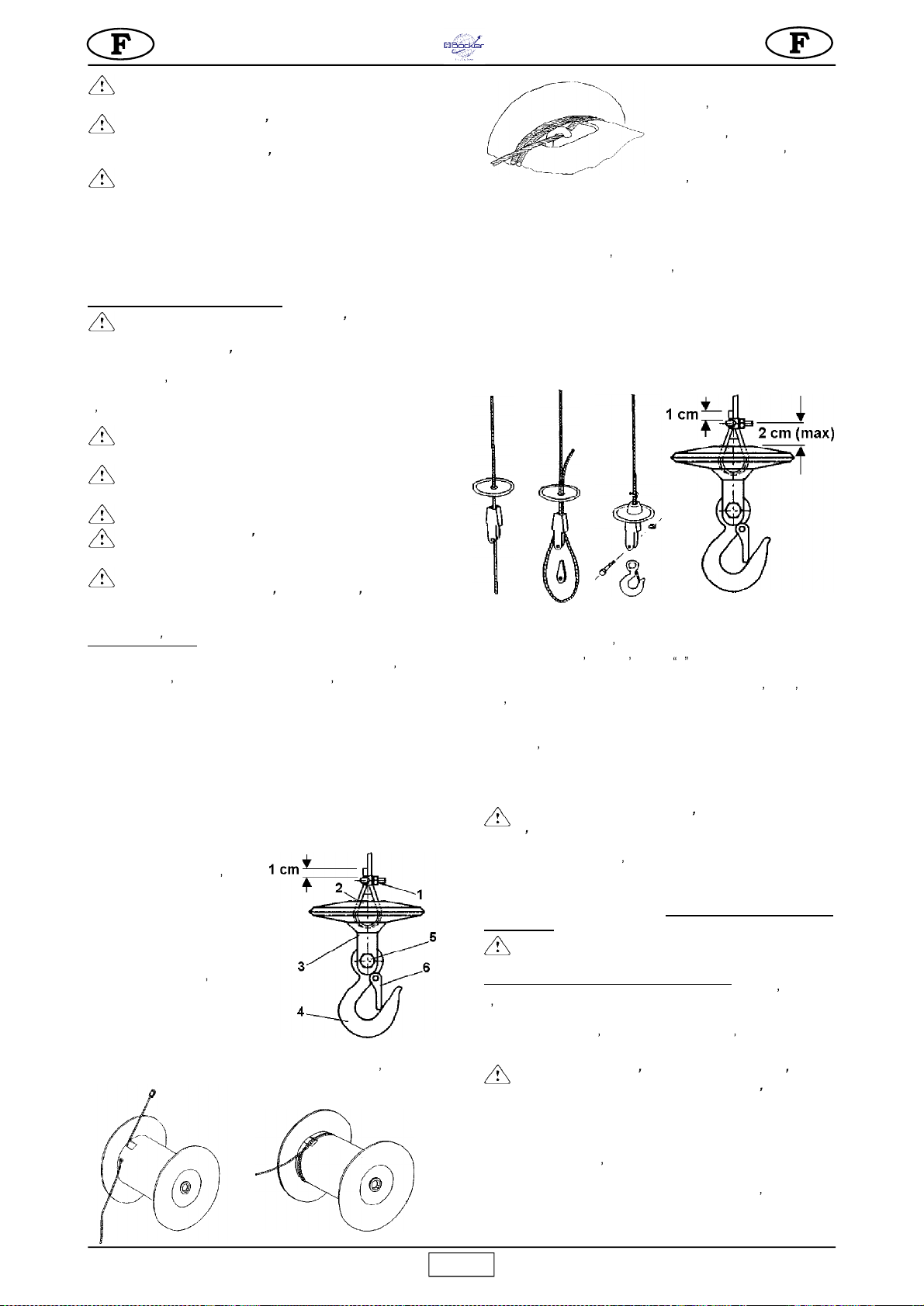
7.1.1 REMPLACEMENT DU
CÂBLE (fig. 4)
Le remplacement doit être effectué
par un responsable de l entretien
compétent.
Démontez le crochet 4 en dévissant
le boulon 5 (fig. 4.1).
Démontez la borne 1, poussez la
cale 2 et dégagez le câble de la poulie
à coin 3.
Le tambour est doté d un dispositif
de sorte à laisser deux spires même
lorsque le câble est entièrement
déroulé pour éviter de forcer le point
de raccordement du câble.
Si vous devez remplacer le câble, montez-le en ayant soin de respecter
cette condition. Déroulez tout le câble. Dégagez-le de l intérieur du
tambour en le faisant passer à travers le
trou et la fente.
Introduisez le nouveau câble
dans l orifice prévu à cet effet
et faites-le sortir de la fente du
noyau, à l intérieur du tambour
puis serrez la borne à l extrémité
en laissant environ 1 cm de câble
libre (fig. 4.2). Tirez sur le câble jusqu à ce que la borne entre en
contact avec la paroi interne du tambour.
Enroulez deux spires complètes en ayant soin de laisser le câble en
contact avec le tambour (fig. 4.3).
Lorsque vous arrivez sur la deuxième spire, faites passer le câble
sous le crochet placé à l intérieur de la fente du tambour (fig. 4.4).
Tirez sur le câble et assurez-vous qu il entre en contact avec toute la
circonférence du cylindre.
Enroulez le câble en le disposant correctement, spire contre spire, en
couches superposées.
Enfilez le câble en acier dans le contrepoids et dans la poulie à coin
(fig. 4.5).
Faites repasser le câble dans la poulie à coin et dans le contrepoids.
Insérez le coin entre la poulie et le câble en acier.
Tirez sur le câble jusqu à serrer tous les composants entre eux.
Bloquez le câble à laide de l étau en U en laissant la partie plate en
contact avec le câble de traction.
Montez le crochet sur la poulie à coin en le bloquant à l aide d une vis
et dun écrou de sûreté.
Vérifiez que le fin de course de montée fonctionne lorsque le
contrepoids atteint le levier.
Effectuez l essai de charge indiqué au paragraphe 5 et enregistrez le
remplacement effectué dans le tableau 2.
7.1.2 CONTRÔLES PÉRIODIQUES
-
Vérifiez chaque jour de visu l état du câble ou chaque
fois qu il présente des contraintes anormales (torsions, forts
encastrements dans les spires, pliages ou frottements).
Remplacez le câble dès qu il présente les problèmes indiqués fig. 13.
Chaque trimestre, examinez soigneusement le câble et en particulier
les extrémités en enregistrant le résultat sur la
fiche
présente dans le
manuel (tableau 2) qui devra être conservée par le responsable
du chantier.
- Remplacez le câble une fois par an.
7.2 RÉGLAGE DU FREIN DU MOTEUR (fig. 5)
Le frein du moteur électrique intervient en l absence
dalimentation électrique au moteur.
En cas de réduction de la capacité de freinage faire contrôler
par le préposé à l entretien compétent l élévateur qui si
nécessaire pourvoira au réglage.
-
Attention! Avant d intervenir sur le frein s assurer
que la charge est décrochée et que la fiche d alimentation
électrique soit débranchée et le moteur froid.
7.2.1. Réglage du freinage
Retirer le bouchon 5 du cache ventilateur 1.
Augmentation du freinage: tourner en sens horaire
progressivement l écrou autobloquant 6 et vérifier le
décrochage du frein en descente.
Diminution du freinage: tourner en sens horaire l écrou 6.
Fig. 4.1
Fig. 4.5
Fig. 4.4
Fig. 4.3
Fig. 4.2
10
Boy
7.2.2. Réglage entrefer.
En cas de blocage du frein et d une usure, régler l entrefer de
la façon suivante.
Retirer le couvre ventilateur 1 et démonter le ventilateur 2.
Desserrer les 3 vis à 6 pans creux 3.
Blocage frein:
tourner en sens horaire la bague 4 pour
augmenter l entrefer 7 et débloquer le frein en contrôlant la
distance (0,6-0,8 mm).
Consommation frein:
tourner en sens antihoraire la bague
4 pour réduire l entrefer, en contrôlant la distance (0,6-0,8 mm).
Serrer fortement les 3 vis à 6 pans creux 3, remonter le
ventilateur et le couvre-ventilateur.
Pour contrôler la tenue du frein, après le réglage, tester plusieurs
fois le freinage en pleine charge.
7.3 GRAISSAGE DU MOTORÉDUCTEUR
Le groupe motoréducteur ne doit pas perdre d huile : la présence
de fuites importantes peut être un signe de lésion dans la
structure en aluminium. Dans ce cas, réparez immédiatement le
carter ou remplacez-le.
- Vérifiez le niveau de lhuile à travers le témoin chaque
fois que vous mettez la machine en marche. Faites l appoint
si cela s avère nécessaire, en utilisant le bouchon placé sur le
réducteur. Vidangez au bout de 2000 heures de service en
utilisant de l huile à engrenages, viscosité ISO VG 460 à 40°C
(SAE 90-140).
- Lhuile usée est un déchet spécial qui doit être éliminé
conformément à la législation en vigueur.
7.4 INSTALLATION ÉLECTRIQUE
Contrôlez l intégrité de la protection isolante de la boîte à boutons et
remplacez-la au cas où le joint serait endommagé. Utilisez des pièces
dorigine
STEINWEG.
Vérifiez si le câble en acier qui relie la boîte à
boutons au tableau électrique est plus court que le câble électrique
afin de ne pas forcer dessus.
8. DÉMONTAGE DE LÉLÉVATEUR
Retirez la charge éventuellement fixée au crochet.
Enroulez le câble complet sur le tambour. Débranchez lengin de la
prise électrique.
Retirez la goupille sur le pivot de soutien et dégagez le châssis porteur
rotatif.
Démontez le chariot de l élévateur en utilisant le chevalet après l avoir
dégagé de ses guides et avant de retirer les lests.
9. TRANSPORT ET MISE HORS SERVICE
- Ne laissez pas l élévateur installé sans contrôle sans avoir coupé
lalimentation et enroulé entièrement le câble sur le tambour.
Lorsque la machine reste arrêtée pendant un certain temps, il est
conseillé de la protéger contre les agents atmosphériques.
- Pendant le transport, protégez les différentes pièces de la machine
contre les chocs et l écrasement pour ne pas compromettre son
fonctionnement et sa résistance mécanique.
10. MISE AU REBUT DE LÉLÉVATEUR
Respectez la procédure suivante :
a) videz l huile par le bouchon;
b) séparez les différents composants en plastique et électriques
(câbles, boîtes à boutons, etc.);
c) divisez les composants métalliques par type de métal (acier,
aluminium, etc.);
Fig. 5
INCONVÉNIENTS
CAUSES
REMÈDES
La machine ne
fonctionne pas en
appuyant sur les
boutons de mise en
marche (montée et
descente).
Le bouton d arrêt
durgence est enfoncé.
Désactiver le bouton en le
faisant tourner.
La tension n arrive pas
à la machine.
Contrôler la ligne.
La prise et la fiche
électrique ne sont pas
reliées correctement.
Reconnecter
correctement.
Linterrupteur de
protection du boîtier
externe d alimentation
est inervenu
Réarmer le
magnétothermique.
La machine function-
ne en descente mais
pas à la montée
Fin de course de
montée en panne.
Réparer
La rallonge
télescopique a du
mal à se déplacer
horizontalment.
La poignée de blocage
est serrée.
Desserrer.
Si linconvénient persiste. S adresser à un centre
dassistance STEINWEG..
Lorsque les composants sont classés, éliminez-les dans des centres
de récupération agréés.
- N éliminez rien dans la nature afin d éviter les
accidents et la pollution.
11. INCONVÉNIENTS - CAUSES - REMÈDES
12. EN CAS DE PANNE DE LA MACHINE AVEC CHARGE
SUSPENDUE
- Retirez, si possible, la charge en y accédant par le niveau auquel elle
se trouve, puis enlevez l élévateur et procédez aux opérations
dentretien.
- En utilisant un autre appareil de levage (de capacité suffisante) placé
plus haut, suspendez l appareil endommagé en l élinguant dans la
zone de la charge et à proximité des fixations.
Soulevez-le lentement de sorte à le dégager puis faites descendre le
tout au sol.
- N essayez pas d intervenir sur lécrou de réglage du frein parce qu il
séchapperait.
- N essayez pas de réparer la panne en intervenant sur la machine
avec la charge suspendue.
13. NIVEAU DE BRUIT À PROXIMITÉ DE LOUÏE DE
L OPÉRATEUR
Le niveau Lp(A) indiqué dans le tableau DONNÉES TECHNIQUES
correspond au niveau équivalent pondéré de pression sonore
en échelle A prévu par la norme 2000/14/CE. Ce niveau est
mesuré à vide, à la hauteur de la tête de l opérateur en position
de travail, à 1,5 mètre de l appareil, en considérant les différentes
conditions de travail.
11
Boy
Fig.2
Dear customer,
Congratulations on purchasing an Steinweg-Böcker-
Baumaschinen GmbH hoist, a reliable and innovative product
created through years of experience.
-
WORKING IN SAFETY: The following instructions
are essential for safety.
This OPERATING AND MAINTENANCE manual must be kept on
site by the foreman and must be accessible for consultation at
all times.
The manual is be considered an integral part of the machine
and must be kept for future reference (EN ISO 12100-2) until
the machine is scrapped. If it is damaged or lost, a replacement
copy can be requested from the hoist manufacturer.
The manual contains important information on site preparation,
installation, operation, maintenance and ordering of spare parts.
The installer and operator must have adequate experience and
knowledge of the machine.
To guarantee complete safety of the operator, safe operation
and a long service life, follow the instructions in this manual
and observe current applicable legislation regarding safety and
accident prevention in the workplace (use of suitable footwear,
clothing, hard hats and safety harnesses, proper installation of
railings around drops, etc.).
-
It is strictly forbidden to modify the steel structure
or working parts of the machine in any way.
Steinweg-Böcker-Baumaschinen GmbH will accept no
responsibility for failure to comply with legislation and standards
governing the use of hoisting equipment, in particular: improper
use, incorrect power supply, inadequate maintenance,
unauthorised modifications, tampering and/or damage and partial
or complete failure to observe the instructions contained in this
manual.
-
Steinweg-Böcker-Baumaschinen GmbH reserves
the right to modify the characteristics of the hoist and/
or the contents of this manual without any obligation to
update previous machines or manuals.
1. GENERAL DESCRIPTION
-
Warning: Use of lifting equipment requires great
skill and care. The hoist must be used by skilled and
properly instructed personnel only.
-
1) The machine is designed exclusively for lifting
materials and for use on building sites.
-
2) The machine must not be used for lifting people
and/or animals.
-
3) The machine must not be used in potentially
explosive atmospheres or underground.
The machine consists essentially of (fig. 1):
- Drum type winch fitted to reduction gear shaft (3), wire rope
(1), lift hook (2) and counterweight (10).
- Gearmotor consisting of a self-braking electric motor (4) and
an oil-bath reduction gear unit (14).
- Electrical system (5).
- UP position control lever (9).
- DOWN position control lever (17).
- Rotary frame (7) with telescopic arm (6), loocking handle (8) and
frame locking lever (11).
- Thermal overload (16) which stops the winch when the current
exceeds the nominal value (press to reset).
- The winch has three types of pendant control (15)
1.5 m lead direct pendant
30 m low voltage (24V) pendant.
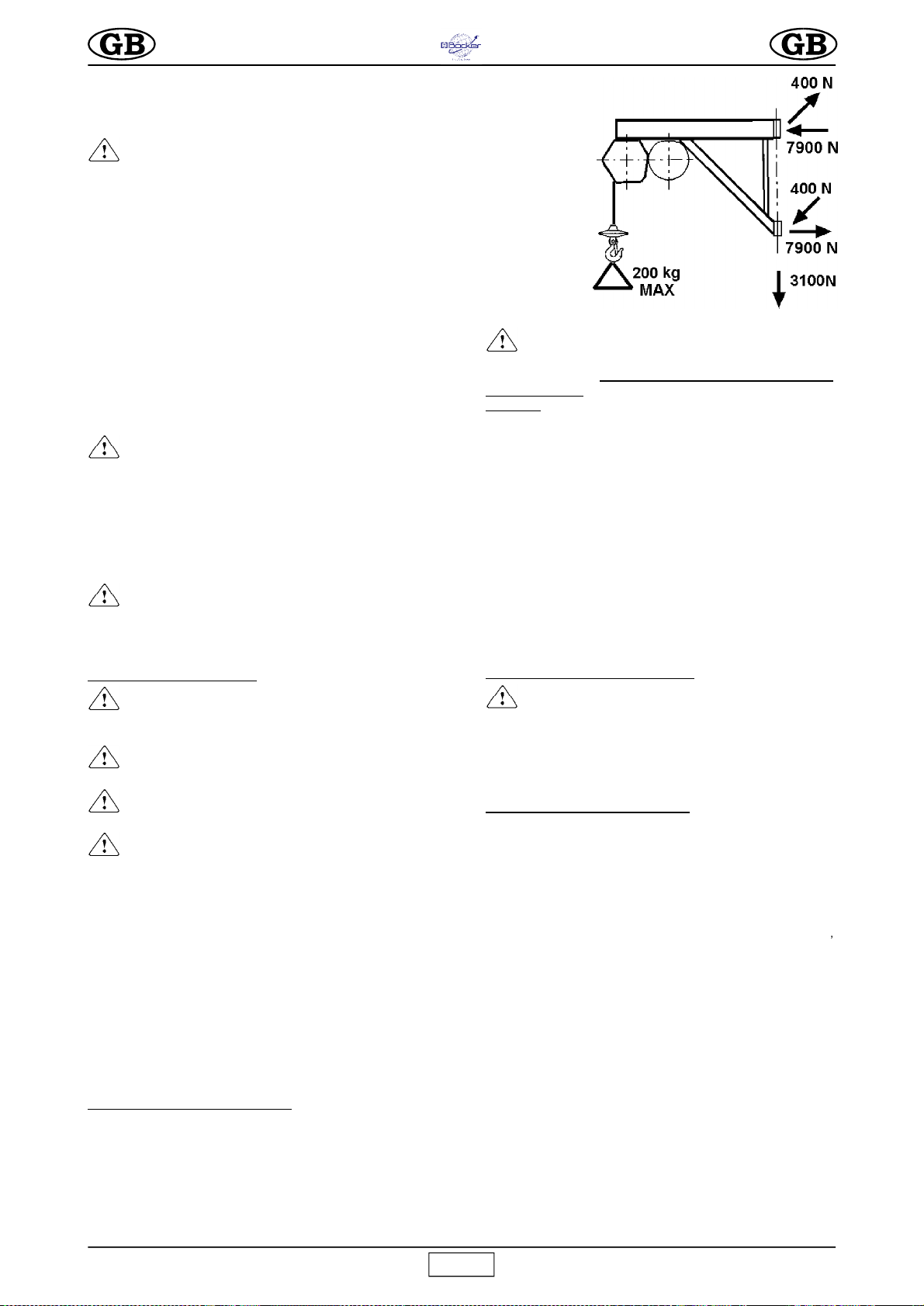
2. HOIST SUPPORT STRUCTURE
The structure on which the hoist is mounted must be able to
withstand the stresses generated during operation (fig. 2).
The 400 N force is perpendicular to the 5000 N force. Since the
hoist is able to rotate on the supporting hinges, these forces
must be verified in all possible positions of the hoist.
Steinweg-Böcker-Baumaschinen GmbH offers a wide range of
supports (see figures 7, 8, 9, 10, 11) for use on building sites, designed
to suitably transfer the stresses to the building structures.
-
IMPORTANT
The EC declaration of conformity enclosed with this
manual is valid only if components manufactured
exclusively by Steinweg-Böcker-Baumaschinen GmbH
are used
(hoist and support structures).
If this condition is not satisfied, this declaration is valid
only for the hoist.
The installer should compile a new EC declaration of
conformity, after verifying all requirements stated in
the Machinery Directive 2006/42/EC for the equipment
and support assembly.
The forces on the support couplings must be accounted for in
calculations for the supporting structures (scaffolding,
balconies, ceilings, etc.) made by a qualified technician.
If the hoist is to be mounted on scaffolding, the latter must be
adequately braced against wind (see fig. 12).
Follow the instructions provided for installation of the various
supports.
If supports with different capacities from the hoist are used,
the permissible capacity of the weakest element in the system
must be marked on the assembly in a clearly visible position.
2.1 PREPARING THE WORKPLACE
- The loading access area must be protected by a
rail at least 1 m high and with a foot stop.
- Make sure that the lifting run is free from obstacles and make
sure that no one can lean out from intermediate floors.
- Cordon off the ground loading area to ensure that no one
enters the area during lifting.
3. MOUNTING THE HOIST (fig. 1)
1) Only competent, trained personnel may assemble and ope-
rate the hoist.
Given the weight of the hoist, it must be transported and
installed by an adequate number of operators to avoid
hazardous situations.
2) The maximum working height (30 m) corresponds to the
gearmotor position, i.e. it is measured from the top hinge of the
support.
3)
Secure the support to the building and check the support pins
vertical alignment (12); then lift the locking lever (11) to insert the
frame bushings (7) onto the pins and fit the split pin retainer (13).
4) Fit the telescopic arm (6) to the frame (7) at its minimum extension,
screw on the locking handle and washer in the threaded hole through
its slot and tighten fully.
5) Ensure that the hoist is completely level by means of a spirit
level placed on the top plate of the drum. (fig. 1).
6)
The telescopic arm (6) allows a lifting excursion from the
axis of the pins of between 720 and 1120 mm.
7) When assembling on a trestle support, fit the telescopic arm (6) to
the carriage through the securing holes (fig. 12) using bolts and
locknuts. For the rest, follow the instructions for the trestle support.
5)
Insert the direct pendant control (1.5 or 5 m lead) plug in the
electrical panel (5)
and hook the spring clip of the steel cable
onto the ring on the electric panel to avoid pull on the electric
cable.
For the 24V low voltage pendant fix the electrical panel on the frame
(7) and insert the connector in the panel (5).
All pendant controls have 3 pushbuttons (Fig. 3):
ORIGINAL TEXT

12
Boy
black: down
white: up
red: emergency stop.
6) Release the hook.
4. CONNECTION TO THE
ELECTRICITY MAINS
- Make sure that the mains voltage corresponds to the rating on
the machine s rating plate.
- Also ensure that the mains voltage is within the range 210 V
to 235 V with the hoist operating at full load.
-
The electrical supply line must be fitted with both overcurrent and
differential type protection devices and the earth wire must have
the same cross-section as the live wire. The wires must be sized
taking into account the operating currents and the length of the line
to avoid excessive voltage drops (see Table 1).
Do not use extension leads wound onto drums.
- The power supply cable must be suitable for frequent handling
and must have an abrasion-resistant sleeve (e.g. H07RN-F).
- Connect the machine s plug to a 16 Amp EEC socket with an
IP67 protection factor and tighten up the securing collar.
- The hoist is now ready for testing.
5. TESTING
- Warning!! Testing must be carried out by qualified
personnel only. Take all necessary safety precautions.
- Warning: the hoist must be tested before use.
Before testing the hoist make sure that it has been correctly
installed.
1) Lower the unloaded rope to the lower loading position by
pressing the down button, and check that at the end of its travel
three turns of rope remain on the drum.
2)
No-load test. Apply a small load (20 kg) and check that the
machine works correctly by running a complete up/down cycle.
Test the up, down and emergency stop buttons and check that
the up limit switch and the electric motor brake work correctly
and that the cable winds correctly onto the drum.
3)
Load test. Load the hoist with the maximum allowable load.
Run a complete up/down cycle to test the stability of the supports
and the motor brake.
After the test, check the support structure for failure and
slippage and recheck the horizontal alignment of the drum (using
a level as shown in fig. 1).
4) The hoist is fitted with a safety which stops travel at the UP (9) and
fully unwound positions (17) to avoid the rope winding on in the wrong
direction.
Do not depend on this safety to stop the winch; release the control
button to stop the winch instead.
-
IMPORTANT! Limit switch activation can occur either
due to incorrect working height or due to other problems
which may prejudice correct hoist functioning. After the limit
switch has been activated, the hoist installation and
components must be checked (rope, drum, shaft etc.)
When testing is completed, fill in the test report with the date,
installation check and signature (Table 2) along with any other
comments.
- The test procedure described above, complete
with no-load (2) and load (3) tests, must be performed
every time the machine is installed.
6. SAFETY WARNINGS AND OPERATING PRECAUTIONS
-
1) Never lift loads exceeding the capacity of the
elevator.
-
2) Never allow persons to remain below suspended
loads.
-
3) Never try to lift loads anchored to the ground
(e.g. embedded posts, plinths, etch.).
-
4) Ensure that the load is securely connected to the
elevator hook and also close the safety catch (ref.6 fig.
4.1).
-
5) If the load requires accessories to be attached to
be hooked up, these must be certified and approved
(harnesses, ropes, slings, etc.). The weight of these
accessories must be subtracted from the maximum
capacity.
-
6) Ensure that no part of the load protrudes during
the lifting phases.
-
7) Before releasing the load, ensure that it is in a
stable position.
-
8) A suspended load must never be detached to
cause sudden release or by cutting the slings, causing a
backlash movement of the entire structure.
-
9) Never move hands or parts of the body near the
drum during operation, as this constitutes a risk of
entrapment in the ropes unwinding, with the risk of
serious accidents.
-
10) Never move hands or parts of the body near the
counterweight during the ascent phase, as this constitutes a
risk of crushing on contact with the limit switch lever.
-
11) Avoid use in adverse weather conditions
(strong winds or storms) as the load is not guided.
-
12) The control position and lighting conditions
must ensure perfect visibility of the load throughout
travel.
-
13) Ensure that all guards and safety devices are
fitted.
-
14) During use, check that the rope unwinds
correctly, turn on turn, without slackening or twisting,
which can cause damage to the rope. If this occurs,
unwind the rope and rewind correctly keeping the rope
tensioned at all times.
-
15) Ensure that the travel and work area is free of
obstacles throughout the height and take necessary
precautions to prevent persons from leaning out of
intermediate floors.
-
16) Delimit the lower load area to prevent persons
from being present during lifting.
-
17) Keep children at a safe distance from the
elevator.
-
18) When the elevator is not in use, do not allow
unauthorised personnel access or operation.
-
19) Use of the elevator for oblique tractions is
strictly prohibited (over 5° with respect to vertical angle).
-
20) Never rotate the elevator on the pins by pulling
the pendant control; it must always be rotated manually
from the frame.
-
21) Do not leave a suspended load unattended.
Raise or lower it and unload it.
-
22) During lifting or lowering, never allow the
load to turn as this may cause the rope to break.
-
23) Before leaving the elevator unattended, remove
the load, wind the rope completely onto the drum, and
detach the power plug from the mains.
-
24) When a load is to be raised or lowered, this
must be done in such a way as to minimise dangerous
sideways and vertical movements.
When operation is resumed after an extended period of disuse
(e.g. overnight) the entire machine must be tested under no-load
conditions before starting (as described in section 5, point 2).
7. CHECKS AND MAINTENANCE
-
Warning! All maintenance work must be carried
out with the machine switched off, unloaded and
disconnected from the mains.
- Repairs must be made by qualified personnel or by the
STEINWEG
technical service.
Fig. 3

13
Boy
- Use only
STEINWEG
original spares.
-
Check the motor brake every 6-7 days.
-
Make sure that the notices and inscriptions on the
machine remain legible.
-
Keep the machine clean of dirt.
-
Check operation of the UP limit switches at the
start of every work shift.
-
Check the electrical cable for accidental damage
at the start of every work shift.
7.1 WIRE ROPE
Use exclusively new ropes with characteristics as specified
below complete with certificate of conformity and identification.
- External diameter
5 mm
- Type 133 wires anti-spin
- Strand strength
1.960 N/mm
2
- Minimum breaking load
16 kN
- Length
31 m
- Surface treatment galvanised, greased
- The
STEINWEG
reference code is given in the spare parts
table.
7.1.1 REPLACING THE ROPE (Fig. 4)
The rope must be replaced by a
qualified service technician.
Remove the hook (4) by
unscrewing bolt (5) fig. 4.1.
Remove the clamp (1), push on
the wedge (2) and extract the
rope from the block (3).
The drum is fitted with a device
which ensures that 2 turns of
rope are always wound on even
when the rope is unwound to its
limit. This stops the rope
attachment from being
overforced.
The rope must be attached in this way.
Completely unwind the rope. Extract
from the inside of the drum through the
hole and slot.
Remove it from inside the drum through
the hole and slot. Insert the new rope
in the hole and thread it through the
slot in the drum tube. Tighten the clamp
at the end, leaving about 1 cm of rope
free (fig. 4.2), and pull the rope until
the clamp comes into contact with the
inner wall of the drum.
Wind on two complete turns
keeping the rope in contact with
the drum (Fig. 4.3).
On the second turn pass the rope
under the hook inside the drum slot
(Fig. 4.4).
Tension the rope for good contact
with the drum surface.
Now wind on the rope in adjacent
turns, one layer at a time.
Insert the wire rope into the
counterweight and the block (Fig.
4.5).
Pass the rope back through the
counterweight and the block.
Insert the wedge between the block
and the rope.
Pull the rope to tighten all
components. Now lock the rope with a U-clamp so that the flat
part remains in contact with the lifting section of the rope.
Fit the hook to the block and tighten the bolt and locknut.
Check that the UP limit switch operates when the counterweight
touches the lever.
Run the load test described in paragraph 5 and note down in
Table 2 the fact that the rope has been changed.
7.1.2 PERIODIC CHECKS
- Visually inspect the condition of the rope daily
and whenever it is subjected to abnormal strain
(twisting, bending, kinks or abrasion).
Replace the rope when defective (Fig. 13).
Every three months inspect the entire rope carefully and in
particular the ends. Note down the results in the chart (Table 2)
which must be kept by the site foreman.
- Replace the rope at least once a year..
7.2 ADJUSTING THE MOTOR BRAKE (Fig. 5)
The electric motor brake is engaged in the event of power
supply failure to the motor.
I
n the event of reduced braking power, the hoist must be checked by
a skilled maintenance engineer, for adjustments if necessary.
-
CAUTION! Before working on the brake, ensure
that the load is removed, the electric power plug is
disconnected and the motor is cool.
7.2.1. Braking adjustment
Remove cap 5 from fan cover 1.
Increased braking: turn locknut 6 gradually counter-clockwise
and check that the brake disengages in descent.
Decreased braking: turn locknut 6 clockwise.
7.2.2. Air gap adjustment
If the brake blocks or in the event of excessive wear, the air
gap should be adjusted as follows.
Remove fan cover 1 and disassemble fan 2.
Loosen the three hex screws 3.
Brake block: turn ringnut 4 clockwise to increase air gap 7 ad
release the brake, checking the gap distance (0.6-0.8 mm).
Brake wear: turn ringnut 4 counter-clockwise to reduce the air
gap, checking the gap distance (0.6-0.8 mm).
Tighten the three hex screws 3 fully down and refit the fan
and fan cover.
To check brake grip, after adjustment, test braking several times
under full load.
7.3 GEARMOTOR LUBRICATION
The gearmotor unit must not develop oil leaks. Leaks may indi-
cate damage to the aluminium casing. In this case, reseal or
replace the casing.
Fig. 4.1
Fig. 5
Fig. 4.5
Fig. 4.4
Fig. 4.3
Fig. 4.2
14
Boy
-
Check the gearmotor oil level through the sight
glass before every start-up. Refill as required. The oil
should be changed approximately every 2000 hours. Use
gear oil with ISO VG 460 viscosity at 40°C
(SAE 90-140)
.
-
Spent oil is classed as special waste and must be
disposed of in accordance with current applicable
legislation.
7.4 ELECTRICAL SYSTEM
Check the condition of the insulating pendant control case. If it
is damaged replace it with an original
STEINWEG
spare. Make
sure that the steel cable connecting the pendant control to the
electrical panel is shorter than the electrical cable to protect
against pulling.
8. DISMANTLING THE HOIST
Remove all loads from the hook.
Wind the wire rope completely onto the drum. Disconnect the
power plug.
Remove the split pin from the support hinge and remove the
rotating frame.
If a trestle is being used, the carriage must be removed from the
hoist after it has been taken off the guides and before the
counterweight is removed.
9. TRANSPORT AND STORAGE
- Do not leave the installed hoist unattended without first
disconnecting the electric power supply and winding the rope
completely onto the drum.
When the machine is to be stored for a long period of time, make
sure that it is protected against atmospheric agents.
- During transport protect the machine from shock and crushing
which can adversely affect its functionality and mechanical
strength.
10. SCRAPPING THE HOIST
To scrap the machine at the end of its service life, carry out the
following steps:
a) Drain out the oil by removing the oil plug.
b) Separate the various plastic and electrical components
(cables, pendant control, etc.).
c) Divide up the metal components according to the type of
metal (steel, aluminium, etc.).
After the various components have been separated, dispose
of them through authorised disposal centres.
-
Dispose of properly. These components can cause
accidents and pollution.
FAULT CAUSE SOLUTION
The machine
does not lift or
lower on
command
Emergency stop
button engaged
Turn to
disengage
No power to
machine
Check mains
cable
Plug not inserted Insert the plug
Power board
cutout tripped
Reset the
overload trip
Difficult to
lengthen the
telescopic arm
Lock knob too
tight.
Slacken.
The machine
lowers but does
not lift.
Up limit switch is
faulty.
Repair.
IF THE FAULT PERSISTS Contact
STEINWEG
Technical Service
11. TROUBLESHOOTING
12. PROCEDURE IN EVENT OF FAULT WITH LOAD
SUSPENDED
- If possible remove the load from the nearest level, then
dismantle and service the hoist.
- If this is not possible, use another lifting machine (with adequate
lifting capacity) from higher up and suspend the faulty hoist
both at the load and at the hoist attachment point.
Lift the faulty hoist slowly off its fitting, then lower the entire
assembly to the ground.
- Do not attempt to turn the brake adjustment nut, as it would
become uncontrollable.
- Do not attempt to repair the fault on the machine with the load
suspended.
13. NOISE LEVEL AT THE OPERATOR S EAR
The level Lp(A) given in the TECHNICAL DATA chart
corresponds to the weighted equivalent sound pressure level
on scale A of European Directive 2000/14/EC. This level is
measured with no load, at the operator s head in the working
position 1.5 metres away from the instrument, considering the
different working conditions.

Boy
15
APPAREIL DE LAVAGE
HO IST
AUFZUG
PO UTRE
BEAM
TRÄ GER
PO UTRE
BEAM
TRÄ GER
Cod. 1199103
POTEAU POUR INTERIEUR
HOIST FRAME FOR INTERMEDIARY FLOORS
INNENSTÜTZE
PA RAPET
PA RAPET
BRÜSTUNG
NI VEAU
SPIRIT LEVEL
W A SS ER W AA GE
ZONE DE TRAVAIL OPÉRATEUR
OPERATOR WORK ZONE
ARBEITSBEREICH DES BEDIENERS
POSITION D'APPUI SUPÈRIEURE
POSITIONING TOP FOOTANORDNUNG
DER OBEREN AUFLAGE
Abb. 7 - Fig. 7
APPAREIL DE LAVAGE
HO IST
AUFZUG
Abb. 8 - Fig. 8
cod. 1199136
KIT POUR POTEAU D' EXTERIEUR
HOIST FRAME FOR ROOFS
BAUSATZ AUßENSTÜTZE
NI VEAU
SPIRIT LEVEL
W A SS ER W AA GE
PA RAPET
PA RAPET
BRÜSTUNG
CONTENEUR LEST
COUNTER W EIGHT
BALLAST
CONTENEUR LEST
COUNTER W EIGHT
BALLAST
PA RAPET
PA RAPET
BRÜSTUNG
ZONE DE TRAVAIL OPÉRATEUR
OPERATOR WORK ZONE
ARBEITSBEREICH DES BEDIENERS
APPAREIL DE LAVAGE
HO IST
AUFZUG
Abb. 9 - Fig. 9
FIXATION SUR ECHAFAUDAGE
HOIST FRAME FOR SCAFFOLDING
GERÜSTBEFESTIGUNG
cod. 1199171
POSITION DE TRAVAIL
WORK POSITION
ARBEITSPOSITION
ZONE DE TRAVAIL OPÉRATEUR
OPERATOR WORK ZONE
ARBEITSBEREICH DES BEDIENERS
Abb. 10 - Fig. 10
cod. 1199151
- RALLONGE POUR POTEAU
- JIB EXTENSION FOR INTERMEDIARY FLOOR AND ROOF FRAMES
- SCHWENKARM FÜR-GESCHOßSTÜTZE
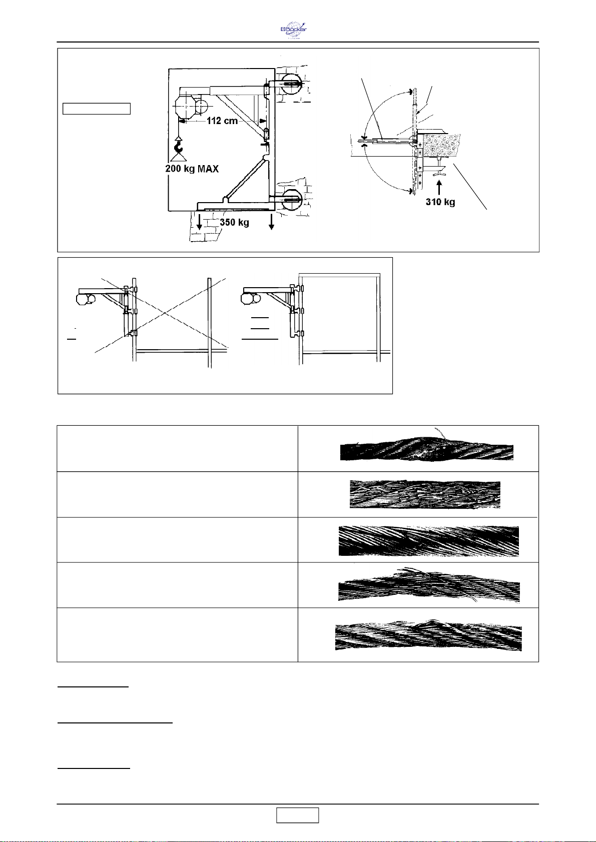
Boy
16
Fig.13
ERSATZTEILE:
Für Ersatzteilbestellungen bitte die folgenden Angaben machen: 1) Maschinentyp 2) Jeweils
zugeordnete Art.-Nr. und Positionsnummer 3) Seriennummer und Baujahr (Angabe auf dem Maschinenschild)
PIECES DE RECHANGE:
Pour toutes les commandes de pièces de rechange, veuillez indiquer: 1 - Le Type de
machine 2 - Le Numéro de code et de référence se trouvant en face de chaque définition 3 - Le Numéro de série
et l'année de construction se trouvant sur la plaquette d'identification de la machine
SPARE PARTS:
All orders for spare parts must indicate the following: 1 - Type of machine.2 - Part number and
position number of each part.3 - Serial number and year of manufacture reported on the machine's identification
plate.
APPAREIL DE LAVAGE
HO IST
AUFZUG
Abb. 11 - Fig. 11
FE NÈT RE
WINDOW
FE NST ER
cod. 1199106
POTEAU POUR FENETRE
HOIST FRAME FOR WINDOWS
FENSTERKLEMMARM
POSITION DE TRAVAIL
WORK POSITION
ARBEITSPOSITION
ZONE DE TRAVAIL OPÉRATEUR
OPERATOR WORK ZONE
ARBEITSBEREICH DES BEDIENERS
NO!
NON!
FALSCH!
- Die Belastungswerte auf den
Trägern gehen vov einem
statischen Überlastung von 1,25
aus.
- Les forces sur les appuis ont été
calculées avec un coefficient de
surcharge de 1,25.
- The forces on the links are
evaluated considering a overload
coefficient of 1,25.
Abb. 12 - Fig. 12
OUI!
YES!
RICHTIG!
SCHLAUFENDIBILDUNG
POINTS D' APLATISSAGE VISIBLE
VISIBLE FLATTENED POINTS
ABFLACHUNGEN ODER AUFWÖLBUNGEN
CORROSION INTERIEURE OU EXTERIEURE
INTERNAL OR EXTERNAL CORROSION
BRECHEN EINZELNER DRÄHTE
RUPTURE D' UN BRIN
BREAKING OF ONE STRAND
FEHLEN EINER LITZE
RUPTURE DE FILS
BREAKING OF SINGLE WIRES
VERSCHLEIß=MATERIALVERLUST UNREGELMÄSSIGE OBERFLÄCHE
FORMATION DE BOUCLES
LOOPS
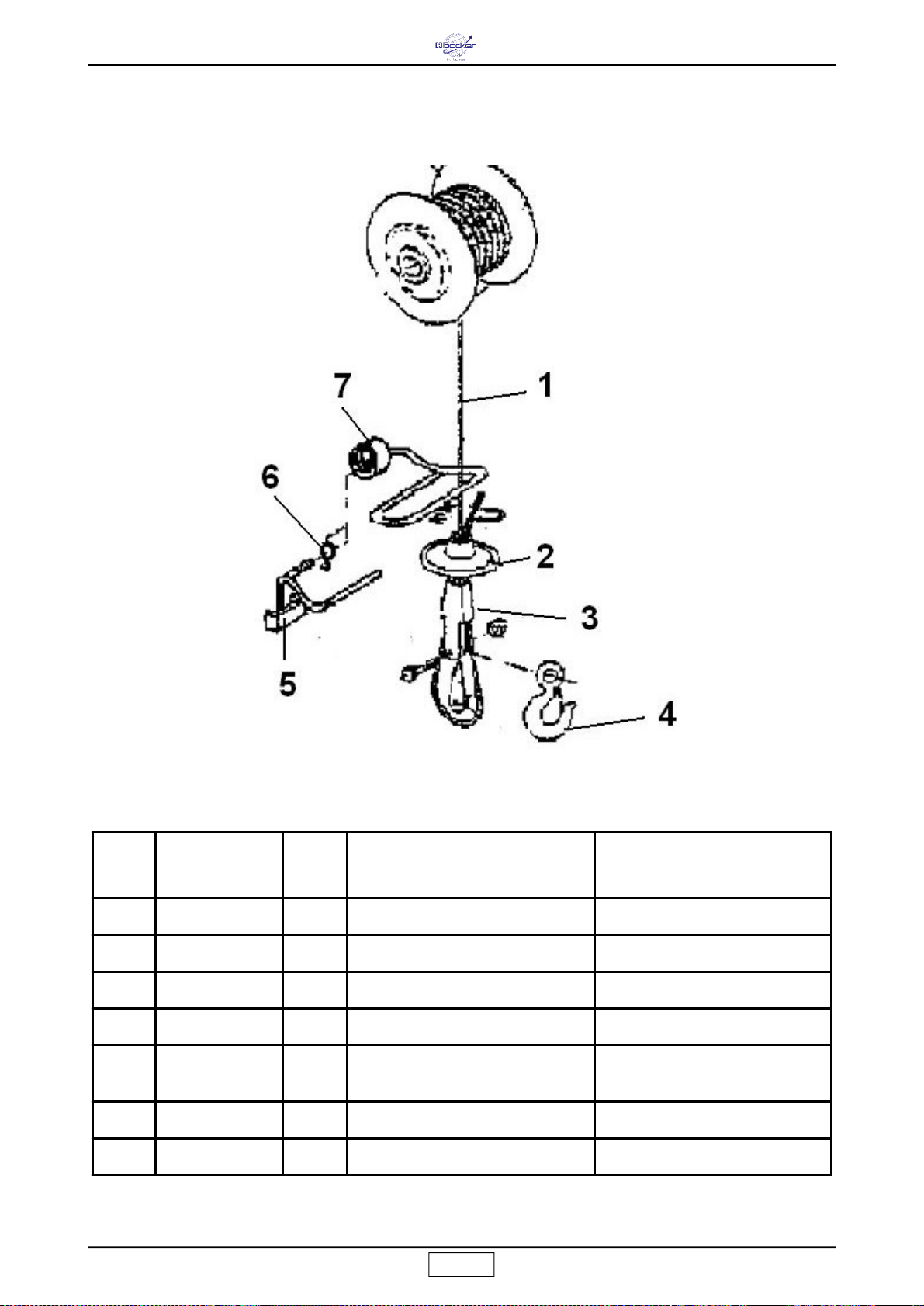
Boy
17
Pos.
Ident- Nr.
Stck
Benennung
Name
1
0000290032
1 DRAHTSEIL - 31m WIRE ROPE
2
0000621035
1 GEGENGEWICHT CABLE WEIGHT
3
0220132000
1 SEILSCHLOSS KOMPL. WEDGE BLOCK
4
0216603000
1 LASTHAKEN KOMPL.
HOOK
5
0000621044
1
HEBEL
DOWN POSITION
CONTROL LEVER
6
0000621055
1
FEDER
SPRING
7
0000621034
1
HEBEL
LIMIT LEVER
Drahtseil01.01
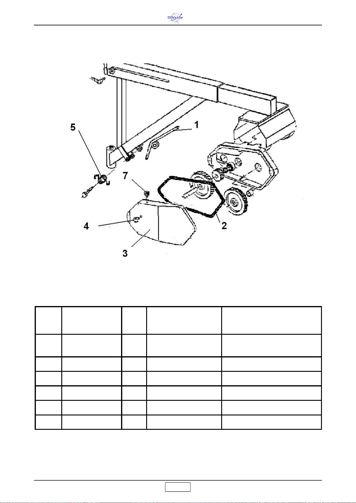
Boy
18
Pos
Ident- Nr.
Stck
Benennung
Name
1
0000621054
1
HEBEL
FRAME LOCK LEVER
2
0000621048
1
DICHTUNG
GASKET
3
0000621037
1
FLANSCH
REDUCTION GEAR FLANGE
4
0000621036
1
SCHAUGLAS
OIL LEVEL PLUG
5
0000621051
1
HEBELFEDER
SPRING
7
0000621049
1
ÖLSTOPFEN
OIL PLUG
Rahmen02.01
Table of contents
Languages:
Other Böcker Lifting System manuals


Popular Lifting System manuals by other brands

Nussbaum
Nussbaum ATT HYMAX S 3000 Operating manual, Inspection book

Hewi
Hewi 805 Classic Series installation instructions

Challenger Lifts
Challenger Lifts CL10 Installation, operation & maintenance manual

Upright
Upright LX31 Operator's manual

Sealey
Sealey MC365A.V2 instructions

VMB
VMB TL-054 instructions


Kogan
Kogan CERTA CTPLFT11FTA user guide

BorMann
BorMann PRO BTC6200 manual

Paragon Pro
Paragon Pro CABINETIZER 72 Operator's manual

Challenger Lifts
Challenger Lifts E12 Installation, operation & maintenance manual

morse
morse Hydra-Lift Drum Karrier Operator's manual

GMV
GMV GLT 81-21 Operation and maintenance manual