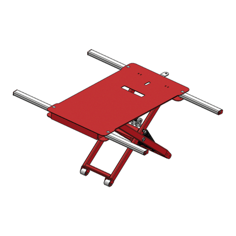
Astra miniLIFT&move User manual

User Manual
miniLIFT&move
Spray booths ·Welding ·Benches ·Lifts
CODE DESCRIPTION SERIAL NUMBER
AE100L miniLIFT&move


1 Information about this manual
1.1 Symbols of the manual
2 Intended use
3 Installation
3.1 Unpacking
3.2 Assembly
3.3 Start-up
3.4 First use
4 Operation
4.1 Installation of the pads
4.2 Positioning of the elevator
4.3 Positioning of basic pads
4.4 Lift maneuver (front side of the vehicle)
4.5 Lift maneuver (rear side of the vehicle)
4.6 Installation of the safety stands
4.7 Installation and use of the sliding pads
4.8 Installation of the 4x4 adapters
5 Maintenance
5.1 Maintenance plan
5.2 Cleaning
5.3 Periodical inspection
6 Technical description
6.1 Technical data
6.2 Schematic pneumatic circuit
6.3 Exploded view
6.4 CE Declaration of Conformity
8 Inspection log
Page. 04
Page. 04
Page. 04
Page. 05
Page. 05
Page. 06
Page. 07
Page. 07
Page. 08
Page. 08
Page. 09
Page. 10
Page. 11
Page. 11
Page. 12
Page. 12
Page. 14
Page. 15
Page. 15
Page. 15
Page. 16
Page. 16
Page. 16
Page. 16
Page. 17
Page. 22
Page. 23
ÍNDICE
3USER MANUAL · AE100L MINILIFT&MOVE

For your safety, read this manual carefully before installing or using this product.
The “miniLIFT&move” is a scissor lift with two pneumatic actuators and small size designed for those wor-
kshops that that is able to lift half of the vehicle up to 2.200kg. This lift is able to carry out three different
movements:
· Front side elevation
· Rear side elevation
· Displacement of the vehicle
This means that however you lift the car, the front, the rear or the side wheels will be always on the ground.
1 Information about this manual
2 Intended use
1.1 Symbols of the manual
DANGER
CAUTION
NOTE
Possible risk of death, serious injury and / or material damage.
Possible risk of injury and / or material damage.
Recommendations for the correct use.
4USER MANUAL · AE100L MINILIFT&MOVE

1. Elevator
2. Handle
3. Wheels
4. Basic pads
5. Pad Supports
6. Sliding pads
7. Safety stands
8. Manual and pins
02
01
03 04 05 06 07 08
3 Installation
3.1 Unpacking
DANGER
Incorrect transportation. Always use the proper devices for this function: forklift, crane, etc).
Always wearing protective shoes.
All the parts that make up the elevator are sent in a simple pallet (“Figure 01”).
MANIPULATION OF THE CONTENT
figure 01
· Place the lift in horizontal position and fix the crane to the elevator with two belts at each end to transport
the structure correctly.
· Make sure that the tapes are in good condition and correctly placed.
· Place the lift in the area intended for use so that the wheels are in contact with the pavement.
5USER MANUAL · AE100L MINILIFT&MOVE

· Set the wheels as shown in the “Figure 02”
· Set the handle as shown in the “Figure 03”
figure 02
3.2 Assembly
figure 03
6
USER MANUAL · AE100L MINILIFT&MOVE

01
02
03
· Set the pneumatic quick connector (Not supplied) as shown in the “Figure 04”.
3.3 Start up
3.4 First use
· Connect the compressed air funnel and check the air pressure (from 6 to 9 BAR).
· Check that there are no leaks in the pneumatic ducts, the actuating valve and / or the pneumatic actua-
tors.
· Press the button “01” from the pneumatic valve as shown in the “Figure 05”.
· Press the button “02” from the pneumatic valve as shown in the “Figure 05”.
CHECKING THE LIFT / DESCENT MANEUVER
CHECKING THE VACUUM MANEUVER
figure 04
figure 05 figure 06
· Raise the lift until the proper height in order to set the sliding pads (look on the 4.7 section).
· Press and hold the actuators 01 and 03 of the valve to start the vacuum maneuver (“Figure 05”).
7USER MANUAL · AE100L MINILIFT&MOVE

4 How it works
4.1 Installation of the pads
· In order to use the basic pads in the lift, we must set before the adaptors (“Figure 07”).
· Fix the basic pads in the adaptors as shown in the “Figure 08”.
In those vehicles where there are no “heel pads”, but you can find some other lifting points under the
chassis, you can use the following optional pads (not included in the basic package).
· If you got these optional pads, you should follow the “Figure 09” in order to use them properly.
figure 07
figure 08
figure 09
8USER MANUAL · AE100L MINILIFT&MOVE

4.2 Positioning of the elevator
· The handle is articulated to avoid tripping on the perimeter of the car. It is recommended to fold it and
secure it with the pin as shown in the “Figure 12”.
· Drive the lift by means of the handle and position it under the vehicle according to the desired part to be
lifted (“Figure 10”). See section 4.4 and 4.5 (Lift / lower maneuver).
· Follow the steps specified in the “Figure 11” for place the handle in horizontal position.
DANGER
Always use the lift in areas with no obstructions neither inclinations.
CAUTION
The elevator must remain perpendicular to the length of the car (“Figure 12”).
If the vehicle is new or it’s wet, you must clean the area where the pads work, in order to
prevent any possible slide.
figure 12
figure 10 figure 11
9
USER MANUAL · AE100L MINILIFT&MOVE

MÍN
123mm
MÁX
215mm
4.3 Positioning of the basic pads
Place the basic pad behind the area of the lifting point (in the middle) as shown in the “Figure 13”.
DANGER
Place the basic supports at the same length from the platform and without exceeding the
maximum as shown in the “Figure 14”.
figure 13
figure 14
10
USER MANUAL · AE100L MINILIFT&MOVE

01
UP
02
DOWN
Gravity center
01
UP
02
DOWN
Gravity center
4.4 Lift maneuver (front side of the vehicle)
4.5 Lift maneuver (rear side of the vehicle)
PELIGRO
PELIGRO
Never place the lift in the gravity point of the car.
Place the supplied safety stands once the vehicle has been raised.
Never place the lift in the gravity point of the car.
Place the supplied safety stands once the vehicle has been raised.
figura 15 figura 16
figura 17 figura 16
Place the lift next to the gravity point of the car, in the front/rear part of the vehicle, as it’s showed on the
“Figure 15” and press the relevant button (“Figure 16”).
Place the lift next to the gravity point of the car, in the front/rear part of the vehicle, as it’s shown in the
“Figure 17” and press the relevant button (“Figure 16”).
11USER MANUAL · AE100L MINILIFT&MOVE

4.7 Installation and use of the sliding pads
4.6 Installation of the safety stands
Place the safety stands as shown in the “Figure 18”, and descend the lift until the stands make contact
with the ground.
Place the sliding pads under the axle as shown in the “Figure 19”.
DANGER
DANGER
Safety stands do not allow the operator to work under the vehicle.
Never use the wheels when the 4x4 & SUV adaptors are being used.
figure 18
figure 19
12
USER MANUAL · AE100L MINILIFT&MOVE

01
02
Block the sliding pads using the lock as shown in the “Figure 20”.
Descend the lift until the wheels of the sliding pads make contact with the ground and, afterwards, do the
vacuum as shown in the “Figure 21 and 06” in order to have the lift only supported by the wheels.
After that, the lift is ready to be moved by pushing the vehicle (“Figure 22”).
figure 20
figure 21 figure 06
figure 22
13
USER MANUAL · AE100L MINILIFT&MOVE

4.8 Installation of the 4x4 adaptors
Place the 4x4 adaptors as shown in the “Figure 23”, being able to combine the basic pads or the optional
pads (not supplied with the basic package).
DANGER
Do not use sliding pads under any circumstances when the 4x4 adapters are installed.
figure 24
figure 23
DANGER
Place the basic supports at the same length from the platform and without exceeding the
maximum as shown in the “Figure 24”.
14USER MANUAL · AE100L MINILIFT&MOVE

figure 26 figure 27figure 25
5.1 Maintenance plan
Before each use.
At 6 months.
At 12 months.
At 6 years.
· Check the operation of the controls.
· Visual inspection of damages and leaks.
· Cleaning (see point 5.2).
· Periodic inspection (see point 5.7).
TYPE TASKSPERIOD
5.2 Cleaning
Remove the dirt with a wet cloth and dry it later with another cloth.
Follow the indications in “Figure 25,26 and 27” for the correct use of the 4x4 adaptors.
CAUTION
Do not use abrasive detergents or water jet directly on the lift.
5 Maintenance
· Replacing the pneumatic ducts.
· Replacing the pneumatic actuators.
15USER MANUAL · AE100L MINILIFT&MOVE

5.7 Periodical inspection
6.2 Schematic Pneumatic Circuit
The lift must be inspected by a specialist at least once every 12 months.
Here are the inspection points:
Mechanic system
Pneumatic system
· Review of all the points of union between scissors (seeger and bolts).
· Tighten all existing nuts.
· Check the welds for cracks or deformations.
· Check the readability of the adhesives.
· Review of all pneumatic ducts in search of leaks, cracks, deformations or any deterioration
symbol.
NOTE
We recommend that you keep an exhaustive control of elevator inspections in the “inspec-
tion log” that can be found on page 20 of the manual.
6.1 Technical data
Maximum load admitted
Maximum height from the ground
Minimum height from the ground
Maximum width
Minimum length
Long maximum
Weight of the structure with accessories
Pneumatic circuit pressure
Ascent time
Descent time
2200 Kg
550 mm
123 mm
634 mm
1630 mm
2180 mm
160 Kg
6 a 8 BAR
13 seconds
17 seconds
6 Technical description
figure 28
16USER MANUAL · AE100L MINILIFT&MOVE

6.3 Exploded view
figure 29
17USER MANUAL · AE100L MINILIFT&MOVE

figure 30
01
04
05
13
14
06
07
08
09
10
11
12
02
03
15
16
17
18
19
20
21
22
23
24
25
18USER MANUAL · AE100L MINILIFT&MOVE

figure 31
26
27
28
29
30
31
32
33
34
35
36
37
38
39
40
41
42
43
42
41
44
19USER MANUAL · AE100L MINILIFT&MOVE

45
46
47
48
49
50
51
52
53
54
55
56
57
54
58
01
59
60
61
62
52
47
63
64
65
figure 32
20
USER MANUAL · AE100L MINILIFT&MOVE
Table of contents
Other Astra Lifting System manuals
Popular Lifting System manuals by other brands

REHOBOT
REHOBOT HTJ1200 instructions

BlueSky Mast
BlueSky Mast AL2 STANDARD Series Quick reference sheet

Harmar Mobility
Harmar Mobility PARAGON OUTLANDER FULL Owner's manual & warranty information

Mortuary Lift
Mortuary Lift Ultimate 1000 Lift ML-013P Operation & maintenance manual

Manitou
Manitou 150 AETJ C Operator's manual

Vestil
Vestil FPG Series manual

Ergoswiss
Ergoswiss SLA 13 Series Operating instruction

Pittsburgh Automotive
Pittsburgh Automotive 60659 Owner's manual & safety instructions

Lifeline
Lifeline EAGLE owner's guide

Vestil
Vestil CH-200 Series instruction manual

Atlas
Atlas PV-10PX Installation & operation manual

AMGO
AMGO PRO-12 Installation and service manual