Pro Pack Solutions EAGLE T210 User manual

©Copyright 2012
EAGLE T210
Contents
1. Machine Safety Information 1
2. Machine Installation and Debug 5
3. Machine Operation 9
5. Maintenance and Troubleshooting 12
6. Main Parts, Illustrations and Parts Lists 14
Distributed by:
Pro Pack Solutions, Inc.
P.O. Box 327
Loganville, Georgia 30052
Ph 770-554-1187
www.ProPackSolutions.com

©Copyright 2012
1
1. Machine Safety Information
1.1 Specifications
Specifications
Item EAGLE T210
Power Supply 110V, 60Hz
Carton Size L(6” - ∞) x W(7” – 19.68”) x H(4.7” – 18.9”)
(Fig 1-1)
Max Load 75 lbs
Tape Width 2-3”
Tape Length 1000-2000 yds
Sealing Speed ~30 cartons/minute
Machine Dimensions 38.2” x 35” x 50.3”
Shipping Weight 529 lbs
1.1.1 Sealing Specification of Carton (Fig 1-1)
Fig 1-1
The box range is as follows:
Length is 6” - unlimited
Width is 7” – 19.68”
Height is 4.7” – 18.9”
H
L
W

©Copyright 2012
2
1.1.2 Dimensions of Tape Head (Fig 1-2)
L=16.7”
W=4.25”
H=18.89”
Fig 1-2
1.1.3 The Tab Length (Fig 1-3)
Fig 1-3
Dimension “A” in Fig 1-3 is the adjustable tab length with a range of 2-3”.
1.1.4 Adjusting the Tape Length (Fig 1-4)
Fig 1-4
Move the guiding tape wheel from hole 1 to hole 6 to shorten the tape length.
w
H
L
A
A

©Copyright 2012
3
1.2 Safety Caution Symbol
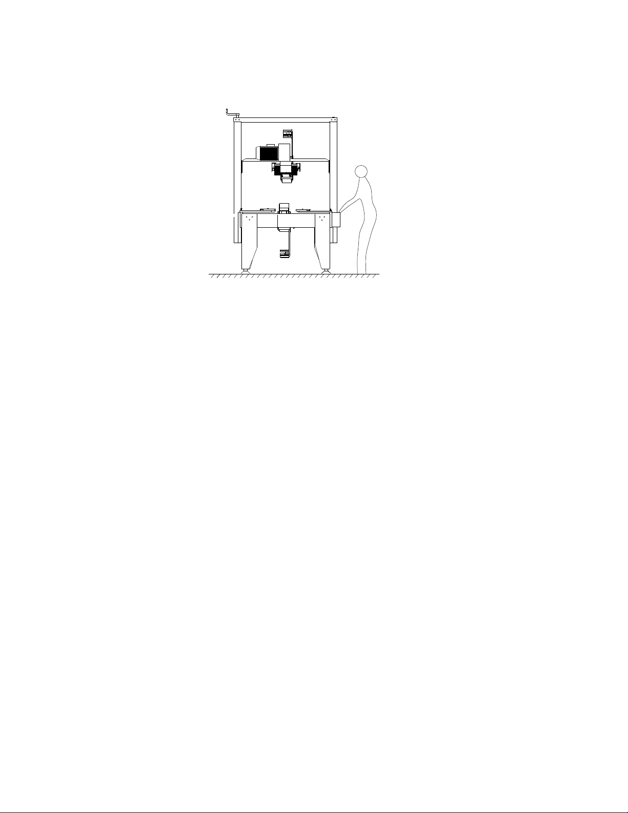
Safety Caution Symbol locations shown in Fig 1-5:
Fig 1-5
Notice: The sign of shows the belt is rotating, keep hands away.
The sign of shows there is motor and electric box, operate the
machine carefully.
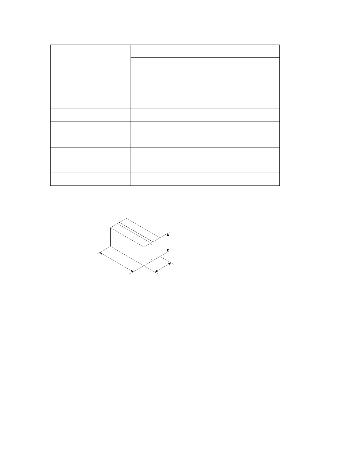
1.3 Outline and Application Field
This is an automatic case sealing machine using pressure-sensitive tape such as
PVC and BOPP. It can be set to conform to the shape of the carton and seal boxes
for packaging. This machine has a wide range of applications including the
following fields: chemical fiber field, tobacco leaf drying, pharmaceutical,
publication, refrigeration and air-conditioning, household appliances, ceramics,
etc.
ELECTRIC SHOCK
operate carefully
DANGER
CUT
keep hands away
DANGER
ROLLING
keep hands away
DANGER
DANGER
operate carefully
ELECTRIC SHOCK
DANGER
keep hands away
ROLLING
ROLLING
keep hands away
DANGER
ROLLING
keep hands away
DANGER
DANGER
keep hands away
CUT

©Copyright 2012
4
1.4 Position of Operation (Fig 1-6)
While operating the machine, the employee should stand a minimum of 4” away
from the front of the machine.
Fig 1-6
1.5 Safety Precautions to Operate Machine
1. Verify the power supply for the machine. This machine uses 110V, 60Hz,
single phase power.
2. To avoid cutting fingers, do not touch the blade on the tape head.
3. Do not flush the machine with water.
4. Do not force through or remove cartons while the machine is in operation.
5. Do not put hands on the side conveyors.
1.6 Hearing Safety
1.6.1 Noise: ≤75DB

©Copyright 2012
5
2Machine Installation and Debug
2.1 Installation, Transportation and Storage
2.1.1 Machine Structure and Components Illustration (Fig 2-1)
1. Upright Post Assembly
2. Tape Head Carriage
3. Top Box Squeezer
4. Bottom Conveyor System
5. Electric Box
6. Base Frame
7. Side Guide Rails
8. Tape Head
9. Height Adjustment Handle
Fig 2-1
2.1.2 Installation
Install Upright Post Assembly
(Fig 2-2) Attach upright post assembly to the base frame with screws provided.
(Fig 2-3)
Fig 2-2
Fig 2-3

©Copyright 2012
6
Install Tape Head Carriage
Attach the tape head carriage to the upright post assembly with screws provided.
(Fig 2-4)
Fig 2-4
Install Tape Head
Rest the upper tape head on the carriage placing the notches in the rear of the tape
head onto the supporting shaft. (Fig 2-5) Pull out the draw rod by the key ring,
lower the tape head and release the key ring. For the lower tape head, remove the
front supporting shaft. Rest the rear of the tape head on the rear supporting shaft.
Place the front supporting shaft on the angled notches in the front of the tape head
and lower the tape head down, guiding the pin into the notches in the frame.
(Fig2-6)
Supporting Axle
Fig 2-5
Fig 2-6

©Copyright 2012
7
Install Table Extensions
Align the holes in the extension with the posts in the frame and carefully lower the
table extension. (Fig 2-7)
Screw Hole
Fig 2-7
2.1.3 Transportation
Transport by lift truck (Fig 2-8)
Fig 2-8
2.1.4 Operation environment conditions
It should be far from smoke, dry and ventilated. Humidity≤98%
Normal environment temperature should be within 32-104° F.
No special requirements for electromagnetic radiation.
2.2 Debug
2.2.1 Check Prior to Operation
1. Make sure all nuts and bolts are properly fastened.
2. Make sure the motor and electrical equipment are dry and well insulated.

©Copyright 2012
8
3. Make sure the external power is correct for the power supply of the machine.
2.2.2 Empty Operation
1. Turn on power; after 2-5 minutes verify the machine is operating normally.
2. Rotate the width adjustment handle by hand to assure that the movement of the
side conveyor system is easy.
3. Rotate the height adjustment handle by hand to assure that the movement of
the tape carriage is easy.
4. Make sure the belt is properly positioned.
5. Adjust the tightness of the belt.
6. Check that the tape is properly loaded on the tape head and that the action is
smooth when dispensing tape.

©Copyright 2012
9
3 Machine Operation
3.1 Functions of Control Panel (Fig 3-1)
1. Power Indicator
2. Start Button
3. Emergency Stop Button
Fig 3-1
3.2 Feeding the Adhesive Tape (Fig 3-2)
Fig 3-2
3.3 Operation Steps
1. Plug in the machine, turn Power Switch to the on position, twist emergency stop
button to the right until it pops up if it was depressed.
2. Press start button, manually push the case through, the belt will drive it and seal
automatically.
3.4 Daily Maintenance
Proper maintenance to the case sealer prolongs the life of the machine and helps to
avoid problems that would affect the machines production efficiency.
3.4.1 Lubrication
The sealing speed of this machine is very fast. Therefore the machine parts should
be lubricated often.
3
2
1
ADHESIVE
Emergency stop
button

©Copyright 2012
10
3.5 Adjustable Position
3.5.1 Adjusting the Height of the Workbench (Fig 4-4)
Put the nut plate in the leg support according to the figure. Then loosely connect
the fastening piece and the nut plate with the socket head cap screws. Insert the
leg between the leg support and nut plate. The leg can now be adjusted up and
down as desired. Tighten the screws.
Fig 3-3
3.5.2 Adjusting the Height of the Carriage (Fig 3-4)
Rotate the height adjustment handle by hand to adjust the carriage height. Rotate
the handle clockwise to move the carriage up and counter clockwise to move the
carriage down.
Fig 3-4

©Copyright 2012
11
3.5.3 Adjusting the Width of the Top Box Squeezer
Loosen the knobs and move each top box squeezer in the direction of the arrows 1
and 2, keeping the rollers close to the case tighten the knobs.
Hand Wheel
Fig 3-5

©Copyright 2012
12
4 Maintenance and Troubleshooting
4.1 Safety Warning on Maintenance
1. Be sure to turn off main power supply
4.2 Regular Maintenance and Cleaning
1. Regularly check for loose screws
2. Lubricate moving parts of the machine on a regular basis
3. Clean the surface of the machine
4. On a daily basis clean off the blades
5. If the machine will not be used for a long period of time, the blade should be
oiled to protect it.
4.3 Troubleshooting
1. If the tape is not centered on the box; adjust to position of the tape. (Fig 4-1)
Fig 4-1
2. If the tape does not cut off; the blade is too high and is scraping the box or the
blade is too low and not able to cut through the tape. (Fig 4-2)
3. If the tape does not stick to the box; the quality of tape is not good or the front
wheel has seized. (Fig 4-2)
Fig 4-2

©Copyright 2012
13
4.4 Items Repaired or Changed by Operator
No. Name Part #
1 Belt 1520MM
2 Chain 06B
3 Wheel FJG-3A-413
4.5 Items Repaired or Changed by Maintenance Staff
No. Name Part #
1 Drive wheel FJG-3A-419

©Copyright 2012
14
5 Main Parts, Illustrations and Parts List
1 Machine Frame Component
No. Name Part # Qty Remark
1 Machine Frame FJG-1D-206 1
2 Front Leg Support FJG-1A-110 2
3 Nut Plate FJG-1A-112 4
4 Leg FJG-1A-113 4
5 Rear Leg Support FJG-1A-111 1 ea L & R

©Copyright 2012
15
2Upright post component
No. Name Part # Qty Remark
1 Handle FJG-1A-193 1
2 Hub FJG-1A-944 1
3 Handle Mount FJG-1A-917 1
4 Beam FJG-1A-176 1
5 Chain 1 06B
6 Height Adjustment
Gear FJG-1A-179 2
7 Lift Screw Bearing 6905-2Z 2
8 Upper Supporting
Board FJ-3AS-21 2
9 Lift Screw (L) FJ-3AS-26 1
10 Upright Post Body FJ-3AS-24 2
11 Lift Screw (R) FJ-3AS-25 1
12 Lift Body FJ-3AS-19 2
13 Idler Wheel FJ-1B-11 4
14 Nut FJ-3AS-20 2

©Copyright 2012
16
3 Tape Head Carriage (Upper Belt Drive)
No. Name Part # Qty Remark
1 Bracket FJG-1A-141 2
2 Belt Guard FJ-2A-135 2
3 Conveyor Belt 1520mm 2
4 Shaft FJ-3A-415 12
5 Drive Wheel FJ-3A-419 2
6 Motor Support FJ-2A-126 1
7 Motor Cover FJ-3A-437 1
8 Transmission Axle FJ-2A-124 1
9 Motor CV200-20ZG3
1
10 Drive Wheel FJ-3A-416 12
11 Wheel FJ-3A-413 2
12 Tensioning Axle FJ-2A-123 1
13 Retaining Plate FJ-1A-703 1
14 Brush Support FJ-1A-701 1
13
14
8
10
4
65
3
2
1
12
16
19
9
17
18 2021
11
15
7

©Copyright 2012
17
15 Support Bars FJG-1A-131.2
2
16 Supporting Axle FJ-1-440 1
17 Shaft FJ-3A-807 1
18 Spring Holder FJ-3A-808 1
19 Fixed Block FJG-1A-127 1
20 Compression Spring FJ-1A-930 1
21 Sliding Block FJ-3A-806 1
22 Motor Sprocket FJ-2A-132.1 1 Z-16
23 Chain 1 06B
24 Bearing Bracket FJ-1D-304 2
25 Lower Sprocket FJ-2A-132 1 Z-13
26 Switch Stop FJ-3A-450 1

©Copyright 2012
18
4 Top Box Squeezer
No. Name Part # Qty Remark
1 Knob FJG-1A-197 1
2 Locking Frame FJG-1A-194 1
3 Backing Guard FJG-1A-943 1
4 Frame FJG-1A-116 1
5 Bolt 2
6 Gasket 2
7 Squeezer Bearing 6203-2Z 2
8 Contact Roller FJG-1A-142 2
9 Round Nut 2

©Copyright 2012
19
5 Rolling Component
No. Name Part # Qty Remark
1 Supporting Ring FJG-1A-201 2
Long Shaft FJG-1A-180 1
2 Short Shaft FJG-1A-181 1
Long Roller FJG-1A-182 1
3 Short Roller FJG-1A-183 1
1
3
2
Table of contents
Popular Industrial Equipment manuals by other brands

Graco
Graco 918478 Instructions-parts list

Dando
Dando TERRIER Mk 1 Operating and maintenance manual

Afag
Afag BF20 Operating & installation instructions

HEADQUARTERS
HEADQUARTERS DD-5111V Technical manual

Buhnen
Buhnen HB 11 Translation of the original operating instructions

schmersal
schmersal AZM300Z-I2-ST-1P2P-A Instructions for operation

Command access
Command access MLP-UL-M KIT Insert Instructions

Advantech
Advantech PWS 472 Startup manual

RealWear
RealWear HMT-1 installation instructions

EZG
EZG Grout Hog UGH75 owner's manual

Plockmatic
Plockmatic HCI3500 Installation instruction

Taco Electronic Solutions
Taco Electronic Solutions iWorx MPU2 Application guide